Claas Arion 420-410 (A32) Tractors Operator Manual EN
$50.00
- Brand: Claas
- Model: Arion 420-410 (A32) Tractors
- Type Of Manual: Operator Manual
- Language: EN
- Format: PDF(s)
- Size: 380 MB
File List:
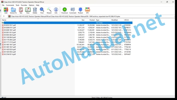
00 0018 552 1.pdf
00 0288 614 1.pdf
00 0289 108 1.pdf
00 0301 051 0.pdf
00 0303 482 0.pdf
00 1169 984 0.pdf
00 1170 296 2.pdf
00 1171 315 0.pdf
00 1405 164 7.pdf
00 1405 184 7.pdf
00 1420 028 4.pdf
00 1420 056 2.pdf
00 2194 931 4.pdf
00 0018 552 1.pdf:
TELEMATICS Website
Table of contents
1 About this Concise Operator’s Manual
1.1 Notes on the manual
1.1.1 Validity of manual
1.1.2 Notes regarding the Concise Operator’s Manual
1.1.3 Notes on warranty
2 Safety
2.1 Intended use
2.1.1 Proper use
3 Product description
3.1 Overview and method of operation
3.1.1 TELEMATICS product variants
3.1.2 TONI (TELEMATICS on implements)
3.1.3 Fleet View
3.1.4 TELEMATICS basic
3.1.5 TELEMATICS advanced
3.1.6 TELEMATICS professional
3.1.7 TELEMATICS app
4 Operating and control elements
4.1 TELEMATICS overview
4.1.1 Illustration conventions of buttons and navigation elements
4.1.2 Symbols and colours
4.2 Menu structure
4.2.1 Start screen
4.2.2 TELEMATICS website site map
4.2.3 Main menu overview
4.2.4
4.2.5
4.2.6
00 0289 108 1.pdf:
CTIC 2800 2.0CTIC 2.0
Table of contents
1 Introduction
1.1 General information
1.1.1 Validity of manual
1.1.2 Information about this Operator’s Manual
1.1.3 Symbols and notes
1.1.4 Optional equipment
1.1.5 Maintenance information
1.1.6 Warranty information
1.1.7 Qualified specialist workshop
1.1.8 Spare parts and technical questions
1.2 Intended use
1.2.1 Intended use
1.2.2 Reasonably foreseeable misuse
2 Safety
2.1 Identifying warnings
2.1.1 Hazard signs
2.1.2 Signal word
2.2 Safety rules
2.2.1 Importance of Operator’s Manual
2.2.2 Optional equipment and spare parts
2.2.3 Danger due to damage to the tyre pressure control system
2.2.4 Technical condition
2.2.5 Complying with technical limit values
2.2.6 Keeping protective devices functional
2.2.7 Personal protective equipment
2.2.8 Dangers when driving on the road and on the field
2.2.9 Environmental protection and disposal
2.2.10 Noise can damage your health
2.2.11 Pressurised fluids
2.2.12 Compressed air
2.2.13 Hot surfaces
2.2.14 Maintenance work and repair work
2.2.15 Welding work prohibited
3 Product description
3.1 Package list
3.1.1 Delivery state
3.2 Overview and method of operation
3.2.1 Tyre pressure control system
3.2.2 Tyre pressure control system
3.3 Safety devices
3.3.1 Mechanical and electronic safety features
Pressure limitation
System behaviour when an air line is torn off
Manual operation
3.4 Identification plates and identification numbers
3.4.1 Identification plate of tyre pressure control system
4 Operating and display elements
4.1 Monitor
4.1.1 Overview of operating screen
4.2
4.2.1
4.2.2
4.3
4.3.1
4.3.2
4.3.3
4.3.4
4.4
4.4.1
5 Technical specifications
5.1 Tyre pressure control system
5.1.1 Properties
5.1.2 Lubricants
6 Handling
6.1 Transport and storage
6.1.1 Transport
Compressor
6.1.2 Storage
7 Preparing the product
7.1 Putting into operation
7.1.1 Carry out prior to operation
Installing the tyre pressure control system
Workplace description
8 Operation
8.1 Tyre pressure control system
8.1.1 Observe prior to operating the system
8.1.2 Parking position
Removing the rotary transmission leadthrough cover
Removing the rotary transmission leadthrough cover
Moving the hose packages of front wheels to the parking position
Moving the hose package of the rear right wheel to the parking position
Moving the hose package of the rear left wheel to the parking position
Installing the cover on the rotary transmission leadthrough
Installing the cover on the rotary transmission leadthrough
Removing the rotary transmission leadthroughs
8.1.3 Parking position
Removing the rotary transmission leadthrough cover
Removing the rotary transmission leadthrough cover
Moving the hose packages of front wheels to the parking position
Moving the hose package of the rear right wheel to the parking position
Moving the hose package of the rear left wheel to the parking position
Installing the cover on the rotary transmission leadthrough
Installing the cover on the rotary transmission leadthrough
Removing the rotary transmission leadthroughs
8.1.4 Working position
Installing the rotary couplings
Moving the hose packages of front wheels to the working position
Moving the hose package of the rear right wheel to the working position
Moving the hose package of the rear left wheel to the working position
Installing the cover on the rotary transmission leadthrough
Installing the cover on the rotary transmission leadthrough
8.1.5 Working position
Installing the rotary couplings
Moving the hose packages of front wheels to the working position
Moving the hose package of the rear right wheel to the working position
Moving the hose package of the rear left wheel to the working position
Installing the cover on the rotary transmission leadthrough
Installing the cover on the rotary transmission leadthrough
8.1.6 Determining the wheel loads
Fundamentals for determining wheel loads
Determining the wheel load on the front axle
Determining the wheel load on the rear axle
Determining the wheel load of the hitched implement
Example of how to calculate the wheel loads
8.1.7 Activating the tyre pressure control system
8.1.8 Deactivating the tyre pressure control system
8.1.9 Creating a profile
Entering the profile name
Setting the tyre pressure values for the towing vehicle
Enabling the trailer
Trailer priority circuit
Setting the tyre pressure values for the trailer
Selecting the tyre size
8.1.10 Changing the profile
8.1.11 Deleting the profile
8.1.12 Activating the profile
Operating the profile in
Changing set values in
Operating the profile in
9 Faults and remedies
9.1 Tyre pressure control system
9.1.1 Overview of possible problems with the tyre pressure control system
10 Maintenance
10.1 Maintenance interval overview
10.1.1 Operating hours
10.1.2 Every 10 operating hours or daily
10.1.3 Every 600 operating hours
10.1.4 Every 1200 operating hours or annually
10.1.5 Maintenance work every 2400 operating hours
10.2 Tyre pressure control system
10.2.1 Cleaning and preserving the tyre pressure control system
10.2.2 Checking and cleaning the compressor air filter
Checking the air filter
Cleaning the air filter
10.2.3 Changing the air filter element
10.2.4 Cap
Removing
Installing
10.2.5 Checking the compressor oil level
10.2.6 Checking the compressor oil level
10.2.7 Changing the compressor oil and oil filter
Changing the oil filter
Topping up oil
10.2.8 Replacing the compressor oil separator
11 Putting out of operation and disposal
11.1 General information
11.1.1 Putting out of operation and disposal
00 0301 051 0.pdf:
PROFI CAM 3
Table of contents
1 Introduction
1.1 Notes on the manual
1.1.1 Validity of manual
1.1.2 Information about this Operator’s Manual
1.1.3 Symbols and notes
1.1.4 Optional equipment
1.1.5 Qualified specialist workshop
1.1.6 Maintenance information
1.1.7 Warranty notes
1.1.8 Spare parts and technical questions
1.2 Intended use
1.2.1 Intended use
1.2.2 Reasonably foreseeable misuse
2 Safety
2.1 Identifying warnings
2.1.1 Hazard signs
2.1.2 Signal word
2.2 Safety rules
2.2.1 Meaning of Operator’s Manual
2.2.2 Observing safety decals and warnings
2.2.3 Optional equipment and spare parts
3 Product description
3.1 Overview and method of operation
3.1.1 How the PROFI CAM works
3.2 Identification plates and identification number
3.2.1 Position of identification plates
3.2.2 Explanation of PROFI CAM identification plate
3.3 Information on the product
3.3.1 CE marking
4 Operating and control elements
4.1 Camera system
4.1.1 Camera system monitor
4.2 Menu structure
4.2.1 Main menu
4.2.2
4.2.3 menu
4.2.4
4.2.5
4.2.6
5 Technical specifications
5.1 PROFI CAM
5.1.1 Monitor
5.1.2 Camera
5.1.3 Switch box
5.1.4 Degree of protection against foreign bodies and water
6 Preparing the product
6.1 Shutting down and securing the machine
6.1.1 Switching off and securing the machine
6.2 Prior to operation
6.2.1 Carry out prior to operation
6.2.2 Installing the sun protection
6.2.3 Aligning the camera
6.2.4 Connecting the camera electrics
7 Operation
7.1 Monitor
7.1.1 Switching on the monitor
7.1.2 Calling up the menu
7.1.3 Setting a menu item
7.1.4 Setting the image orientation
7.1.5 Setting automatic screen darkening
7.1.6 Image mirroring
7.1.7 Setting the trigger view
7.1.8 Setting the follow-up time for trigger view
7.1.9 Setting the display mode
7.1.10 Activating/deactivating a display mode
8 Faults and remedies
8.1 Electrical and electronic system
8.1.1 Overview of problems on PROFI CAM camera system
8.1.2 Replacing the switch box fuse
9 Maintenance
9.1 Maintenance intervals
9.1.1 Every 10 operating hours or daily
9.2 Camera system
9.2.1 Checking the camera system for dirt
9.2.2 Cleaning the camera
9.2.3 Cleaning the switch box
9.2.4 Cleaning the monitor
10 Placing out of operation and disposal
10.1 General Information
10.1.1 Putting out of operation and disposal
11 Technical terms and abbreviations
11.1 Abbreviations
11.1.1 Units
11.1.2 Abbreviations
11.1.3 Technical terms
00 0303 482 0.pdf:
PROFI CAM 4
Table of contents
1 Introduction
1.1 Notes on the manual
1.1.1 Validity of manual
1.1.2 Information about this Operator’s Manual
1.1.3 Symbols and notes
1.1.4 Optional equipment
1.1.5 Qualified specialist workshop
1.1.6 Maintenance information
1.1.7 Notes on warranty
1.1.8 Spare parts and technical questions
1.2 Intended use
1.2.1 Intended use
1.2.2 Reasonably foreseeable misuse
2 Safety
2.1 Identifying warnings
2.1.1 Hazard signs
2.1.2 Signal word
2.2 Safety rules
2.2.1 Meaning of Operator’s Manual
2.2.2 Structural changes
2.2.3 Optional equipment and spare parts
2.2.4 Operation only following proper putting into operation
2.2.5 Technical status
2.2.6 Respecting technical limit values
Respecting technical limit values
2.2.7 Hazards when driving on roads and fields
3 Product description
3.1 Overview and method of operation
3.1.1 How the PROFI CAM works
3.2 Identification plates and identification number
3.2.1 Identification plates
3.3 Information on the product
3.3.1 CE marking
4 Operating and display elements
4.1 Camera system
4.1.1 Camera system monitor
4.1.2 CEBIS
4.2 Menu structure
4.2.1 Main menu
4.2.2
4.2.3 menu
4.2.4
4.2.5
4.2.6
5 Technical specifications
5.1 PROFI CAM
5.1.1 Monitor
5.1.2 Camera
5.1.3 Switch box
6 Preparing the product
6.1 Switching off and securing the machine
6.1.1 Switching off and securing the machine
6.2 Prior to putting into operation
6.2.1 Carry out prior to operation
6.2.2 Installing the sun protection
6.2.3 Aligning the camera
7 Operation
7.1 Monitor
7.1.1 Switching on the monitor
7.1.2 Calling up the menu
7.1.3 Setting a menu item
7.1.4 Setting the image orientation
7.1.5 Setting automatic screen darkening
7.1.6 Image mirroring
7.1.7 Setting the trigger view
7.1.8 Setting the follow-up time for trigger view
7.1.9 Setting the display mode
7.1.10 Activating/deactivating a display mode
8 Faults and remedies
8.1 Electric and electronic system
8.1.1 Overview of problems on PROFI CAM camera system
9 Maintenance
9.1 Maintenance intervals
9.1.1 Every 10 operating hours or daily
9.2 Camera system
9.2.1 Checking the camera system for dirt
9.2.2 Cleaning the camera
9.2.3 Cleaning the switch box
9.2.4 Cleaning the monitor
10 Putting out of operation and disposal
10.1 General information
10.1.1 Putting out of operation and disposal
11 Technical terms and abbreviations
11.1 Abbreviations
11.1.1 Units
11.1.2 Abbreviations
11.1.3 Technical terms
00 1169 984 0.pdf:
Sensor case for tractors Stage IIIB, IV and VSensor case for tractors Stage IIIB, IV and VSensor case for Stage IIIB, IV and V tractors
Contents
1 Sensorkoffer – Sensor case – Sensor suitcase – Stage IIIB, IV & V
1.1 Auflistung Kofferinhalt
1.1 Listing case content
1.1 Presentation of the contents of the suitcase
00 1170 296 2.pdf:
AXION 900-800ARION 600-500-400
Table of contents
1 Introduction
1.1 Notes on the manual
1.1.1 Manual validity
2 Tractor preparation
2.1 Assembly parts and machine body
2.1.1 Legal equipment in accordance with regulation (EU) 167/2013
Tractors over 4.6 m in length: AXION 900, AXION 800, ARION 600 and ARION 500
Tractor with an overall width exceeding 2.55 m: AXION 900, AXION 800, ARION 600 and ARION 500
CIS tractor with an overall width exceeding 2.82 m and CEBIS tractor with an overall width exceeding 2.75 m: AXION 900, AXION 800, ARION 600 and 500
Tractor with an overall width exceeding 2.55 m: ARION 400
Tractor with an overall width of less than 2.55 m: ARION 600, 500 and 400
CIS tractor with an overall width of less than 2.82 m: AXION 900, AXION 800, ARION 600 and 500
CEBIS tractor with an overall width of less than 2.75 m: AXION 900, AXION 800, ARION 600 and 500
Deploy the signal strips
00 1171 315 0.pdf:
AXION 900-800 CEBISARION 600-500 CEBIS
Table of contents
1 Introduction
1.1 Notes on the manual
1.1.1 Manual validity
2 Operating and display elements
2.1 CEBIS
2.1.1 Work phases
Road mode
Field mode
ISO Terminal mode
2.1.2 Work phases
ISO Terminal mode
2.1.3
2.1.4
00 1405 164 7.pdf:
GPS PILOT
Table of contents
1 Introduction
1.1 General information
1.1.1 Validity of Manual
1.1.2 Information about this Operator’s Manual
1.1.3 Symbols and notes
1.1.4 Optional equipment
1.1.5 Qualified specialist workshop
1.1.6 Maintenance notes
1.1.7 Notes on warranty
1.1.8 Spare parts and technical questions
1.1.9 Licensing for road traffic
Sample report
Clearance certificate
General operating permit
1.2 Intended use
1.2.1 Intended use
1.2.2 Reasonably foreseeable misuse
2 Safety
2.1 Identifying warnings
2.1.1 Hazard signs
2.1.2 Signal word
2.2 Safety rules
2.2.1 Meaning of Operator’s Manual
2.2.2 Update of terminal software
2.2.3 Requirements made on all persons working with the product
2.2.4 Hazard areas
Hazard areas
2.2.5 Interaction between the control terminal and the machine or tractor
2.2.6 Structural changes
2.2.7 Optional equipment and spare parts
2.2.8 Use of USB devices
2.2.9 Operation only following proper putting into operation
2.2.10 Technical status
2.2.11 Hazard from damage on the product
2.2.12 Respecting technical limit values
Respecting technical limit values
2.2.13 Preparing the product for road travel
2.2.14 Hazards when driving on the road with an ISOBUS implement
Switching on the terminal during road travel.
2.2.15 Hazards when driving on the road and on the field
2.2.16 Electrocution by electrical system
2.2.17 Potentially fatal electric shock from overhead lines
2.2.18 Liquids under pressure
2.2.19 Maintenance operations and repair work
2.2.20 Driving with the GPS PILOT
Road travel
Fieldwork
2.2.21 Working with Task Control* and Section Control*
3 Product description
3.1 Overview and method of operation
3.1.1 Overview of GPS PILOT – Hydraulic system
3.1.2 Overview of GPS PILOT – Steer ready
3.1.3 Overview of GPS PILOT FLEX
3.1.4 Overview of GPS PILOT ex works
3.1.5 Overview of the S10 terminal
3.1.6 Overview of navigation computer (ECU)
3.1.7 Electric steering wheel
3.1.8 Overview of correction signals
EGNOS/WAAS/MSAS
Omnistar HP / XP / G2
RTK FIELD BASE and BASELINE HD
RTK FARM BASE
3.1.9 Module overview
BASELINE HD
RTK FIELD BASE
RTK (Motorola)
RTK FARM BASE
3.2 Safety devices
3.2.1 Automatic cut-out when the maximum speed is exceeded
3.2.2 Automatic cut-out when the speed falls below the minimum
3.2.3 Seat contact switch
3.2.4 Manual override
Electric steering wheel
3.3 Optional equipment
3.3.1 GPS L2*
3.3.2 GLONASS*
3.3.3 TURN IN*
3.3.4 AUTO TURN*
3.3.5 Task Control*
Task Control Basic*
Task Control Geo*
3.3.6 Section Control*
3.4 Identification plates and identification numbers
3.4.1 GPS PILOT identification plate
3.4.2 Identification plate of terminal
3.4.3 Identification plate of navigation controller
4 Operating and display elements
4.1 GPS PILOT
4.1.1 Master switch and drive switch
4.2 Overview of the S10 terminal
4.2.1 Layout conventions of buttons and displays
4.3 GPS PILOT menu structure
4.3.1 Start menu
Start menu without Task Control*
Start menu with Task Control*
4.3.2 Menu overview
4.3.3 Overview of display field
4.3.4
4.3.5
4.3.6
calibration step
6.3.30 Carrying out the
Creating an A=B line
Driving along an A=B line
6.3.31 Carrying out the
Creating an A=B line
Test run 1
Test run 2
Completing
6.3.32 Saving the vehicle profile
6.4 Initial operation of implement
6.4.1 Creating an implement profile check list
6.4.2 Creating an implement
Selecting the hitching type
Making implement settings
Making rate control settings
6.4.3 Coupling the ISOBUS implement
Automatic adoption of settings
Automatic update of implement geometry
6.4.4 Setting the implement settings
6.4.5 Setting the implement width
6.4.6 Setting the implement geometry
Front or rear implement offset
Trailed and actively trailed hitching types
Rear rigid and front rigid hitching types
Adjusting the left or right implement offset
Setting the overlap or the gap
Saving or rejecting entries
6.4.7 Setting the main boom
6.4.8 Setting the work step
6.4.9 Setting the Section View / Section Control* control type
6.4.10 Setting the rate control
Setting the control type
Setting the preview time
Setting the set value unit
6.4.11 Calibrating the turning radius
Perform calibration
Left turning circle
Right turning circle
Acknowledging the turning circle
6.5 Partial width display and partial width control settings
6.5.1 Setting the partial widths check list
6.5.2 Calling up the implement settings
6.5.3 Setting the number of partial widths
6.5.4 Setting the width of partial widths
6.5.5 Combining partial widths into groups
Setting the number
Combining into groups automatically
Editing the group
6.5.6 Setting the permitted overlap
6.5.7 Setting the reaction time
Setting the activation delay
Setting the deactivation delay
6.6 Initial setup of correction signal
6.6.1 First initialisation of GNSS signal
6.6.2 E-DIF
6.6.3 EGNOS/WAAS/MSAS
6.6.4 Omnistar HP / XP / G2
Settings on the terminal
6.6.5 RTK FIELD BASE and BASELINE HD
Setting the radio frequency
Adjusting the radio channel spacing
Saving or rejecting the settings
6.6.6 RTK (Motorola)
Selecting the
Selecting the reference station
6.6.7 RTK FARM BASE
Selecting the
Enabling RTK FARM BASE
6.6.8 RTK NET
TSM settings on the terminal
Setting the RTK NET login
Setting the SIM card settings
TSM settings by the CDS
6.6.9 RTK ready
6.7 Discontinuing subscriptions
6.7.1 Setting subscriptions
7 Operation
7.1 Checklists
7.1.1 Preparing field use
7.1.2 Using the GPS PILOT in fieldwork
7.1.3 Carrying out fieldwork GPS PILOT with Task Control*
7.1.4 Preparing road travel
7.2 S10 Terminal
7.2.1 Switching on the terminal
Start screen
7.2.2 Operating the entry elements
Keyboard
Number pad
Controller
Buttons with a stored list
7.2.3 Filtering lists
7.2.4 Switching off the terminal
7.2.5 Connecting a USB data memory to the terminal
7.3 GPS PILOT
7.3.1 Changing the GPS PILOT over to
7.3.2 Changing the GPS PILOT over to
7.3.3 Switching off the GPS PILOT
7.3.4 GPS status
7.3.5 GPS PILOT activation options
Activating GPS PILOT with the multifunction handle
Particularities
7.3.6 GPS PILOT deactivation options
Further switching-off conditions
Seat contact switch
Speed range
GPS signal
7.3.7 Folding the RTK radio antenna
Folding and engaging the RTK radio antenna
Folding and screwing down the RTK radio antenna
7.3.8 Retracting and extending the GNSS antenna.
7.4 System settings
7.4.1 Adjusting the brightness
7.4.2 Setting the language
7.4.3 Setting the units
7.4.4 Setting the time
7.4.5 Switching the worked area signal on or off
7.4.6 Setting the night-time mode
7.4.7 Setting the projection
7.4.8 Setting pre-engage
7.4.9 Setting smoothing
7.4.10 Setting the front fitting position mode
7.5 GPS settings
7.5.1 Displaying the GPS status
7.5.2 Switching the BEIDOU signal on or off
7.5.3 Setting the NMEA 0183 output
Use of GNSS signal by other units
7.5.4 Setting E-DIF
Setting a reference point
Updating the reference point
7.5.5 Setting SBAS / EGNOS
7.5.6 Calling up the L band status
7.5.7 Setting the L band settings
7.5.8 Setting the RTK FIELD BASE and BASELINE HD settings
7.5.9 Making RTK settings
7.5.10 Selecting RTK FARM BASE
Selecting RTK FARM BASE manually
Switching automatic selection on or off
7.5.11 Deleting RTK FARM BASE
7.5.12 Setting RTK NET settings
Switching the automatic RTK NET connection on or off
Establishing or terminating a connection manually
7.6 Map settings
7.6.1 Adjusting the A=B lines display
7.6.2 Adjusting the A=B grid spacing
7.6.3 Adjusting pre-set markers
7.6.4 Automatic recording of the coverage map
7.7 Vehicle settings
7.7.1 Changing over the direction of travel indicator
7.7.2 Setting the sensitivity and the aggressiveness
Setting the sensitivity
Setting the aggressiveness
7.7.3 Loading the vehicle profile
7.7.4 Editing the vehicle profile
7.7.5 Importing the vehicle profile
7.7.6 Exporting the vehicle profile
7.7.7 Deleting the vehicle profile
7.8 Implement settings
7.8.1 Selecting the implement profile
7.8.2 Editing an implement profile
7.8.3 Importing the implement profile
7.8.4 Exporting the implement profile
7.8.5 Deleting the implement profile
7.9 Driver’s profiles
7.9.1 Creating a new driver’s profile
Naming the driver
Entering the address
Entering the driver contact information
Saving or rejecting the driver’s profile
7.9.2 Editing the driver’s profile
7.9.3 Selects the driver’s profile
7.9.4 Importing a driver’s profile
7.9.5 Exporting a driver’s profile
7.9.6 Deleting the driver’s profile
7.10 Product profiles
7.10.1 Creating product profiles
Naming the product
Selecting the product type
Selecting the carrier substance
Selecting the state of aggregation
Selecting the mixture
Selecting the filler
Saving the product
7.10.2 Editing product profiles
7.11 Task Management
7.11.1 Creating a new job
Selecting a customer
Selecting a farm
Selecting a field
Selecting the crop type
Selecting a driver
Entering the temperature
Entering the air humidity
Entering the wind speed
Entering the wind direction
Starting a job
7.11.2 Continuing a job
7.11.3 Editing a job
7.11.4 Renaming a job
7.11.5 Selecting a job
7.11.6 Creating a template
7.11.7 Using templates
7.11.8 Importing a job
7.11.9 Exporting a job
7.11.10 Deleting an article
7.11.11 Finishing a job
7.12 ISOBUS work record management
7.12.1 ISOBUS task management functions
7.12.2 ISOBUS task management settings
Setting the Task Control version
Setting the function instance
7.12.3 Creating a new task
Creating a new task via the start menu
Creating a new task via the
Entering the task name
Selecting a field
Selecting a work step
Adjusting the product mixture
Selecting the product mixture
Selecting an implement
Claas Operator Manual PDF
Claas Operator Manual PDF
Claas RANGER 975-964, 970, 960 und PLUS (516) Telehandlers Operator Manual DE
Claas Operator Manual PDF
Claas QUANTUM 3800 K 3500 P-K-S (613) Loader Wagons Operator Manual DE

 Claas ROLLANT 254 RC (754) Baler Operator Manual DE