Claas Tucano 560 (L06) Combines Operator Manual EN
$50.00
- Brand: Claas
- Model: Tucano 560 (L06) Combines
- Type Of Manual: Operator Manual
- Language: EN
- Format: PDF(s)
- Size: 375 MB
File List:
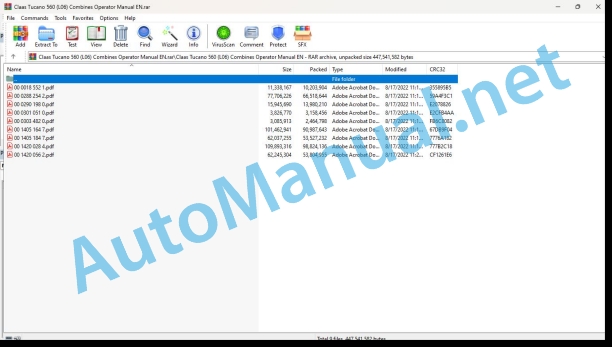
00 0018 552 1.pdf
00 0288 254 2.pdf
00 0290 198 0.pdf
00 0301 051 0.pdf
00 0303 482 0.pdf
00 1405 164 7.pdf
00 1405 184 7.pdf
00 1420 028 4.pdf
00 1420 056 2.pdf
00 0018 552 1.pdf:
TELEMATICS Website
Table of contents
1 About this Concise Operator’s Manual
1.1 Notes on the manual
1.1.1 Validity of manual
1.1.2 Notes regarding the Concise Operator’s Manual
1.1.3 Notes on warranty
2.1 Intended use
2.1.1 Proper use
3 Product description
3.1 Overview and method of operation
3.1.1 TELEMATICS product variants
3.1.2 TONI (TELEMATICS on implements)
3.1.3 Fleet View
3.1.4 TELEMATICS basic
3.1.5 TELEMATICS advanced
3.1.6 TELEMATICS professional
3.1.7 TELEMATICS app
4 Operating and control elements
4.1 TELEMATICS overview
4.1.1 Illustration conventions of buttons and navigation elements
4.1.2 Symbols and colours
4.2 Menu structure
4.2.1 Start screen
4.2.2 TELEMATICS website site map
4.2.3 Main menu overview
4.2.4
4.2.5
4.2.6
00 0290 198 0.pdf:
1 Einleitung
1.1 Allgemeine Hinweise
1.1.1 Handhabung der Anleitung
Texte und Abbildungen
Richtungsangaben
1.1.2 Gültigkeit der Anleitung
2 Sicherheit
2.1 Beachten
2.1.1 Besonders zu beachten
2.1.2 Kennzeichnung von Warn- und Gefahrenhinweisen
3 Lieferumfang
3.1 Raupenlaufwerk
3.1.1 Nachrüstsatz
4.1 Allgemeine Hinweise
4.1.1 Allgemeine Warnhinweise Umbau
4.2 Lenkachsenerhöhung für Raupenlaufwerk TUCANO 450 / 440
4.2.1 Lieferumfang kontrollieren
4.2.2 Lenkachsenerhöhung anbauen
4.3 Installation for Raupenlaufwerk TUCANO 450 / 440
4.3.1 Lieferumfang kontrollieren
4.3.2 Unterbau anbauen
4.4 Laufwerke für Raupenlaufwerk TUCANO 450 / 440
4.4.1 Lieferumfang kontrollieren
4.4.2 Laufwerke anbauen
4.5 Ketten für Raupenlaufwerk TUCANO 450 / 440
4.5.1 Lieferumfang lieren
4.5.2 Ketten anbauen
4.6 Aufstiegsleiter für Raupenlaufwerk TUCANO 450 / 440
4.6.1 Lieferumfang kontrollieren
4.6.2 Wishing Leiter anbauen
4.6.3 Probelauf vorbereiten und durchführen
5 Einstellung Arbeitseinsatz
5.1 Allgemeine Hinweise
5.1.1 Allgemeine Warnhinweise Einstellungen Arbeitseinsatz
5.2 Fahrwerk TUCANO 450 / 440
5.2.1 Raupenlaufwerke abbauen
5.3 Fahrwerk TUCANO 450 / 440
5.3.1 Raupenlaufwerke anbauen
6 Schmierplan Raupenlaufwerk
6.1 Schmierstellen
6.1.1 Schmierstoffe
6.1.2 Schmier interval
6.1.3 Schmierstellen – 10 h
1 Introduction
1.1 General Information
1.1.1 How to use this manual
Texts and figures
Directions
1.1.2 Validity of manual
2.1 Important
2.1.1 Important information
2.1.2 Identification of warning and danger signs
3 Package list
3.1 Track roller unit
3.1.1 Supplementary kit
4 Conversion
4.1 General Information
4.1.1 General warnings for conversion
4.2 Rear axle height increase for trk roller unit TUCANO 450 / 440
4.2.1 Checking the shipping package
4.2.2 Fitting the rear axle height increase
4.3 Substructure for track roller unit TUCANO 450 / 440
4.3.1 Checking the shipping package
4.3.2 Fitting the substructure
4.4 Traveling gears for track roller unit TUCANO 450 / 440
4.4.1 Checking the shipping package
4.4.2 Installing the traveling gears
4.5 Tracks for track roller unit TUCANO 450 / 440
4.5.1 Checking the shipping package
4.5.2 Fitting the tracks
4.6 Ladder for track roller unit TUCANO 450 / 440
4.6.1 Checking the shipping package
4.6.2 Installing the front ladder
4.6.3 Prepare and carry out a test run
5 Fieldwork settings
5.1 General Information
5.1.1 General warnings for fieldwork settings
5.2 Chassis of TUCANO 450 / 440
5.2.1 Removing the track roller units
5.3 Chassis of TUCANO 450 / 440
5.3.1 Fitting track roller units
6 Lubrication chart of track roller unit
6.1 Lubrication points
6.1.1 Lubricants
6.1.2 Greasing cycles
6.1.3 Lubrication points – 10 h
1 Introduction
1.1 General indications
1.1.1 Using the instructions
Texts and images
Directional indications
1.1.2 Validity of the manual
2 Safety Medications
2.1 Observe
2.1.1 Especially important
2.1.2 Reporting of warnings and warnings
3 Suminister Council
3.1 Orugas running train
3.1.1 Rear assembly work
4 Transformation
4.1 General indications
4.1.1 General information on Transformation advice
4.2 Elevating the direct drive for the TUCANO 450 / 440 wheel train
4.2.1 Check the chief executive officer
4.2.2 Mount the elevation of the steering wheel
4.3 Lower structure for the TUCANO 450 / 440 running gear
4.3.1 Check the chief executive officer
4.3.2 Assemble the lower structure
4.4 Running trains for the TUCANO 450 / 440 running train
4.4.1 Check the chief executive officer
4.4.2 Mount the running gear
4.5 Chains for the TUCANO 450 / 440 wheel train
4.5.1 Check the chief executive officer
4.5.2 Assemble the cadenas
4.6 Access ladder for the TUCANO 450 / 440 running gear
4.6.1 Check the chief executive officer
4.6.2 Assemble the ladder
4.6.3 Prepare and carry out an operational test
5 Adjustment in operational service
5.1 General indications
5.1.1 General warning indications Adjustments for working use
5.2 Chasis TUCANO 450 / 440
5.2.1 Disassemble the trains of rodaje de orugas
5.3 Chasis TUCANO 450 / 440
5.3.1 Mount the wheel trains
6 Diagram for engraving the train of wheels of wheels
6.1 Entry points
6.1.1 Lubricants
6.1.2 Engaging intervals
6.1.3 Engaging points – 10 h
1. Introduction
1.1 General indications
1.1.1 Application of the user manual
Texts and figures
Direction data
1.1.2 Validity of the user manual
2.1 To be observed
2.1.1 Important warnings
2.1.2 Warning and danger signs
3 Total supply
3.1 Track carriage
3.1.1 Upgrade kit
4.1 General indications
4.1.1 General warnings for modification
4.2 Raising the steering axle for the TUCANO 450 / 440 track carriage
4.2.1 Check the delivery assembly
4.2.2 Fitting the steering axle riser
4.3 Lower structure for the TUCANO 450 / 440 track carriage
4.3.1 Check the delivery assembly
4.3.2 Assembly of the lower structure
4.4 Trolleys for TUCANO 450 / 440 tracks
4.4.1 Check the delivery assembly
4.4.2 Assembling the trolleys
4.5 Chains for the TUCANO 450 / 440 track carriage
4.5.1 Check the delivery assembly
4.5.2 Assembly of catenaries
4.6 Ladder for the TUCANO 450 / 440 track trolley
4.6.1 Check the delivery assembly
4.6.2 Assembling the front ladder
4.6.3 Preparation and execution of operational tests
5 Adjustment for practical use in the field
5.1 General indications
5.1.1 General warnings for use in the field
5.2 TUCANO 450 / 440 axle
5.2.1 Disassembly of the track carriage
5.3 TUCANO 450 / 440 axle
5.3.1 Assembling the track carriage
6 Track carriage lubrication diagram
6.1 Greasing points
6.1.1 Lubricants
6.1.2 Lubrication intervals
6.1.3 Lubrication points – 10 h
1 Ââåäåíèå
1.1 Îáùèå óêàçàíèØ
1.1.1 Èñïîëüçîâàíèå ²óêîâîäñòâà
Òåêñòû è èçîá²àæåíèØ
ÓêàçàíèØ íàï²àâëåíèØ
1.1.2 Äåéñòâèå ²óêîâîäñòâà
2 Áåçîïàñíîñòü
2.1.1 Îá²àòèòü îñîáîå âíèìàíèå
2.1.2 Îáîçíà÷åíèå ï²åäóï²åæäåíèé è óêàçàíèé îá îïàñíîñòØõ
3 Îáúåì ïîñòàâêè
3.1 Ãóñåíè÷íûé äâèæèòåëü
3.1.1 Êîìïëåêò äëØ äîîáî²óäîâàíèØ
4 Ïå²åîáî²óäîâàíèå
4.1 Îáùèå óêàçàíèØ
4.1.1 Îáùèå ï²åäóï²åæäà ùèå óêàçàíèØ ïî ïå²åîáî²óäîâàíè
4.2 Óâåëè÷åíèå âûñîòû óï²àâëØåìîãî ìîñòà äëØ ãóñåíè÷íîãî äâèæèòåëØ TUCANO 450 / 440
4????????
4.5 ???? ??? ??????????? ????????? TUCANO 450 / 440
4.5.1 ϲ?????? ????? ????????
4.5.2 ????????? ?????????? ?????
4.6 ???????? ??? ??????????? ????????? TUCANO 450 / 440
4.6.1 ϲ?????? ????? ????????
4.6.2 ?????????? ????? ????????
4.6.3 ?????????? is ?????????? ??????? ?????
5 ???????? ??? ??????
5.1 ????? ????????
5.1.1 ????? ????????? ??? ???????? ???????? ??? ????????????
5.2 ??????? ???????? TUCANO 450 / 440
5.2.1 ????? ?????????? ?????????
5.3 ??????? ???????? TUCANO 450 / 440
5.3.1 ?????????? ?????????? ?????????
6 ???? ?????? ??????????? ?????????
6.1 ????? ??????
6.1.1 ????????? ????????
6.1.2 ???????? ??????
6.1.3 ????? ?????? – 10 ?????
00 0301 051 0.pdf:
PROFI CAM 3
Table of contents
1 Introduction
1.1 Notes on the manual
1.1.1 Validity of manual
1.1.2 Information about this Operator’s Manual
1.1.3 Symbols and notes
1.1.4 Optional equipment
1.1.5 Qualified specialist workshop
1.1.6 Maintenance information
1.1.7 Warranty notes
1.1.8 Spare parts and technical questions
1.2 Intended use
1.2.1 Intended use
1.2.2 Reasonably foreseeable misuse
2.1 Identifying warnings
2.1.1 Hazard signs
2.1.2 Signal word
2.2 Safety rules
2.2.1 Meaning of Operator’s Manual
2.2.2 Observing safety decals and warnings
2.2.3 Optional equipment and spare parts
3 Product description
3.1 Overview and method of operation
3.1.1 How the PROFI CAM works
3.2 Identification plates and identification number
3.2.1 Position of identification plates
3.2.2 Explanation of PROFI CAM identification plate
3.3 Information on the product
3.3.1 CE marking
4 Operating and control elements
4.1 Camera system
4.1.1 Camera system monitor
4.2 Menu structure
4.2.1 Main menu
4.2.2
4.2.3 menu
4.2.4
4.2.5
4.2.6
5 Technical specifications
5.1 PROFI CAM
5.1.1 Monitor
5.1.2 Camera
5.1.3 Switch box
5.1.4 Degree of protection against foreign bodies and water
6 Preparing the product
6.1 Shutting down and securing the machine
6.1.1 Switching off and securing the machine
6.2 Prior to operation
6.2.1 Carry out prior to operation
6.2.2 Installing the sun protection
6.2.3 Aligning the camera
6.2.4 Connecting the camera electrics
7 Operation
7.1 Monitor
7.1.1 Switching on the monitor
7.1.2 Calling up the menu
7.1.3 Setting a menu item
7.1.4 Setting the image orientation
7.1.5 Setting automatic screen darkening
7.1.6 Image mirroring
7.1.7 Setting the trigger view
7.1.8 Setting the follow-up time for trigger view
7.1.9 Setting the display mode
7.1.10 Activating/deactivating a display mode
8 Faults and remedies
8.1 Electrical and electronic system
8.1.1 Overview of problems on PROFI CAM camera system
8.1.2 Replacing the switch box fuse
9 Maintenance
9.1 Maintenance intervals
9.1.1 Every 10 operating hours or daily
9.2 Camera system
9.2.1 Checking the camera system for dirt
9.2.2 Cleaning the camera
9.2.3 Cleaning the switch box
9.2.4 Cleaning the monitor
10 Placing out of operation and disposal
10.1 General Information
10.1.1 Putting out of operation and disposal
11 Technical terms and abbreviations
11.1 Abbreviations
11.1.1 Units
11.1.2 Abbreviations
11.1.3 Technical terms
00 0303 482 0.pdf:
PROFI CAM 4
Table of contents
1 Introduction
1.1 Notes on the manual
1.1.1 Validity of manual
1.1.2 Information about this Operator’s Manual
1.1.3 Symbols and notes
1.1.4 Optional equipment
1.1.5 Qualified specialist workshop
1.1.6 Maintenance information
1.1.7 Notes on warranty
1.1.8 Spare parts and technical questions
1.2 Intended use
1.2.1 Intended use
1.2.2 Reasonably foreseeable misuse
2.1 Identifying warnings
2.1.1 Hazard signs
2.1.2 Signal word
2.2 Safety rules
2.2.1 Meaning of Operator’s Manual
2.2.2 Structural changes
2.2.3 Optional equipment and spare parts
2.2.4 Operation only following proper putting into operation
2.2.5 Technical status
2.2.6 Respecting technical limit values
Respecting technical limit values
2.2.7 Hazards when driving on roads and fields
3 Product description
3.1 Overview and method of operation
3.1.1 How the PROFI CAM works
3.2 Identification plates and identification number
3.2.1 Identification plates
3.3 Information on the product
3.3.1 CE marking
4 Operating and display elements
4.1 Camera system
4.1.1 Camera system monitor
4.1.2 CEBIS
4.2 Menu structure
4.2.1 Main menu
4.2.2
4.2.3 menu
4.2.4
4.2.5
4.2.6
5 Technical specifications
5.1 PROFI CAM
5.1.1 Monitor
5.1.2 Camera
5.1.3 Switch box
6 Preparing the product
6.1 Switching off and securing the machine
6.1.1 Switching off and securing the machine
6.2 Prior to putting into operation
6.2.1 Carry out prior to operation
6.2.2 Installing the sun protection
6.2.3 Aligning the camera
7 Operation
7.1 Monitor
7.1.1 Switching on the monitor
7.1.2 Calling up the menu
7.1.3 Setting a menu item
7.1.4 Setting the image orientation
7.1.5 Setting automatic screen darkening
7.1.6 Image mirroring
7.1.7 Setting the trigger view
7.1.8 Setting the follow-up time for trigger view
7.1.9 Setting the display mode
7.1.10 Activating/deactivating a display mode
8 Faults and remedies
8.1 Electric and electronic system
8.1.1 Overview of problems on PROFI CAM camera system
9 Maintenance
9.1 Maintenance intervals
9.1.1 Every 10 operating hours or daily
9.2 Camera system
9.2.1 Checking the camera system for dirt
9.2.2 Cleaning the camera
9.2.3 Cleaning the switch box
9.2.4 Cleaning the monitor
10 Putting out of operation and disposal
10.1 General information
10.1.1 Putting out of operation and disposal
11 Technical terms and abbreviations
11.1 Abbreviations
11.1.1 Units
11.1.2 Abbreviations
11.1.3 Technical terms
00 1405 164 7.pdf:
Table of contents
1 Introduction
1.1 General information
1.1.1 Validity of Manual
1.1.2 Information about this Operator’s Manual
1.1.3 Symbols and notes
1.1.4 Optional equipment
1.1.5 Qualified specialist workshop
1.1.6 Maintenance notes
1.1.7 Notes on warranty
1.1.8 Spare parts and technical questions
1.1.9 Licensing for road traffic
Sample report
Clearance certificate
General operating permit
1.2 Intended use
1.2.1 Intended use
1.2.2 Reasonably foreseeable misuse
2.1 Identifying warnings
2.1.1 Hazard signs
2.1.2 Signal word
2.2 Safety rules
2.2.1 Meaning of Operator’s Manual
2.2.2 Update of terminal software
2.2.3 Requirements made on all persons working with the product
2.2.4 Hazard areas
Hazard areas
2.2.5 Interaction between the control terminal and the machine or tractor
2.2.6 Structural changes
2.2.7 Optional equipment and spare parts
2.2.8 Use of USB devices
2.2.9 Operation only following proper putting into operation
2.2.10 Technical status
2.2.11 Hazard from damage on the product
2.2.12 Respecting technical limit values
Respecting technical limit values
2.2.13 Preparing the product for road travel
2.2.14 Hazards when driving on the road with an ISOBUS implement
Switching on the terminal during road travel.
2.2.15 Hazards when driving on the road and on the field
2.2.16 Electrocution by electrical system
2.2.17 Potentially fatal electric shock from overhead lines
2.2.18 Liquids under pressure
2.2.19 Maintenance operations and repair work
2.2.20 Driving with the GPS PILOT
Road travel
2.2.21 Working with Task Control* and Section Control*
3 Product description
3.1 Overview and method of operation
3.1.1 Overview of GPS PILOT – Hydraulic system
3.1.2 Overview of GPS PILOT – Steer ready
3.1.3 Overview of GPS PILOT FLEX
3.1.4 Overview of GPS PILOT ex works
3.1.5 Overview of the S10 terminal
3.1.6 Overview of navigation computer (ECU)
3.1.7 Electric steering wheel
3.1.8 Overview of correction signals
EGNOS/WAAS/MSAS
Omnistar HP / XP / G2
RTK FIELD BASE and BASELINE HD
RTK FARM BASE
3.1.9 Module overview
BASELINE HD
RTK FIELD BASE
RTK (Motorola)
RTK FARM BASE
3.2 Safety devices
3.2.1 Automatic cut-out when the maximum speed is exceeded
3.2.2 Automatic cut-out when the speed falls below the minimum
3.2.3 Seat contact switch
3.2.4 Manual override
Electric steering wheel
3.3 Optional equipment
3.3.1 GPS L2*
3.3.2 GLONASS*
3.3.3 TURN IN*
3.3.4 AUTO TURN*
3.3.5 Task Control*
Task Control Basic*
Task Control Geo*
3.3.6 Section Control*
3.4 Identification plates and identification numbers
3.4.1 GPS PILOT identification plate
3.4.2 Identification plate of terminal
3.4.3 Identification plate of navigation controller
4 Operating and display elements
4.1 GPS PILOT
4.1.1 Master switch and drive switch
4.2 Overview of the S10 terminal
4.2.1 Layout conventions of buttons and displays
4.3 GPS PILOT menu structure
4.3.1 Start menu
Start menu without Task Control*
Start menu with Task Control*
4.3.2 Menu overview
4.3.3 Overview of display field
4.3.4
4.3.5
4.3.6
calibration step
6.3.30 Carrying out the
Creating an A=B line
Driving along an A=B line
6.3.31 Carrying out the
Creating an A=B line
Test run 1
Test run 2
Completing
6.3.32 Saving the vehicle profile
6.4 Initial operation of implement
6.4.1 Creating an implement profile check list
6.4.2 Creating an implement
Selecting the hitching type
Making implement settings
Making rate control settings
6.4.3 Coupling the ISOBUS implement
Automatic adoption of settings
Automatic update of implement geometry
6.4.4 Setting the implement settings
6.4.5 Setting the implement width
6.4.6 Setting the implement geometry
Front or rear implement offset
Trailed and actively trailed hitching types
Rear rigid and front rigid hitching types
Adjusting the left or right implement offset
Setting the overlap or the gap
Saving or rejecting entries
6.4.7 Setting the main boom
6.4.8 Setting the work step
6.4.9 Setting the Section View / Section Control* control type
6.4.10 Setting the rate control
Setting the control type
Setting the preview time
Setting the set value unit
6.4.11 Calibrating the turning radius
Perform calibration
Left turning circle
Right turning circle
Acknowledging the turning circle
6.5 Partial width display and partial width control settings
6.5.1 Setting the partial widths check list
6.5.2 Calling up the implement settings
6.5.3 Setting the number of partial widths
6.5.4 Setting the width of partial widths
6.5.5 Combining partial widths into groups
Setting the number
Combining into groups automatically
Editing the group
6.5.6 Setting the permitted overlap
6.5.7 Setting the reaction time
Setting the activation delay
Setting the deactivation delay
6.6 Initial setup of correction signal
6.6.1 First initialisation of GNSS signal
6.6.2 E-DIF
6.6.3 EGNOS/WAAS/MSAS
6.6.4 Omnistar HP / XP / G2
Settings on the terminal
6.6.5 RTK FIELD BASE and BASELINE HD
Setting the radio frequency
Adjusting the radio channel spacing
Saving or rejecting the settings
6.6.6 RTK (Motorola)
Selecting the
Selecting the reference station
6.6.7 RTK FARM BASE
Selecting the
Enabling RTK FARM BASE
6.6.8 RTK NET
TSM settings on the terminal
Setting the RTK NET login
Setting the SIM card settings
TSM settings by the CDS
6.6.9 RTK ready
6.7 Discontinuing subscriptions
6.7.1 Setting subscriptions
7 Operation
7.1 Checklists
7.1.1 Preparing field use
7.1.2 Using the GPS PILOT in fieldwork
7.1.3 Carrying out fieldwork GPS PILOT with Task Control*
7.1.4 Preparing road travel
7.2 S10 Terminal
7.2.1 Switching on the terminal
Start screen
7.2.2 Operating the entry elements
Number pad
Controller
Buttons with a stored list
7.2.3 Filtering lists
7.2.4 Switching off the terminal
7.2.5 Connecting a USB data memory to the terminal
7.3 GPS PILOT
7.3.1 Changing the GPS PILOT over to
7.3.2 Changing the GPS PILOT over to
7.3.3 Switching off the GPS PILOT
7.3.4 GPS status
7.3.5 GPS PILOT activation options
Activating GPS PILOT with the multifunction handle
Particularities
7.3.6 GPS PILOT deactivation options
Further switching-off conditions
Seat contact switch
Speed range
GPS signal
7.3.7 Folding the RTK radio antenna
Folding and engaging the RTK radio antenna
Folding and screwing down the RTK radio antenna
7.3.8 Retracting and extending the GNSS antenna.
7.4 System settings
7.4.1 Adjusting the brightness
7.4.2 Setting the language
7.4.3 Setting the units
7.4.4 Setting the time
7.4.5 Switching the worked area signal on or off
7.4.6 Setting the night-time mode
7.4.7 Setting the projection
7.4.8 Setting pre-engage
7.4.9 Setting smoothing
7.4.10 Setting the front fitting position mode
7.5 GPS settings
7.5.1 Displaying the GPS status
7.5.2 Switching the BEIDOU signal on or off
7.5.3 Setting the NMEA 0183 output
Use of GNSS signal by other units
7.5.4 Setting E-DIF
Setting a reference point
Updating the reference point
7.5.5 Setting SBAS / EGNOS
7.5.6 Calling up the L band status
7.5.7 Setting the L band settings
7.5.8 Setting the RTK FIELD BASE and BASELINE HD settings
7.5.9 Making RTK settings
7.5.10 Selecting RTK FARM BASE
Selecting RTK FARM BASE manually
Switching automatic selection on or off
7.5.11 Deleting RTK FARM BASE
7.5.12 Setting RTK NET settings
Switching the automatic RTK NET connection on or off
Establishing or terminating a connection manually
7.6 Map settings
7.6.1 Adjusting the A=B lines display
7.6.2 Adjusting the A=B grid spacing
7.6.3 Adjusting pre-set markers
7.6.4 Automatic recording of the coverage map
7.7 Vehicle settings
7.7.1 Changing over the direction of travel indicator
7.7.2 Setting the sensitivity and the aggressiveness
Setting the sensitivity
Setting the aggressiveness
7.7.3 Loading the vehicle profile
7.7.4 Editing the vehicle profile
7.7.5 Importing the vehicle profile
7.7.6 Exporting the vehicle profile
7.7.7 Deleting the vehicle profile
7.8 Implement settings
7.8.1 Selecting the implement profile
7.8.2 Editing an implement profile
7.8.3 Importing the implement profile
7.8.4 Exporting the implement profile
7.8.5 Deleting the implement profile
7.9 Driver’s profiles
7.9.1 Creating a new driver’s profile
Naming the driver
Entering the address
Entering the driver contact information
Saving or rejecting the driver’s profile
7.9.2 Editing the driver’s profile
7.9.3 Selects the driver’s profile
7.9.4 Importing a driver’s profile
7.9.5 Exporting a driver’s profile
7.9.6 Deleting the driver’s profile
7.10 Product profiles
7.10.1 Creating product profiles
Naming the product
Selecting the product type
Selecting the carrier substance
Selecting the state of aggregation
Selecting the mixture
Selecting the filler
Saving the product
7.10.2 Editing product profiles
7.11 Task Management
7.11.1 Creating a new job
Selecting a customer
Selecting a farm
Selecting a field
Selecting the crop type
Selecting a driver
Entering the temperature
Entering the air humidity
Entering the wind speed
Entering the wind direction
Starting a job
7.11.2 Continuing a job
7.11.3 Editing a job
7.11.4 Renaming a job
7.11.5 Selecting a job
7.11.6 Creating a template
7.11.7 Using templates
7.11.8 Importing a job
7.11.9 Exporting a job
7.11.10 Deleting an article
7.11.11 Finishing a job
7.12 ISOBUS work record management
7.12.1 ISOBUS task management functions
7.12.2 ISOBUS task management settings
Setting the Task Control version
Setting the function instance
7.12.3 Creating a new task
Creating a new task via the start menu
Creating a new task via the
Entering the task name
Selecting a field
Selecting a work step
Adjusting the product mixture
Selecting the product mixture
Selecting an implement
Entering the target rate
Entering the composition
Saving or rejecting
Selecting an implements
Entering a comment
Creating a task
7.12.4 Copying a task
7.12.5 Editing a task
7.12.6 Selecting a task
7.12.7 Starting and pausing a task
7.12.8 Finishing a task
7.12.9 Displaying task information
Calling up information for the current task
Calling up information for any task
Task information
Task details
7.12.10 Displaying the counter values in the map view
7.12.11 Printing counter values
Explanation of printout
7.12.12 Creating master data
Creating a customer
Creating a farm
Creating a field
Creating the crop type and variety
Creating a crop type
Creating a crop variety
Saving or rejecting
Creating a work step
Creating a pro
Claas Operator Manual PDF
Claas RANGER 975-964, 970, 960 und PLUS (516) Telehandlers Operator Manual DE
Claas Operator Manual PDF
Claas Operator Manual PDF
Claas Operator Manual PDF

 Claas ROLLANT 260 (765) Baler Operator Manual DE