Claas Conspeed 6 8-70 75 Fc Linear (H02) Combines Operator Manual EN
$50.00
- Model: Conspeed 6 8-70 75 Fc Linear (H02) Combines
- Type Of Manual: Operator Manual
- Language: EN
- Format: PDF(s)
- Size: 27.5 MB
File List:
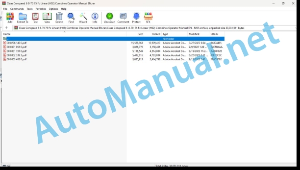
00 0296 149 0.pdf
00 0301 051 0.pdf
00 0301 731 0.pdf
00 0302 339 3.pdf
00 0303 482 0.pdf
00 0296 149 0.pdf:
CONSPEED 8-75 FC – 4-70 C LINEAR
Table of contents
1 To this Operator’s Manual
1.1 Notes on the manual
1.1.1 General instructions
1.1.2 Validity of manual
1.1.3 Handling of manual
1.1.4 Symbols and notes
1.1.5 Machine equipment
1.1.6 Specifications
2 Safety
2.1 Safety instructions in this manual
2.1.1 Marking of warning and hazard notes
2.2 Safety instructions for use
2.2.1 Observe when working on the machine
2.2.2 Of special importance
2.2.3 General safety and accident prevention regulations
2.2.4 Sensibly foreseeable misuse
2.2.5 Intended use
2.2.6 Precautionary measures
2.2.7 Road travel
2.2.8 Applying the feed rake conveyor safety lock
2.2.9 Moving out the feed rake conveyor safety lock
2.2.10 Compressed air and water
2.2.11 Danger of injury from hydraulic liquid
2.2.12 Burn prevention
2.2.13 Oils
2.2.14 Fire prevention and explosion prevention
2.2.15 Lines, tubes and hoses
2.2.16 Before every start-up
2.2.17 First aid measures
2.2.18 Loading and lashing down the front attachment
2.3 Safety decals on the machine
2.3.1 Safety decals
2.3.2 Position of safety decals
3 Machine description
3.1 Overview and method of operation
3.1.1 Overview of CONSPEED LINEAR
3.1.2 Function of CONSPEED LINEAR
3.2 Identification plates and identification number
3.2.1 Position of identification plates
3.2.2 Explanation of machine identification plate
3.2.3 Spare parts and technical questions
3.3 Optional machine equipment
3.3.1 Intake auger speed sprocket
3.3.2 Main gearbox gear pairs
3.3.3 Chopper unit shear bar
3.3.4 Slide height increase
3.3.5 Cover raiser
3.3.6 Sunflower kit
3.3.7 Down maize auger
3.3.8 Stubble breaker
3.3.9 Slides
3.3.10 Ear catching rubber
3.3.11 Safety bar
3.3.12 AUTO CONTOUR touch sensor
3.3.13 AUTO PILOT
3.3.14 Transport trailer*
4 Technical specifications
4.1 CONSPEED LINEAR
4.1.1 Dimensions
4.1.2 Weights
4.1.3 Machine body
4.1.4 Lubricants
5 Machine preparation
5.1 Prior to operation
5.1.1 Carry out prior to initial commissioning
5.1.2 Carry out prior to every operation
5.2 Assembling the front attachment
5.2.1 Fitting the cover tip
5.2.2 Adjusting the gathering point transport position
5.2.3 Installing the stubble breakers*
5.2.4 Fitting the slides*
5.2.5 Installing the safety bar socket*
5.2.6 Installing the chopper unit* shear bar
5.2.7 Installing the ear catching rubber*
Bolt-on ear catching rubber*
Plug-in ear catching rubber*
5.3 Mounting front attachment
5.3.1 Installing the front attachment
5.3.2 Adapting the machine
5.3.3 Selecting the universal drive shaft
5.3.4 Converting universal drive shafts
Checking the universal drive shaft
Removing the universal drive shaft
Installing the universal drive shaft
5.3.5 Suspending the front attachment
5.3.6 Locking the front attachment
5.3.7 Mounting the multi-coupler
5.3.8 Installing the universal drive shaft
5.3.9 Retracting the jack stands
5.3.10 Checking the stripper profile
5.3.11 Learning the end stops of the hydraulic snapping plate adjustment
5.3.12 Identifying the hydraulic oil
5.4 Removing front attachment
5.4.1 Removing the front attachment
5.4.2 Removing the multi-coupler
5.4.3 Removing the universal drive shaft
5.4.4 Unlocking the front attachment
5.4.5 Extending the jack stands
5.4.6 Unhitching front attachment
5.5 Prepare road travel
5.5.1 Installing the safety bar*
5.5.2 Installing the safety bar
5.5.3 Installing safety guards
5.6 Prepare field work
5.6.1 Removing the safety bar
5.6.2 Removing the safety guards
5.7 Loading the machine
5.7.1 Loading and lashing down the front attachment
6 Operation
6.1 Driving on the road
6.1.1 Road travel
6.1.2 Folding to transport position
6.2 Fieldwork
6.2.1 Fieldwork
6.2.2 Folding to working position
6.3 Feeder unit
6.3.1 Adjusting the feed rate
6.3.2 Installing the intake auger sprocket with 74 teeth*
6.4 Snapping device
6.4.1 Adjusting the gathering point
Rough adjustment
Fine adjustment of middle gathering points
Fine adjustment of outside gathering points
6.4.2 Locking the cover
6.4.3 Setting the cover to the maintenance position
6.4.4 Adjusting the snapping plates mechanically
6.4.5 Adjusting the snapping plates hydraulically
7 Faults and remedies
7.1 Overview of faults
7.1.1 Problems and remedies – CONSPEED
8 Maintenance
8.1 Maintenance operations in general
8.1.1 Fixing material
8.2 Overview maintenance intervals
8.2.1 Handling of maintenance intervals
8.2.2 Before the harvest
8.2.3 After the first 10 operating hours
8.2.4 After the first 20 operating hours
8.2.5 After the first 50 operating hours
8.2.6 Every 10 operating hours
8.2.7 Every 50 operating hours
8.2.8 Every 100 operating hours
8.2.9 Every 150 operating hours
8.2.10 Every 250 operating hours
8.2.11 Every 500 operating hours or annually
8.2.12 After the harvest
8.3 Gearbox / Clutch / Universal drive shaft
8.3.1 Draining the main gearbox oil
8.3.2 Topping up main gearbox oil
8.3.3 Checking the main gearbox oil
8.3.4 Draining the main gearbox oil
8.3.5 Topping up main gearbox oil
8.3.6 Checking the main gearbox oil
8.3.7 Draining the picker gearbox oil
8.3.8 Topping up picker gearbox oil
8.3.9 Checking the picker gearbox oil
8.3.10 Checking the intake auger drive overload clutch
8.4 Drives
8.4.1 Adjusting the intake auger drive chain
8.5 Snapping device
8.5.1 Adjusting the stripper plates
8.5.2 Adjusting the snapping plates
8.5.3 Checking the snapping roller knives
8.5.4 Replacing snapping roller knives
8.5.5 Adjusting the feed rake chains
8.5.6 Cleaning the feed rake chain
8.6 Chopping
8.6.1 Changing the cutting cylinder knives
8.6.2 Checking the chopper knives
8.6.3 Checking the chopper knife tightening torque
8.7 Lubrication chart
8.7.1 Grease the grease points every 10 operating hours
8.7.2 Grease the grease points every 50 operating hours
8.7.3 Grease the grease points every 100 operating hours
Grease points – every 100 operating hours, rear
Grease points – every 100 operating hours, front
8.7.4 Grease the grease points every 250 operating hours
9 Placing out of operation and disposal
9.1 General Information
9.1.1 Putting out of operation and disposal
10 EC declaration of conformity
10.1 CONSPEED LINEAR
10.1.1 EC Declaration of Conformity
11 Technical terms and abbreviations
11.1 Terms and explanations
11.1.1 Technical terms
11.1.2 Abbreviations
00 0301 051 0.pdf:
PROFI CAM 3
Table of contents
1 Introduction
1.1 Notes on the manual
1.1.1 Validity of manual
1.1.2 Information about this Operator’s Manual
1.1.3 Symbols and notes
1.1.4 Optional equipment
1.1.5 Qualified specialist workshop
1.1.6 Maintenance information
1.1.7 Warranty notes
1.1.8 Spare parts and technical questions
1.2 Intended use
1.2.1 Intended use
1.2.2 Reasonably foreseeable misuse
2 Safety
2.1 Identifying warnings
2.1.1 Hazard signs
2.1.2 Signal word
2.2 Safety rules
2.2.1 Meaning of Operator’s Manual
2.2.2 Observing safety decals and warnings
2.2.3 Optional equipment and spare parts
3 Product description
3.1 Overview and method of operation
3.1.1 How the PROFI CAM works
3.2 Identification plates and identification number
3.2.1 Position of identification plates
3.2.2 Explanation of PROFI CAM identification plate
3.3 Information on the product
3.3.1 CE marking
4 Operating and control elements
4.1 Camera system
4.1.1 Camera system monitor
4.2 Menu structure
4.2.1 Main menu
4.2.2
4.2.3
4.2.4
4.2.5
4.2.6
5 Technical specifications
5.1 PROFI CAM
5.1.1 Monitor
5.1.2 Camera
5.1.3 Switch box
5.1.4 Degree of protection against foreign bodies and water
6 Preparing the product
6.1 Shutting down and securing the machine
6.1.1 Switching off and securing the machine
6.2 Prior to operation
6.2.1 Carry out prior to operation
6.2.2 Installing the sun protection
6.2.3 Aligning the camera
6.2.4 Connecting the camera electrics
7 Operation
7.1 Monitor
7.1.1 Switching on the monitor
7.1.2 Calling up the menu
7.1.3 Setting a menu item
7.1.4 Setting the image orientation
7.1.5 Setting automatic screen darkening
7.1.6 Image mirroring
7.1.7 Setting the trigger view
7.1.8 Setting the follow-up time for trigger view
7.1.9 Setting the display mode
7.1.10 Activating/deactivating a display mode
8 Faults and remedies
8.1 Electrical and electronic system
8.1.1 Overview of problems on PROFI CAM camera system
8.1.2 Replacing the switch box fuse
9 Maintenance
9.1 Maintenance intervals
9.1.1 Every 10 operating hours or daily
9.2 Camera system
9.2.1 Checking the camera system for dirt
9.2.2 Cleaning the camera
9.2.3 Cleaning the switch box
9.2.4 Cleaning the monitor
10 Placing out of operation and disposal
10.1 General Information
10.1.1 Putting out of operation and disposal
11 Technical terms and abbreviations
11.1 Abbreviations
11.1.1 Units
11.1.2 Abbreviations
11.1.3 Technical terms
00 0301 731 0.pdf:
JAGUAR 980 / 970 / 960 / 950 / 940 / 930JAGUAR 880 / 870 / 860 / 850 / 840 / 830
Table of contents
1 Introduction
1.1 General information
1.1.1 Validity of manual
1.1.2 Information about this Operator’s Manual
1.1.3 Symbols and notices
1.1.4 Notes on maintenance
1.1.5 Notes on warranty
1.1.6 Spare parts and technical questions
1.2 Identification plates and identification numbers
1.2.1 Identification plate of adapter
2 Safety
2.1 Identifying warnings
2.1.1 Hazard signs
2.1.2 Signal word
2.2 Safety rules
2.2.1 Meaning of Operator’s Manual
2.2.2 Observing safety decals and warnings
2.2.3 Requirements made on all persons working with the product
2.2.4 Fitting the front attachment to the machine
2.2.5 Danger of injury on the universal drive shaft
2.2.6 Structural changes
2.2.7 Technical condition
2.2.8 Unsuitable operating materials
2.2.9 Environmental protection and disposal
2.2.10 Liquids under pressure
2.3 Safety marking
2.3.1 Layout of safety decals
2.3.2 Safety decals on the adapter
3 Operating and control elements
3.1 Cab and operator’s platform
3.1.1 Controls on B-column
4 Technical specifications
4.1 Adapter
4.1.1 Compatible machines
4.1.2 Dimensions
4.1.3 Weight
4.1.4 Lubricants
5 Operation
5.1 Adapter
5.1.1 Using the adapter
5.1.2 Removing the quick-release coupler from the JAGUAR 980-930
5.1.3 Removing the quick-release coupler from the JAGUAR 880-830
5.1.4 Mounting the adapter
5.1.5 Removing the adapter
5.1.6 Fitting the quick-release coupler to the JAGUAR 980-930
5.1.7 Fitting the quick-release coupler to the JAGUAR 880-830
6 Maintenance
6.1 Service interval overview
6.1.1 Every 100 operating hours
6.1.2 Every 500 operating hours or annually
6.2 Lubrication plan
6.2.1 Grease points, grease every 100 working hours
6.3 Transmission, clutch and driveshaft
6.3.1 Checking the drive gearbox oil level
6.3.2 Changing the drive gearbox oil
Draining the oil
Topping up oil
6.3.3 Checking the output gearbox oil level
6.3.4 Changing the oil of output gearboxes
Draining the oil
Topping up oil
00 0302 339 3.pdf:
JAGUAR 990 / 980 / 970 / 960 / 950 / 940 / 930JAGUAR 880 / 870 / 860 / 850 / 840 / 830JAGUAR 990 / 960 TERRA TRAC
Table of contents
1 Introduction
1.1 General information
1.1.1 Validity of manual
1.1.2 Information about this Operator’s Manual
1.1.3 Symbols and notes
1.1.4 Maintenance notes
1.1.5 Notes on warranty
1.1.6 Spare parts and technical questions
1.2 Identification plates and identification numbers
1.2.1 Identification plate of adapter
2 Safety
2.1 Identifying warnings
2.1.1 Hazard signs
2.1.2 Signal word
2.2 Safety rules
2.2.1 Importance of Operator’s Manual
2.2.2 Observing safety decals and warnings
2.2.3 Requirements made on all persons working with the product
2.2.4 Coupling the machine to the front attachment
2.2.5 Danger of injury on the universal drive shaft
2.2.6 Structural alterations
2.2.7 Technical condition
2.2.8 Unsuitable operating utilities
2.2.9 Environmental protection and disposal
2.2.10 Pressurised fluids
2.3 Safety marking
2.3.1 Structure of safety decals
2.3.2 Safety decals on the adapter
3 Operating and display elements
3.1 Cab and operator’s platform
3.1.1 Controls on B-column
4 Technical specifications
4.1 Adapter
4.1.1 Compatible machines
4.1.2 Dimensions
4.1.3 Weight
4.1.4 Lubricants
5 Operation
5.1 Adapter
5.1.1 Using the adapter
5.1.2 Removing the stripper bars
5.1.3 Adjusting the feed roller speed
5.1.4 Adjusting the cutting height potentiometer
5.1.5 Adjusting the dog clutch
5.1.6 Mounting the adapter
5.1.7 Removing the adapter
6 Maintenance
6.1 Maintenance interval overview
6.1.1 Every 10 operating hours or daily
6.1.2 Every 100 operating hours
6.1.3 Every 500 operating hours or annually
6.2 Lubrication plan
6.2.1 Grease the grease points every 10 operating hours
6.2.2 Grease points, grease every 100 working hours
6.3 Transmission, clutch and driveshaft
6.3.1 Checking the drive gearbox oil level
6.3.2 Changing the drive gearbox oil
Draining the oil
Topping up oil
6.3.3 Checking the output gearbox oil level
6.3.4 Changing the oil of output gearboxes
Draining the oil
Topping up oil
6.3.5 Checking the chain tension
00 0303 482 0.pdf:
PROFI CAM 4
Table of contents
1 Introduction
1.1 Notes on the manual
1.1.1 Validity of manual
1.1.2 Information about this Operator’s Manual
1.1.3 Symbols and notes
1.1.4 Optional equipment
1.1.5 Qualified specialist workshop
1.1.6 Maintenance information
1.1.7 Notes on warranty
1.1.8 Spare parts and technical questions
1.2 Intended use
1.2.1 Intended use
1.2.2 Reasonably foreseeable misuse
2 Safety
2.1 Identifying warnings
2.1.1 Hazard signs
2.1.2 Signal word
2.2 Safety rules
2.2.1 Meaning of Operator’s Manual
2.2.2 Structural changes
2.2.3 Optional equipment and spare parts
2.2.4 Operation only following proper putting into operation
2.2.5 Technical status
2.2.6 Respecting technical limit values
Respecting technical limit values
2.2.7 Hazards when driving on roads and fields
3 Product description
3.1 Overview and method of operation
3.1.1 How the PROFI CAM works
3.2 Identification plates and identification number
3.2.1 Identification plates
3.3 Information on the product
3.3.1 CE marking
4 Operating and display elements
4.1 Camera system
4.1.1 Camera system monitor
4.1.2 CEBIS
4.2 Menu structure
4.2.1 Main menu
4.2.2
4.2.3
4.2.4
4.2.5
4.2.6
5 Technical specifications
5.1 PROFI CAM
5.1.1 Monitor
5.1.2 Camera
5.1.3 Switch box
6 Preparing the product
6.1 Switching off and securing the machine
6.1.1 Switching off and securing the machine
6.2 Prior to putting into operation
6.2.1 Carry out prior to operation
6.2.2 Installing the sun protection
6.2.3 Aligning the camera
7 Operation
7.1 Monitor
7.1.1 Switching on the monitor
7.1.2 Calling up the menu
7.1.3 Setting a menu item
7.1.4 Setting the image orientation
7.1.5 Setting automatic screen darkening
7.1.6 Image mirroring
7.1.7 Setting the trigger view
7.1.8 Setting the follow-up time for trigger view
7.1.9 Setting the display mode
7.1.10 Activating/deactivating a display mode
8 Faults and remedies
8.1 Electric and electronic system
8.1.1 Overview of problems on PROFI CAM camera system
9 Maintenance
9.1 Maintenance intervals
9.1.1 Every 10 operating hours or daily
9.2 Camera system
9.2.1 Checking the camera system for dirt
9.2.2 Cleaning the camera
9.2.3 Cleaning the switch box
9.2.4 Cleaning the monitor
10 Putting out of operation and disposal
10.1 General information
10.1.1 Putting out of operation and disposal
11 Technical terms and abbreviations
11.1 Abbreviations
11.1.1 Units
11.1.2 Abbreviations
11.1.3 Technical terms
John Deere Repair Technical Manual PDF
John Deere Repair Technical Manual PDF
John Deere Parts Catalog PDF
John Deere Tractors 7500 Parts Catalog CPCQ26568 30 Jan 02 Portuguese
John Deere Repair Technical Manual PDF
John Deere Repair Technical Manual PDF
John Deere POWERTECH E 4.5 and 6.8 L Diesel Engines TECHNICAL MANUAL 25JAN08
John Deere Repair Technical Manual PDF
John Deere DF Series 150 and 250 Transmissions (ANALOG) Component Technical Manual CTM147 05JUN98
John Deere Repair Technical Manual PDF
John Deere Repair Technical Manual PDF
John Deere Application List Component Technical Manual CTM106819 24AUG20
John Deere Repair Technical Manual PDF

