Claas Dominator 48 S (153) Combines Operator Manual EN
$50.00
- Model: Dominator 48 S (153) Combines
- Type Of Manual: Operator Manual
- Language: EN
- Format: PDF(s)
- Size: 120 MB
File List:
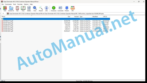
00 0186 371 0.pdf
00 0187 583 0.pdf
00 0298 367 0.pdf
00 0301 051 0.pdf
00 0303 482 0.pdf
00 0303 846 1.pdf
00 0298 367 0.pdf:
Introduction
Introduction
General information
Road Traffic Regulations
Identification Plate / Serial Number
Identification plate
Combine serial number
Engine serial number
Engine serial number
Engine serial number
Cutterbar serial number
Straw chopper serial number
Cab serial number
Safety rules
Safety Rules
Safety lock
Fire extinguisher
Battery isolating switch
Wheel chock (Not for all countries)
Straw guide apron
Safety Decals With Pictorials
Specifications
CLAAS DOMINATOR 58 / 48 Spezial
Threshing Equipment
Straw Walkers
Grain tank
Ground drive
Ground speeds
Traction wheel drive
Tyre sizes and pressures
Torque settings of wheel bolts
CLAAS DOMINATOR 58 / 48 Spezial
Combine dimensions
Wheel tread
Width over tyres
Wheel base
Ground clearance
Turning diameter conforming to DIN 70020
CLAAS DOMINATOR 58 / 48 Spezial
Transport position / working position
Safety features
Sectional View Of Combine
Description and function of the combine
Threshing parts
Straw walkers
Basic rules for combining
Prior to operation
Before Initial Operation
Driver’s Platform
Cab with ventilating system
Cab with ventilating system and air conditioner
Putting the air conditioner into operation
Cab with ventilating system and heating
Putting the heater into operation:
Problem, cause and / or remedy – Compressor-type air conditioner
Steering column
Ignition switch (S)
Repeating the starting procedure:
Vehicle information unit
Functions monitor:
Adjusting the steering column
Central terminal compartment
Hydraulic control unit (lift hydraulic system)
Instrument panel
Control levers
Swinging the grain tank unloading tube
Cutterbar height indicator
Adjusting the cutterbar height indicator:
Driver’s seat (standard version)
Adjusting the driver’s seat:
Driver’s seat (optional equipment)
Adjusting the driver’s seat:
Platform ladder
Front ladder
Rear ladder
Functions monitor
Work lights
Driving the Combine
Starting the engine
Starting the engine from cold:
Transmission of power
Gear selection and clutch
Stopping the combine
Driving behaviour
Drive carefully on public roads and when turning:
Foot brake
Stopping the engine
Operation – cutterbar
Attaching the Cutterbar
Levelling the cutterbar
Placing the cutterbar onto the ground:
Cutterbar clutch
Engaging the cutterbar:
Disengaging the cutterbar (quick stop):
Adjustment of cutterbar cylinders
Adjusting the cutterbar floatation springs
Adjustments at the Cutterbar
Crop dividers
Outer deflector
Inner deflector
Special crop divider (extra equipment)
Grain lifters
Removing the knife
Installing the knife
Adjusting the knife keeps
Knife timing
Spare knife
Cutterbar skids
Adjusting the tension of the reel drive chain
Adjusting the spring-Ioaded cylinder
Safety features:
Mechanical fore and aft reel adjustment
Hydraulic fore and aft reel adjustment
Reel tines:
Variable speed reel drive
Main table auger
Safety device:
Replacing knife sections in the field
Cutterbar trailer
Operation – basic machine
Feeder Housing
Safety feature:
Cutterbar reverse drive
Treshing Mechanism
Stone trap
Engaging the threshing mechanism
Disengaging the threshing mechanism
Concave adjustment
Basic setting:
Threshing drum
Cleaning the threshing parts
Drum variable speed pulleys
Slow speed threshing drum drive kit (Chain drive)
Unslugging the threshing drum
Filler rasp bars
Installing the filler rasp bars:
Deflector curtain
Straw Walkers and Cleaning
Straw walkers
Intensive separation system
Straw walker risers
Cleaning the straw walkers
Audible warning signal
Preparation floor
Pulling out the preparation floor
Cleaning fan
Adjusting the fan indicator:
Regulating the wind volume:
Adjusting wind direction:
Fan shutters for combining grass seed and other special crops
Adjusting the frogmouth sieves
Lower sieve
Changing the lower sieve
Dynamic sidehill levelling (3-D cleaning system)
Checking the returns:
Combine performance monitor
Straw walkers:
Sieve pan:
Adjusting monitor to crop type:
Adjusting the sensor sensitivity (Sieve pan sensor)
Adjusting the sensor sensitivity (Straw walker sensor)
Grain Delivery
Augers and auger troughs
Grain tank
Filling the grain tank:
Unloading the tank:
Hydraulic swing of grain tank unloading tube
Swinging the grain tank unloading tube in or out
Engaging the grain tank unloading augers
Disengaging the grain tank unloading augers
Safety feature
Safety feature adjustment
Clean-out door on grain tank discharge tube
Shear bolt – grain tank unloading system
Straw Chopper
Before using the straw chopper, check
Putting the straw chopper into operation
Adjusting the length of cut
Putting the straw chopper out of operation and changing over to windrowing straw
Changing the sieve while straw chopper is fitted
Moving the chopper back to front position
Deactivating the speed-loss monitor
Hitching the cutterbar trailer
Sieve and Threshing Chart
Sieve chart
Threshing chart
Problem, Cause and / or Remedy – Basic Machine
Threshing equipment
Straw walkers
Dynamic sidehill levelling 3-D cleaning unit
Grain tank
Maintenance – basic machine, cutterbar
Important Maintenance Instructions
Maintenance Schedules and Lubricants Charts
Maintenance Schedules
Lubricants Chart
Hydraulic System / Chassis
Lift hydraulic system
Tensioning the pump drive V-belt
Checking the oil level
Changing the hydraulic oil
Cleaning the screen filter
Replacing the paper filter cartridge
Oil filters (E and F), exploded view:
Bleeding the reel cylinders
Adjusting the ground drive clutch
Setting the bypass valve
Footbrakes / brake fluid
Transmissions
Change-speed transmission
Checking the oil level:
Oil change:
Final drives
Checking the oil level:
Oil change:
Adjusting the gear shift control
Drive Belts and Chains
Changing the variable speed belts
Threshing drum variable speed belt
Ground drive belt
Special tool:
Torque settings:
Fan variable speed belt
Adjusting the ground drive belt
Adjusting the spring-loaded cylinder (F):
Adjusting the belt guides:
Adjusting the ground drive variable speed pulleys:
Adjusting the threshing mechanism drive
Adjusting the spring-loaded tensioning cylinder (F):
Adjusting the spring-loaded return cylinder (S):
Adjusting the belt guides:
Adjusting the cutterbar drive
Adjusting spring-loaded cylinder (F):
Adjusting the belt guides:
Adjusting the V-belt clutch of unloading auger drive
Diagram of sieve pan drive belt
Straw walker drive
Tensioning the auger drive belt
Intensive separation system drive
Elevator Chains
Adjusting the tension of elevator chains
Clean grain elevator
Returns elevator
Feeder Housing
Greasing the feeder housing coupling forks
Tensioning the feed rake feeder chains
Cab / Compressor-type Air Conditioner
Cleaning the filters
Compressor-type air conditioner
Tensioning the compressor drive V-belt
Compressor-type air conditioner system preventive maintenance during prolonged shut-down
Cleaning the evaporator
Cleaning the condenser
Checking the refrigerant level
Function of the white float ball:
Function of blue indicator ball:
Replacing the filter receiver drier
Required quantity of refrigerant R 134 a
Maintenance work before the harvest
Fire extinguisher
Speed of straw walker crankshaft
Functions monitor
Straw Chopper
Changing the free-swinging knive
Removing the knives:
Installing the knives:
Changing the fixed stationary knives:
Adjusting the spring-loaded cylinder at the intermediate drive
Winter Storage Instructions for Combines
Maintenance – Engine
Important Maintenance Instructions
Maintenance Schedule and Lubricants Chart
Maintenance chart
Lubricants chart
Maintenance – Engine
Engine overview
Fuel system
Fuel pre-filter
Bleeding the fuel pre-filter (T):
Water separator / fuel pre-filter (extra equipment – replaces fuel pre-filter shown Fig._x0011_6)
Water separator / fuel pre-filter disassembled:
Fuel filter
Fuel filter
Bleeding the fuel system
Checking the engine oil level
Engine oil change
Draining oil
Oil filter
Filling in engine oil
Tensioning the V-belts
Tensioning the alternator / fan drive belt
Cooling System
Water drain plugs on the engine block
Water drain plugs on the engine block
Machines with cab heater:
Filling the cooling system with coolant
Overpressure
Coolant temperature
Warning signal
Radiator chaff screen
Cleaning rotor
Cleaning the radiator
Dry-type Air Cleaner
Warning device
Cleaning the air cleaner intake screen
Cleaning the air cleaner
Cleaning the dry-type air cleaner
Removing the main filter cartridge
Installing the main filter cartridge
Safety cartridge
Removing and installing the safety cartridge:
Replace the safety filter cartridge:
Electrical System
Alternator
Engine Problems, Cause and / or Remedy
Engine Winter Storage
Engine preservation
Operating the engine again
Lubrication chart
00 0301 051 0.pdf:
PROFI CAM 3
Table of contents
1 Introduction
1.1 Notes on the manual
1.1.1 Validity of manual
1.1.2 Information about this Operator’s Manual
1.1.3 Symbols and notes
1.1.4 Optional equipment
1.1.5 Qualified specialist workshop
1.1.6 Maintenance information
1.1.7 Warranty notes
1.1.8 Spare parts and technical questions
1.2 Intended use
1.2.1 Intended use
1.2.2 Reasonably foreseeable misuse
2.1 Identifying warnings
2.1.1 Hazard signs
2.1.2 Signal word
2.2 Safety rules
2.2.1 Meaning of Operator’s Manual
2.2.2 Observing safety decals and warnings
2.2.3 Optional equipment and spare parts
3 Product description
3.1 Overview and method of operation
3.1.1 How the PROFI CAM works
3.2 Identification plates and identification number
3.2.1 Position of identification plates
3.2.2 Explanation of PROFI CAM identification plate
3.3 Information on the product
3.3.1 CE marking
4 Operating and control elements
4.1 Camera system
4.1.1 Camera system monitor
4.2 Menu structure
4.2.1 Main menu
4.2.2
4.2.3
4.2.4
4.2.5
4.2.6
5 Technical specifications
5.1 PROFI CAM
5.1.1 Monitor
5.1.2 Camera
5.1.3 Switch box
5.1.4 Degree of protection against foreign bodies and water
6 Preparing the product
6.1 Shutting down and securing the machine
6.1.1 Switching off and securing the machine
6.2 Prior to operation
6.2.1 Carry out prior to operation
6.2.2 Installing the sun protection
6.2.3 Aligning the camera
6.2.4 Connecting the camera electrics
7 Operation
7.1 Monitor
7.1.1 Switching on the monitor
7.1.2 Calling up the menu
7.1.3 Setting a menu item
7.1.4 Setting the image orientation
7.1.5 Setting automatic screen darkening
7.1.6 Image mirroring
7.1.7 Setting the trigger view
7.1.8 Setting the follow-up time for trigger view
7.1.9 Setting the display mode
7.1.10 Activating/deactivating a display mode
8 Faults and remedies
8.1 Electrical and electronic system
8.1.1 Overview of problems on PROFI CAM camera system
8.1.2 Replacing the switch box fuse
9 Maintenance
9.1 Maintenance intervals
9.1.1 Every 10 operating hours or daily
9.2 Camera system
9.2.1 Checking the camera system for dirt
9.2.2 Cleaning the camera
9.2.3 Cleaning the switch box
9.2.4 Cleaning the monitor
10 Placing out of operation and disposal
10.1 General Information
10.1.1 Putting out of operation and disposal
11 Technical terms and abbreviations
11.1 Abbreviations
11.1.1 Units
11.1.2 Abbreviations
11.1.3 Technical terms
00 0303 482 0.pdf:
PROFI CAM 4
Table of contents
1 Introduction
1.1 Notes on the manual
1.1.1 Validity of manual
1.1.2 Information about this Operator’s Manual
1.1.3 Symbols and notes
1.1.4 Optional equipment
1.1.5 Qualified specialist workshop
1.1.6 Maintenance information
1.1.7 Notes on warranty
1.1.8 Spare parts and technical questions
1.2 Intended use
1.2.1 Intended use
1.2.2 Reasonably foreseeable misuse
2.1 Identifying warnings
2.1.1 Hazard signs
2.1.2 Signal word
2.2 Safety rules
2.2.1 Meaning of Operator’s Manual
2.2.2 Structural changes
2.2.3 Optional equipment and spare parts
2.2.4 Operation only following proper putting into operation
2.2.5 Technical status
2.2.6 Respecting technical limit values
Respecting technical limit values
2.2.7 Hazards when driving on roads and fields
3 Product description
3.1 Overview and method of operation
3.1.1 How the PROFI CAM works
3.2 Identification plates and identification number
3.2.1 Identification plates
3.3 Information on the product
3.3.1 CE marking
4 Operating and display elements
4.1 Camera system
4.1.1 Camera system monitor
4.1.2 CEBIS
4.2 Menu structure
4.2.1 Main menu
4.2.2
4.2.3
4.2.4
4.2.5
4.2.6
5 Technical specifications
5.1 PROFI CAM
5.1.1 Monitor
5.1.2 Camera
5.1.3 Switch box
6 Preparing the product
6.1 Switching off and securing the machine
6.1.1 Switching off and securing the machine
6.2 Prior to putting into operation
6.2.1 Carry out prior to operation
6.2.2 Installing the sun protection
6.2.3 Aligning the camera
7 Operation
7.1 Monitor
7.1.1 Switching on the monitor
7.1.2 Calling up the menu
7.1.3 Setting a menu item
7.1.4 Setting the image orientation
7.1.5 Setting automatic screen darkening
7.1.6 Image mirroring
7.1.7 Setting the trigger view
7.1.8 Setting the follow-up time for trigger view
7.1.9 Setting the display mode
7.1.10 Activating/deactivating a display mode
8 Faults and remedies
8.1 Electric and electronic system
8.1.1 Overview of problems on PROFI CAM camera system
9 Maintenance
9.1 Maintenance intervals
9.1.1 Every 10 operating hours or daily
9.2 Camera system
9.2.1 Checking the camera system for dirt
9.2.2 Cleaning the camera
9.2.3 Cleaning the switch box
9.2.4 Cleaning the monitor
10 Putting out of operation and disposal
10.1 General information
10.1.1 Putting out of operation and disposal
11 Technical terms and abbreviations
11.1 Abbreviations
11.1.1 Units
11.1.2 Abbreviations
11.1.3 Technical terms
00 0303 846 1.pdf:
DOMINATOR 40 WHEEL
Table of contents
1 To this Operator’s Manual
1.1 Notes on the manual
1.1.1 Validity of manual
1.1.2 Notes on the Operator’s Manual
1.1.3 Symbols and notices
1.1.4 Optional equipment
1.1.5 Qualified specialist workshop
1.1.6 Notes on maintenance
1.1.7 Notes on warranty
1.1.8 Technical specifications
1.1.9 Spare parts and technical questions
2.1 Intended use
2.1.1 Intended use
2.1.2 Reasonably foreseeable misuse
2.2 Safety rules
2.2.1 Operator’s Manual and other sources of information
Meaning of Operator’s Manual
2.2.2 Personnel qualification and organization
Requirements made on all persons working with the machine
2.2.3 Hazard for children
Children in danger
2.2.4 Modifications on the machine
Structural modifications
2.2.5 Additional equipment and spare parts
Additional equipment and spare parts
2.2.6 Workplace and persons travelling on the machine
Control of running machine
2.2.7 Technically flawless condition
Operation only following proper pre-delivery inspection
Operation only following proper putting into operation
Technically flawless condition of machine
Danger from damage on the machine
Respecting technical limit values
2.2.8 Hazard areas
Hazard areas
Standing between machine and front attachment
Objects flying away
Hazard while drive is engaged
Risk of injury on the universal drive shaft
Hazard from machine parts that continue rotating
2.2.9 Safety devices
Keeping the safety devices functional
2.2.10 Personal protective equipment
Personal protective equipment
Wearing suitable clothing
2.2.11 Safety markings
Keeping safety decals legible
2.2.12 Road safety
Hazards when driving on the road and on the field
Danger of tipping
Preparing the machine for road travel
Parking the machine safely
Unsupervised parking
Keeping the machine free of foreign objects
2.2.13 Operating utilities
Unsuitable operating utilities
Safe handling of operating and auxiliary utilities
Fuel is hazardous to your health
Environmental protection and disposal
2.2.14 Hazards caused by the field environment
Fire hazard
Possibly lethal electrocution from overhead lines
Behaviour in case of voltage flash-over of overhead lines and in case of lightning strike
2.2.15 Hazard sources on the machine
Electrocution from electric system
Noise may cause health problems
Vibrations may cause health problems
Liquids under pressure
Toxic exhaust gas
Hot surfaces
2.2.16 Hazard when climbing on and leaving the machine
Safe climbing on and leaving the machine
2.2.17 Hazards when working on the machine
Working on machine only after shutting it down
Maintenance and repair work
Lifted machine parts and loads
Danger from welding work
2.2.18 Checking the battery
Checking and charging the battery
2.3 Safety instructions in this manual
2.3.1 Identification of warning and danger signs
2.4 Safety decals on the machine
2.4.1 Front attachment
2.4.2 Notes on safety decals
2.4.3 Safety decals of engine
2.4.4 Safety decals of chassis
2.4.5 Safety decals of hydraulic system
2.4.6 Safety decals on operator’s platform
2.4.7 Safety decals of feed rake conveyor
2.4.8 Safety decals of crop discharge and straw discharge
2.4.9 Safety decals of grain delivery
2.4.10 Drives
2.5 Safety devices
2.5.1 Applying the feed rake conveyor safety lock
2.5.2 Releasing the feed rake conveyor safety lock
2.5.3 Securing the machine against rolling away
2.5.4 Switching the battery isolating switch on and off
2.5.5 Checking the fire extinguisher
3 Machine description
3.1 Overview and method of operation
3.1.1 Overview of DOMINATOR 40 Wheel, front and left
3.1.2 Overview of rear and right side of machine
3.1.3 Overview of front attachment
3.1.4 Working mode of the machine
3.1.5 Function of machine
3.1.6 Engine overview Ashok Leyland H3C4E7422
3.1.7 Overview of cooling units
3.2 Identification plates and vehicle identification number
3.2.1 Machine identification plate
Identification plate
4 Operating and control elements
4.1 Operator’s platform
4.1.1 Operator’s platform
4.1.2 Switch console and display panel
4.1.3 Drive lights, work lights, mirrors
4.1.4 Control levers
4.1.5 Lever for adjusting the diesel engine speed
4.1.6 Ignition switch
4.1.7 Steering column controls
4.1.8 Driver���s seat
5 Technical specifications
5.1 DOMINATOR 40 Wheel – type 551
5.1.1 Ashok Leyland H3C4E7422 diesel engine
5.1.2 Chassis
5.1.3 Chass wheel tread
5.1.4 Tyre Pressure
5.1.5 Clearance circle diameter
5.1.6 Turning circle diameter
5.1.7 Brake
5.1.8 Steering
5.1.9 Electric andnic equipment
5.1.10 Sound pressure level and vibrations
5.1.11 Feed rake conveyor
5.1.12 Threshing mechanism
5.1.13 Separation unit
5.1.14 Cleaning unit
5.1.15 Grain tank capacity
5.1.16 Dimensions of grain tank unloading tube in working position
5.1.17 Machine dimensions
5.1.18 Weights
6 Machine preparation
6.1 Switching off and securing the machine
6.1.1 Switch off and secure the machine
6.2 Accessing workplaces and maintenance places
Remove the front ladder
6.2.2 Adjusting the rear ladder
6.2.3 Access to the workplace and maintenance areas
6.3 Prior to putting into operation
6.3.1 Prior to initial operation
6.4 Setting of the machine for the operation
6.4.1 Setting the machine to grain harvest
6.4.2 Sieve chart
6.4.3 Threshing chart
6.4.4 Clean the machine for harvesting seeds
6.5 Diesel engine
6.5.1 Refuelling
6.6 Chassis
6.6.1 Removing and installing the wheels
6.6.2 Jacking up the machine
6.7.1 Checking the parking brake
6.7.2 Checking the foot brake
6.8 Hydraulic system
6.8.1 Identifying the hydraulic oil
6.9 Operator’s platform
6.9.1 Installing rear view mirrors
6.10 Feeder unit
6.10.1 Adjusting the feeder chain height
6.11 Threshing mechanism
6.11.1 Opening and closing the stone trap
6.11.2 Opening and closing the drum inspection cover
6.11.3 Checking the basic threshing concave setting
6.11.4 Installing or removing the disawner bars*
6.12 Separation
6.12.1 Removing and installing the deflector curtain
6.12.2 Installing and removing side risers
6.12.3 Installing and removing centre risers
6.13 Cleaning system
6.13.1 Removing the sieves
6.13.2 Installing the sieves
6.13.3 Assembly of Straw Walker
6.14 Grain delivery
6.14.1 Entering and leaving the grain tank
Entering and leaving the straw walker compartment
6.14.2 Adjusting the grain tank auger cover plates
6.14.3 Closing the service flap on the grain tank unloading tube
6.15 Assembly parts and bodywork
6.15.1 Opening / closing the side panels
6.15.2 Checking the reverse warning horn
7 Operation
7.1 Driving the machine
7.1.1 Preparing road travel
7.1.2 Preparing fieldwork
7.1.3 Manoeuvring the machine
7.1.4 Parking the machine
7.2 Diesel engine
7.2.1 Starting the diesel engine
Let the diesel engine warm up if the outside temperature is below 0 ��C.
7.2.2 Stop the diesel engine
7.2.3 Setting tsel engine speed
7.3 Chassis
7.3.1 Shifting gears
7.4.1 Braking the machine with the foot brake
7.4.2 Engaging the parking brake
7.4.3 Releasing the parking brake
7.4.4 Foot brake
7.4.5 Parking the machine
7.5 Cab and operator’s platform
7.5.1 Adjusting the driver’s seat
7.6 Steering
7.6.1 Steering 7.7 Grain Harvest
7.7.1 Fitting the crop dividers
7.8 Mower unit
7.8.1 Removing crop lifters
7.8.2 Adjusting the skid
7.8.3 Installing crop lifters
.8.4 Adjusting knife clips
7.9 Crop feeding
7.9.1 Adjusting the reel tines
7.9.2 Making the horizontal reel adjustment
7.9.3 Gap between reel tines and knife
7.9.4 Removal tines for Tur crop
7.9.5 Adjusting the stripper profile of the intake auger
7.9.6 Adjusting the position of the intake auger
7.9.7 Adjusting the intake auger fingers
7.9.8 Adjusting the reel peripheral speed
7.10 Feeder unit
7.10.1 Engaging and disengaging the feed rake conveyor
7.10.2 Raising or lowering the feed rake conveyor and the front attachment
7.11 Threshing mechanism
7.11.1 Engaging and disengaging the threshing mechanism
7.11.2 Adjusting the threshing concave
7.11.3 Checking the returns
7.12 Cleaning system
7.12.1 Basic Adjustment of the sieves
7.12.2 Adjusting the fan speed
7.13 Grain delivery
7.13.1 Opening and closing the grain tank cover
7.13.2 Swinging the grain tank unloading tube out and in
7.13.3 Engaging and disengaging grain tank unloading
8 Faults and remedies
8.1 8035 Ballast / Additional weight
8.1.1 Diesel engine
8.1.2 Draining the fuel from the fuel tank
8.1.3 Bleeding the fuel system
8.1.4 Diesel engine problems and remedies
8.2 Electrical and electonic system
8.2.1 Opening the basic central terminal compartment
8.2.2 Closing the basic central terminal compartment
8.2.3 Basic central terminal compartment
8.3 Front attachment fault and remedy
8.4 Feeder unit
8.4.1 Problems with and remedies for the feed rake conveyor
8.5 Threshing mechanism
8.5.1 Problems with and remedies for the threshing mechanism
8.5.2 Threshing drum
8.6 Separation
8.6.1 Problems with and remedies for the separation
8.7 Cleaning system
8.7.1 Problems with and remedies for the cleaning system
8.8 Grain delivery
8.8.1 Overview of problems with grain delivery
8.8.2 Installing the grain tank unloading shear bolt
9 Maintenance
9.1 Maintenance notes
9.1.1 Diesel engine
9.1.2 Cleaning the engine compartment and hazard areas
9.1.3 Belts
9.1.4 Variable-speed drives
9.1.5 Proper chain tension
9.1.6 Bolts
9.1.7 Lubrication
9.1.8 Cleanness of lubricants
9.1.9 Brake
9.1.10 Checking the wheels and tyres
9.1.11 Hydraulic system
9.1.12 Electric system
9.1.13 Protective guards
9.1.14 Spare parts
9.1.15 Unbalance
9.1.16 Welding work on combine harvester
9.1.17 Cleaning of surfaces with decals
9.1.18 Storing the machine
9.1.19 Coolant
9.2 Operating utilities
9.2.1 Lubricants
9.2.2 Coolant
9.2.3 Brake fluid
9.2.4 Hydraulic oils
9.3 Maintenance intervals
9.3.1 Before the harvest
9.3.2 After the first 10 operating hours
9.3.3 After the first 50 operating hours
9.3.4 After the first 100 operating hours
9.3.5 After the first 500 operating hours
9.3.6 Every 10 operating hours or daily
9.3.7 Every 50 operating hours
9.3.8 Every 100 operating hours
9.3.9 Every 250 operating hours
9.3.10 Every 500 operating hours or annually
9.3.11 Every 2 years
9.3.12 After the harvest
9.4 Diesel engine
9.4.1 Cleaning the diesel engine
9.4.2 Draining the fuel
9.4.3 Cleaning the cooling unit
9.4.4 Replacing the fuel filter
9.4.5 Checking the diesel engine oil level
9.4.6 Checking the radiator coolant level
9.4.7 Topping up the diesel engine oil
9.4.8 Changing the diesel engine oil and oil filter
9.4.9 Checking the diesel engine coolant level
9.4.10 Checking the coolant anti-freeze effect
Use of ready-mixed coolant
Use of concentrated corrosion protection / anti-freeze agent
9.4.11 Draining the diesel engine coolant
9.4.12 Topping up diesel engine coolant
9.4.13 Opening the radiator screen
9.4.14 Cleaning the radiator screen
9.4.15 Cleaning and changing the diesel engine air filter
9.4.16 Changing the coolant hoses
9.4.17 Retightening the coolant hose clamps
9.5 Chassis
9.5.1 Checking the wheels and tyres
9.5.2 Checking the wheel tightening torques
Drive axle
Steering axle
9.5.3 Cleaning the drive axle manual gearbox
9.5.4 Checking the oil level of the drive axle final drive
9.5.5 Drain the drive axle final drive oil
9.5.6 Top up the drive axle final drive oil
9.5.7 Checking the oil level of the drive axle manual gearbox
9.5.8 Drain the drive axle manual gearbox oil
9.5.9 Topping up the drive axle manual gearbox oil
9.6.1 Checking the brake fluid level
9.7 Drives
9.7.1 Adjusting the drives
9.7.2 Fitting and adjusting chain (K1) and (K2)
9.7.3 Removing chain (K3) and (K4)
9.7.4 Fitting and adjusting chain (K3) and (K4)
9.7.5 Removing belt (R5)
9.7.6 Fitting and adjusting belt (R5)
9.7.7 Removing belt (R6)
9.7.8 Fitting and adjusting belt (R6)
9.7.9 Removing belt (R7)
9.7.10 Installing belt (R7)
9.7.11 Adjusting belt (R7)
9.7.12 Removing belt (R8)
9.7.13 Installing belt (R8)
9.7.14 Adjusting belt (R8)
9.7.15 Removing belt (R9) and (R10)
9.7.16 Installing belt (R9) and (R10)
9.7.17 Removing belt (R11)
9.7.18 Fitting and adjusting belt (R11)
9.7.19 Removing chain (K12)
9.7.20 Installing chain (K12)
9.7.21 Adjusting chain (K12)
9.7.22 Removing belt (R13)
9.7.23 Assembly and Alignment of belt (R13)
9.7.24 Removing belt (R14)
9.7.25 Fitting and adjusting belt (R14)
9.7.26 Removing belt (R15)
9.7.27 Fitting and adjusting belt (R15)
9.7.28 Removing chain (K16)
9.7.29 Fitting and adjusting Chain (K16)
9.7.30 Removing chain (K17)
9.7.31 Fitting and adjusting chain (K17)
9.8 Hydraulic system
9.8.1 Relieving the pressure accumulator
9.8.2 Checking the hydraulic hoses
9.8.3 Checking the hydraulic system oil level
9.8.4 Changing the hydraulic system oil / oil filter
9.9 Electrical and electronic system
9.9.1 Disconnecting the battery isolating switch
9.9.2 Engine Management System
9.9.3 Checking the battery electrolyte level
9.10 Feeder unit
9.10.1 Adjusting the feeder chains
9.10.2 Adjusting the reel and auger chain slip clutch
9.10.3 Cleaning the stone strap
9.11 Threshing mechanism
9.11.1 Adjusting the returns elevator and returns drive elevator chain
9.11.2 Cleaning the threshing housing
9.12 Separation
9.12.1 Checking the deflector curtain
9.12.2 Cleaning the walker housing
9.12.3 Replacing walker shaft assembly
9.13 Grain delivery
9.13.1 Adjusting the grain elevator and grain elevator drive chain
9.13.2 Clean the auger troughs
9.13.3 Clean the grain tank
9.13.4 Adjusting the grain tank unloading tube support
9.14 Assembly parts and bodywork
9.14.1 Cleaning the machine
9.14.2 Cleaning rear hood in Tur crop
9.14.3 Checking the gearbox for leaks
9.14.4 Checking the hydraulic system for leaks
9.15 Lubrication plan
9.15.1 Lubrication points – 10 h Left
9.15.2 Lubrication points – 10 h right
9.15.3 Lubrication points – 50 h left
9.15.4 Lubrication points – 50 h right
9.15.5 Lubrication points – 100 h left
9.15.6 Lubrication points – 100 h right
10 Putting out of operation and disposal
10.1 General information
10.1.1 Placing out of operation and disposal
11 Technical terms and abbreviations
11.1 Terms and explanations
11.1.1 Abbreviations
11.1.2 Technical terms
John Deere Repair Technical Manual PDF
John Deere Parts Catalog PDF
John Deere Harvesters 8500 and 8700 Parts Catalog CPCQ24910 Spanish
John Deere Repair Technical Manual PDF
John Deere Repair Technical Manual PDF
John Deere Repair Technical Manual PDF
John Deere Repair Technical Manual PDF
John Deere Application List Component Technical Manual CTM106819 24AUG20
John Deere Repair Technical Manual PDF
John Deere Repair Technical Manual PDF
John Deere Repair Technical Manual PDF
John Deere Repair Technical Manual PDF
John Deere POWERTECH E 4.5 and 6.8 L Diesel Engines TECHNICAL MANUAL 25JAN08

