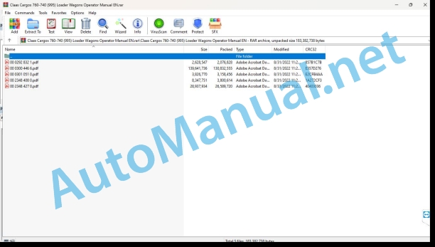
Claas Cargos 760-740 (995) Loader Wagons Operator Manual EN
$50.00
- Model: Cargos 760-740 (995) Loader Wagons
- Type Of Manual: Operator Manual
- Language: EN
- Format: PDF(s)
- Size: 159 MB
File List:
00 0292 832 1.pdf
00 0300 446 6.pdf
00 0301 051 0.pdf
00 2348 408 0.pdf
00 2348 427 0.pdf
00 0292 832 1.pdf:
OPERATOR
Table of contents
1 To this Operator’s Manual
1.1 Notes on the manual
1.1.1 Validity of the manual
1.1.2 Using the manual
1.1.3 Symbols and notes
1.1.4 Technical specifications
2 Safety
2.1 Safety rules
2.1.1 Particularly important
2.1.2 Intended use
2.1.3 Reasonably foreseeable misuse
2.1.4 General safety and accident prevention regulations
3 Product description
3.1 Overview and method of operation
3.1.1 OPERATOR overview
3.1.2 OPERATOR mode of operation
3.2 Identification plates and identification numbers
3.2.1 Spare parts and technical questions
3.2.2 OPERATOR identification plate
4 Operating and display elements
4.1 CLAAS OPERATOR
4.1.1 Terminal
4.1.2 Terminal program
4.1.3 Menu overview
4.1.4 Information menu
4.1.5 Settings menu
4.1.6 Time menu
4.1.7 Diagnosis menu
4.1.8 Language and units menu
5 Technical specifications
5.1 CLAAS OPERATOR
5.1.1 Specification
6 Operation
6.1 Switching the OPERATOR on and off
6.1.1 Switching on the OPERATOR
6.1.2 Selecting an application
6.1.3 Switching off the OPERATOR
6.2 Terminal settings
6.2.1 Adjusting the screen and volume
Day mode
Night mode
6.2.2 Adjusting the date and time
6.2.3 Displaying the diagnosis information
On-board voltage display (1)
Enabling the speed signal (2)
Displaying the CLAAS ISOBUS ECU address and name (3)
6.2.4 Setting the language and display formats
Setting the language
Setting the display formats
7 Maintenance
7.1 Maintenance
7.1.1 Daily
8 Putting out of operation and disposal
8.1 General information
8.1.1 Putting out of operation and disposal
9 Technical terms and abbreviations
9.1 Terms and explanations
9.1.1 Technical words
9.1.2 Abbreviations
00 0300 446 6.pdf:
CARGOS 760CARGOS 750CARGOS 740
Table of contents
1 Introduction
1.1 General information
1.1.1 Validity of the manual
1.1.2 Information about this Operator’s Manual
1.1.3 Symbols and notes
1.1.4 Optional equipment
1.1.5 Qualified specialist workshop
1.1.6 Maintenance notes
1.1.7 Notes on warranty
1.1.8 Spare parts and technical questions
1.2 Intended use
1.2.1 Intended use
1.2.2 Reasonably foreseeable misuse
2 Safety
2.1 Identifying warnings
2.1.1 Hazard signs
2.1.2 Signal word
2.2 Safety rules
2.2.1 Importance of Operator’s Manual
2.2.2 Observe the safety decals and warnings
2.2.3 Requirements for all persons working with the machine
2.2.4 Children in danger
2.2.5 Hazard areas
2.2.6 Presence between tractor and machine
2.2.7 Persons riding on the machine
2.2.8 Hitching the tractor to the machine
2.2.9 Danger of injury from rotating shafts
2.2.10 Structural changes
2.2.11 Optional equipment and spare parts
2.2.12 Controlling the tractor when it is running
2.2.13 Operation only after proper putting into operation
2.2.14 Technical condition
2.2.15 Danger from damage to the machine
2.2.16 Complying with technical limit values
2.2.17 Danger from continued running of machine parts
2.2.18 Keeping the safety devices functional
2.2.19 Personal protective equipment
2.2.20 Wearing suitable clothing
2.2.21 Removing dirt and loose objects
2.2.22 Preparing the machine for road travel
2.2.23 Risks when driving on the road and in the field
2.2.24 Parking the machine safely
2.2.25 Unsupervised parking
2.2.26 Unsuitable operating utilities
2.2.27 Safe handling of operating and auxiliary utilities
2.2.28 Environmental protection and disposal
2.2.29 Fire prevention
2.2.30 Lethal electrocution from overhead lines
2.2.31 Behaviour in case of voltage flashover from overhead lines and of lightning strikes
2.2.32 Electrocution by electrical system
2.2.33 Pressurised fluids
2.2.34 Compressed air
2.2.35 Hot surfaces
2.2.36 Working on machine only after shutting it down
2.2.37 Maintenance work and repairs
2.2.38 Raised machine parts and loads
2.2.39 Danger from welding work
2.3 Safety marking
2.3.1 Layout of safety decals
2.3.2 Safety decals on the machine
3 Machine description
3.1 Overview and method of operation
3.1.1 Overview of machine with tridem axle assembly
3.1.2 Overview of machine with tandem axle assembly
3.1.3 Function of machine
3.1.4 Function of articulated drawbar
Hitched machine
Unhitched machine
3.2 Safety devices
3.2.1 Parking brake
3.2.2 Parking brake
3.2.3 Stand
3.2.4 Wheel chocks
3.3 Optional equipment
3.3.1 CEMIS 700*
3.3.2 EASY on board App*
Requirements made on the tablet (not included in the shipping package)
3.3.3 TELEMATICS ON IMPLEMENT*
3.3.4 Extension cable*
3.3.5 ISOBUS connecting cable*
3.3.6 Extension cable*
3.3.7 Hydraulic coupling as per ISO 16028*
3.3.8 Slip yoke*
3.3.9 Proportioning roller unit*
3.3.10 Tail section* with removed proportioning rollers
3.3.11 LED work lights*
3.3.12 Side marker lights*
3.3.13 External load weight display*
3.3.14 Loading space cover*
3.3.15 Sequential control*
3.3.16 Battery cable*
3.3.17 ISOBUS battery cable*
3.3.18 Load weight display*
3.3.19 Electronic-hydraulic forced steering system*
3.3.20 Cuna F3* hitch eye
3.4 Identification plates and vehicle identification number
3.4.1 Machine identification plate
3.4.2 Machine identification plate
3.4.3 Identification plate of the drawbar
3.4.4 Identification plate of the axles
3.4.5 Identification plate of compressed air brake
3.5 Information on the machine
3.5.1 Stickers on the machine
4 Operating and display elements
4.1 Controls
4.1.1 External control panel
4.1.2 External control panel
4.1.3 Parking brake crank
4.1.4 Control unit
4.1.5 Tailgate ball valve
4.1.6 Tailgate and hydro-pneumatic chassis ball valve
4.1.7 Tailgate ball valve
4.1.8 Ball valve on the steered trailing axle’s steering cylinder
4.1.9 Steered axle ball valves*
4.1.10 Hydro-pneumatic chassis ball valves*
Driving height
Suspension
4.1.11 Sequential control* ball valve
4.2 Display elements
4.2.1 Articulated drawbar scale
4.2.2 Tailgate pressure gauge
4.2.3 Mechanical-hydraulic forced steering system pressure gauge*
Machine with tridem axle assembly
Machine with tandem axle assembly
4.2.4 Sequential control* pressure gauge
4.3 Menu structure of terminal*
4.3.1 Display variants
4.3.2 Screen overview
4.3.3 Overview of
4.3.4
Description of soft keys in
Description of symbols in the data field
4.3.5
Description of soft keys in
Description of symbols in the data field
4.3.6
Description of soft keys in
Description of symbols in the data field
4.3.7
Description of soft keys in
Description of symbols in the data field
4.3.8 Settings menu
Description of soft keys in
Description of symbols in the data field
Description of symbols in the
Description of symbols in the
Description of symbols in the
Description of symbols in the
Description of symbols in the
Description of symbols in the
Description of symbols in the
Description of symbols in the
4.3.9
Description of soft keys in
Description of symbols in the data field
4.3.10 Status bar
5 Technical specifications
5.1 CARGOS 760
5.1.1 Dimensions
5.1.2 Loading space cover dimensions*
5.1.3 Dimensions of platform gate raiser*
5.1.4 Weights
5.1.5 Tyre pressure
5.1.6 Requirements of the tractor
5.1.7 Electrical system
5.1.8 PTO speed
5.1.9 Sound pressure level
5.2 CARGOS 750
5.2.1 Dimensions
5.2.2 Loading space cover dimensions*
5.2.3 Dimensions of platform gate raiser*
5.2.4 Weights
5.2.5 Tyre pressure
5.2.6 Requirements of the tractor
5.2.7 Electrical system
5.2.8 PTO speed
5.2.9 Sound pressure level
5.3 CARGOS 740
5.3.1 Dimensions
5.3.2 Loading space cover dimensions*
5.3.3 Dimensions of platform gate raiser*
5.3.4 Weights
5.3.5 Tyre pressure
5.3.6 Requirements of the tractor
5.3.7 Electrical system
5.3.8 PTO speed
5.3.9 Sound pressure level
5.4 Operating utilities
5.4.1 Lubricants
6 Machine preparation
6.1 Switching off and securing the machine
6.1.1 Switching off and securing the tractor and machine
6.2 Assembling the machine
6.2.1 Fitting the drive shaft* to the machine
6.2.2 Connecting the ISOBUS connecting cable*
6.2.3 Sliding the wheel chocks into their brackets
6.3 Accessing workplaces and maintenance spaces
6.3.1 Overview of maintenance areas
6.3.2 Accessing and leaving the loading space through the tailgate
6.3.3 Accessing and leaving the loading space through the access hatch*
Accessing the loading space
Leaving the loading space
6.3.4 Front covers
Opening the front covers
Closing the front covers
6.3.5 Rear left covers
Opening the rear left covers
Closing the rear left covers
6.3.6 Rear right covers
Opening the rear right covers
Closing the rear right covers
6.4 Adapting the tractor
6.4.1 Checking the protective guard on the tractor PTO shaft
6.4.2 Tractor hitching for Cuna F3 hitch eye
6.4.3 Tractor hitching for forced steering system*
6.4.4 Configuring the tractor air brake system
6.4.5 Installing the control unit
6.4.6 Installing the COMMUNICATOR II*
6.4.7 Installing the OPERATOR*
6.5 Using the tractor terminal
6.5.1 Using the tractor terminal
6.5.2 Tractor terminal and joystick
6.5.3 Using the COMMUNICATOR II* and joystick
6.5.4 Converting the FENDT Vario tractor terminal
6.6 Adapting the machine
6.6.1 Checking the length of the drive shaft*
Shortest operating position of universal drive shaft
Longest operating position of universal drive shaft
6.6.2 Adapting the length of the drive shaft*
6.6.3 Adapting the hydraulic system
Closed hydraulic system (constant-pressure or load sensing)
Open hydraulic system (without load sensing)
6.6.4 Adjusting the tailgate closing pressure*
6.6.5 Adjusting the articulated drawbar
6.6.6 Adjusting the chassis height*
Raising the chassis on the right
Raising the chassis on the left
Lowering the chassis on the right
Lowering the chassis on the left
6.6.7 Relocating the drawbar sensor* lever
6.6.8 Adjusting the electronic-hydraulic forced steering system*
Check basic setup
Adjusting the tow bar
Avoiding overstretching the sensor
6.6.9 Removing the proportioning roller unit*
6.6.10 Initialising the drawbar position
6.7 Hitching the machine
6.7.1 Connecting the lighting
6.7.2 Connecting the control unit
6.7.3 Connecting CEMIS 700*
6.7.4 Connecting COMMUNICATOR II*
6.7.5 Connecting the OPERATOR*
6.7.6 Connecting the tablet*
6.7.7 Connecting the ISOBUS battery cable*
6.7.8 Connecting the ISOBUS battery cable*
6.7.9 Connecting the ISOBUS battery cable*
6.7.10 Connecting the hydraulic hose lines
Connecting the hydraulic hoses of the articulated drawbar
Connecting the hydraulic hoses of the floor conveyor
Connecting the hydraulic hoses of the floor conveyor
Connecting the hydraulic hose of the steered trailing axle
Connecting the hydraulic hoses of the tailgate
Connecting the hydraulic hoses of the loading space cover*
6.7.11 Connecting the hydraulic hose lines
Connecting the hydraulic hoses with the hydraulic system closed (with load sensing)
Connecting the hydraulic hoses with the hydraulic system open (without load sensing)
Connecting hydraulic hose P1
6.7.12 Remove safety lock*
6.7.13 Hitching the articulated drawbar
6.7.14 Raising the stand
6.7.15 Coupling the electronic-hydraulic forced steering system*
6.7.16 Hitching the mechanical-hydraulic forced steering system*
6.7.17 Fitting the drive shaft*
6.7.18 Connecting the compressed air brake*
6.7.19 Connecting the hydraulic brake*
6.7.20 Connecting the breakaway brake*
6.7.21 Removing the wheel chocks
6.7.22 Releasing the parking brake
6.7.23 Releasing the parking brake
6.8 Unhitching the machine
6.8.1 Applying the parking brake
6.8.2 Applying the parking brake
6.8.3 Positioning the wheel chock at the wheel
6.8.4 Swinging down the jack stand
6.8.5 Removing the drive shaft*
6.8.6 Unhitching the articulated drawbar
6.8.7 Unhitching the electronic-hydraulic forced steering system*
6.8.8 Unhitching the mechanical-hydraulic forced steering system*
6.8.9 Fit safety lock*
6.8.10 Disconnecting the hydraulic hose lines
6.8.11 Disconnecting the hydraulic hose lines
6.8.12 Disconnecting the hydraulic brake* from the tractor
6.8.13 Disconnecting the breakaway brake*
6.8.14 Disconnecting the compressed air brake*
6.8.15 Disconnecting the lighting
6.8.16 Disconnecting the control unit
6.8.17 Disconnecting CEMIS 700*
6.8.18 Disconnecting the COMMUNICATOR II*
6.8.19 Disconnecting the OPERATOR*
6.8.20 Disconnecting the tablet*
6.9 Prepare road travel
6.9.1 Move machine to transport position
6.9.2 Adjusting the underride guard*
6.9.3 Activating the suspension of the hydro-pneumatic chassis*
6.10 Preparing fieldwork
6.10.1 Deactivating the suspension of the hydro-pneumatic chassis*
6.11 Loading the machine
6.11.1 Manoeuvring the machine
6.11.2 Loading and lashing down the machine
7 Operation without terminal
7.1 Driving on the road
7.1.1 Driving on public roads
7.2 Fieldwork
7.2.1 Observe the following during field work
7.2.2 Unlocking the steered trailing axle
7.3 Loading the machine
7.3.1 Moving the articulated drawbar to the loading position
Loading position for loading from the front
Loading position for loading from the left or right
7.3.2 Opening the loading space covers*
7.3.3 Switching on the work lights
7.4 Unloading the machine
7.4.1 Raising the articulated drawbar to the unloading position
7.4.2 Opening the tailgate
7.4.3 Engaging the proportioning rollers*
7.4.4 Switching on the floor conveyor drive
7.4.5 Adjusting the floor conveyor speed
7.4.6 Reversing the floor conveyor*
7.4.7 Disengaging the proportioning roller*
7.4.8 Switching off the floor conveyor drive
7.4.9 Closing the tailgate
7.5 Move machine to transport position
7.5.1 Closing the loading space covers*
7.5.2 Switching off the work lights
7.5.3 Moving the articulated drawbar to the transport position
7.5.4 Activating hydraulic drawbar suspension*
7.5.5 Locking the steered trailing axle
8 Control by terminal
8.1 ISOBUS and OPERATOR control unit
8.1.1 Description
8.2 CEMIS 700
8.2.1 CEMIS 700* recommendations
8.2.2 CEMIS 700* operation
8.2.3 Calling up the menu
8.2.4 Calling up the sub-menu
8.3 COMMUNICATOR II
8.3.1 COMMUNICATOR II* recommendations
8.3.2 Operating the COMMUNICATOR II*
8.3.3 Calling up the menu
8.3.4 Calling up the sub-menu
8.4 OPERATOR
8.4.1 OPERATOR* recommendations
8.4.2 Operating the OPERATOR*
8.5 EASY on board App
8.5.1 EASY on board App* recommendations
8.5.2 Operation of the EASY on board App*
8.5.3 Calling up the menu
8.5.4 Calling up the sub-menu
8.6 Fieldwork settings
8.6.1 Switching on the terminal
8.6.2 Starting the control program
8.6.3 Creating a job
8.6.4 Switching data entry on and off
8.6.5 Changing the opening angle of the tailgate
8.6.6 Changing the floor conveyor speed for unloading
8.6.7 Changing the lift axle* setting for loading
8.6.8 Changing the lift axle* setting for unloading
8.6.9 Adjusting the automatic unladen weight measurement
8.6.10 Changing the loading automatic mode preselection
8.6.11 Displaying and changing the lighting configuration
Displaying the lighting configuration
Changing the lighting configuration
8.6.12 Changing the steered trailing axle settings
Adjusting the speed-dependent axle lock
Setting the silo mode
8.6.13 Changing the settings for the electronic-hydraulic forced steering system*
Setting the silo mode
Adjusting the adaptive articulation angle warning
Saving the end stops of the adaptive articulation angle warning
Adjusting the dynamic steering line shift
8.6.14 Displaying and changing the articulated drawbar positions
Positioning the articulated drawbar according to the default value
Changing the default value of the articulated drawbar
8.6.15 Displaying and changing the loading space cover* positions
Positioning the loading space cover according to the default value
Changing the default value of the loading space covers
8.6.16 Restoring the factory settings
8.6.17 Deleting cached graphic objects in the control terminal
8.7 Using the
8.7.1 Available functions
8.7.2 Application example of COMMUNICATOR II*
8.7.3 Application example of AXION / ARION
8.7.4 Application examples of FENDT
8.8 Driving on the road
8.8.1 Driving on public roads
8.9 Fieldwork
8.9.1 Observe the following during field work
8.9.2 Unlocking the steered trailing axle
8.9.3 Lowering the lift axle*
8.9.4 Centring the steering axles*
Centring the steering axles from the
Centring the steering axles from the
8.9.5 Activating offset mode*
Activating the offset mode via the
Activating the offset mode via the
8.9.6 Activating the manual mode*
Deactivating the manual mode
8.10 Loading the machine
8.10.1 Moving the machine to the loading position
Preselecting a soft key
Carrying out the function
8.10.2 Changing the loading mode
Activating loading from the left or right
Activating loading from the front (chopping start)
8.10.3 Activating the loading bay cover* automatic mode
Opening the loading bay cover* automatically according to the preset
Opening the loading bay cover* fully
8.10.4 Switching on the work lights
8.10.5 Switching the external load weight display* on and off
8.10.6 Finishing automatic loading
8.11 Unloading the machine automatically
8.11.1 Activating automatic unloading
Calling up via the
Calling up via the
8.11.2 Changing the floor conveyor speed
Entering a value in the entry field
Changing the speed by means of keys
8.11.3 Starting manual unladen weight measurement
8.11.4 Finishing automatic unloading
8.12 Moving the machine to transport position automatically
8.12.1 Activating the transport position after loading
8.12.2 Activating the transport position after unloading
8.13 Unloading the machine manually
8.13.1 Moving the machine to the unloading position
8.13.2 Switching on the work lights
8.13.3 Opening the tailgate
8.13.4 Engaging the proportioning rollers*
8.13.5 Switching on the floor conveyor drive
8.13.6 Changing the floor conveyor speed
8.13.7 Disengaging the proportioning roller*
8.13.8 Switching off the floor conveyor drive
8.13.9 Closing the tailgate
8.13.10 Starting manual unladen weight measurement
8.14 Moving the machine to transport position manually
8.14.1 Lifting the lift axle*
8.14.2 Closing the loading bay cover*
8.14.3 Moving the articulated drawbar to the transport position
8.14.4 Activating hydraulic drawbar suspension*
8.14.5 Switching off the work lights
8.14.6 Locking the steered trailing axle
8.14.7 Activating road travel mode*
Activating the road travel mode via the
8.14.8 Deactivating offset mode*
8.15 Finishing fieldwork
8.15.1 Displaying and printing job data
Order-dependent counters
Non-order-dependent counter
Printing the job data*
8.15.2 Switching off the terminal
8.16 Initialising
8.16.1 Applications
8.16.2 Learning the articulated drawbar end stops
8.16.3 Learning the loading space cover* end stops
8.16.4 Learning the tailgate end stops
8.16.5 Initialising the electronic-hydraulic forced steering system*
Saving straight-line stability
8.16.6 Faults when learning the end stops
9 Faults and remedies
9.1 Overview of problems
9.1.1 Overview of problems on the machine
9.2 Electric and electronic system
9.2.1 Control unit cannot be switched on
9.2.2 Control unit cannot be switched on
9.3 Chassis
9.3.1 Changing the wheel
9.4 Steering
9.4.1 Steered axle fails to contribute to steering
Checking the cylinder
Adjusting the straight-ahead travel of the machine
9.5 Emergency operation
9.5.1 Work steps prior to emergency operation
9.5.2 Operating hydraulic valves manually
9.5.3 Emergency operation of the sequential control*
9.5.4 Emergency operation of mechanical-hydraulic forced steering system*
9.6 ISOBUS fault messages
9.6.1 Maintenance alarm
9.6.2 Alarm messages
9.6.3 Sensor installation positions
9.6.4 Sensor fault
9.6.5 Proportioning rollers* speed sensor fault when unloading
9.6.6 Undervoltage
9.6.7 Access hatch
9.6.8 Articulation angle warning
9.6.9 Fault in the electronic-hydraulic forced steering system*
9.6.10 Fault code table
9.6.11 Fault code table of electronic-hydraulic forced steering system*
10 Maintenance
10.1 Maintenance interval overview
10.1.1 Before the harvest
10.1.2 After the first 10 operating hours
10.1.3 After the first 50 operating hours
10.1.4 After the first 200 operating hours
10.1.5 Every 8 operating hours or daily
10.1.6 Every 20 operating hours
10.1.7 Every 50 operating hours
10.1.8 Every 250 operating hours
10.1.9 Every 500 operating hours or annually
10.1.10 Every 1000 operating hours or every 2 years
10.1.11 Every 5 years
10.1.12 After the harvest
10.2 Gearbox
10.2.1 Checking the gearbox for leaks
10.2.2 Checking the oil level in the proportioning roller gearbox*
10.2.3 Changing the oil in the proportioning roller gearbox*
10.2.4 Checking the oil level in the floor conveyor gearbox
10.2.5 Changing the oil in the floor conveyor gearbox
10.3 Clutch
10.3.1 Checking the overload clutch*
10.4 Drive shaft*
10.4.1 Servicing the universal drive shaft*
10.4.2 Removing and installing the universal drive shaft guard*
10.5 Chassis
10.5.1 Check the tyre pressure
10.5.2 Check the wheel nuts
10.5.3 Checking the wheel bearing play
10.5.4 Changing the grease of hub bearings
10.5.5 Checking the steered axle steering hinges
10.5.6 Checking the steered axle gas strut
10.5.7 Checking the shock absorbers
10.5.8 Checking the steered axle control cylinder
10.5.9 Checking the steering rod
10.5.10 Lubricating the steered trailing axle’s steering cylinder
10.6 Mechanical chassis 10 t
10.6.1 Check the axle suspension
10.6.2 Checking the pendulum arm
10.6.3 Checking the reaction bars
10.6.4 Checking the leaf spring bolts
10.7 Mechanical chassis 9 t
10.7.1 Check the axle suspension
10.7.2 Checking the pendulum arm
10.7.3 Checking the reaction bars
10.7.4 Checking the leaf spring bolts
10.8 Hydro-pneumatic chassis
10.8.1 Check the alignment of body
10.8.2 Checking the cylinder fastening*
10.8.3 Checking the axle suspension*
10.8.4 Checking the joint pins*
10.8.5 Checking the machine suspension*
10.8.6 Checking the leaf springs
10.9 Brake
10.9.1 Carry out a functional check of the brake system
10.9.2 Performing a visual check of the brake system
10.9.3 Check the brake linings
10.9.4 Checking the brake lever path of compressed air brake*
Checking the brake lever path
Adjusting the service brake slack adjusters
10.9.5 Drain the compressed air reservoir*
Cleaning the drain valve
10.9.6 Check the brake cylinders
10.9.7 Clean the pipe filter*
10.10 Steering
10.10.1 Check the hydraulic pressure of mechanical-hydraulic forced steering system
Filling steered axle 1
Filling steered axle 3
Venting the hydraulic system
10.11 Hitch
10.11.1 Checking the screws on the stand
10.11.2 Checking the articulated drawbar hitch
Towing ball and socket joint
Hitch eye (ring 50 mm)
Hitch eye (Cuna F3)
10.11.3 Check the forced steering system* hitching
10.12 Drives
10.12.1 Maintaining chains
10.12.2 Checking the drive chains of proportioning rollers*
10.12.3 Tensioning the drive chains of proportioning rollers*
10.13 Hydraulic system
10.13.1 Reducing the pressure in the hydraulic system
10.13.2 Checking the hydraulic hoses
10.13.3 Checking the accumulator
10.14 Electric and electronic system
10.14.1 Adjusting the speed sensor of the proportioning rollers
10.14.2 Adjust the tailgate position sensor
10.14.3 Checking the lighting
10.14.4 Checking the lights
10.15 Tailgate
10.15.1 Adjusting the locking device on the tailgate
10.15.2 Adjusting the distance on the tailgate
10.16 Floor conveyor
10.16.1 Checking the conveyor slats
10.16.2 Checking and tensioning the floor conveyor chains
Checking the floor conveyor chains
Tensioning the floor conveyor chains
10.16.3 Removing chain links
10.17 Assembly parts and machine body
10.17.1 Check the wheel chocks
10.17.2 Remove any crop residues
Chassis cylinder*
10.17.3 Check the fittings
10.17.4 Clean the machine
10.17.5 Preserve the machine
10.18 Lubrication plan
10.18.1 Lubricating grease points every 20 operating hours
10.18.2 Lubricate lubrication points every 50 operating hours
10.18.3 Lubricating grease points every 500 operating hours
11 Putting out of operation and disposal
11.1 General information
11.1.1 Decommissioning and disposal
12 EC declaration of conformity
12.1 CARGOS 760 / 750 / 740
12.1.1 EC declaration of conformity
13 Technical terms and abbreviations
13.1 Terms and explanations
13.1.1 Abbreviations
13.1.2 Technical terms
00 0301 051 0.pdf:
PROFI CAM 3
Table of contents
1 Introduction
1.1 Notes on the manual
1.1.1 Validity of manual
1.1.2 Information about this Operator’s Manual
1.1.3 Symbols and notes
1.1.4 Optional equipment
1.1.5 Qualified specialist workshop
1.1.6 Maintenance information
1.1.7 Warranty notes
1.1.8 Spare parts and technical questions
1.2 Intended use
1.2.1 Intended use
1.2.2 Reasonably foreseeable misuse
2 Safety
2.1 Identifying warnings
2.1.1 Hazard signs
2.1.2 Signal word
2.2 Safety rules
2.2.1 Meaning of Operator’s Manual
2.2.2 Observing safety decals and warnings
2.2.3 Optional equipment and spare parts
3 Product description
3.1 Overview and method of operation
3.1.1 How the PROFI CAM works
3.2 Identification plates and identification number
3.2.1 Position of identification plates
3.2.2 Explanation of PROFI CAM identification plate
3.3 Information on the product
3.3.1 CE marking
4 Operating and control elements
4.1 Camera system
4.1.1 Camera system monitor
4.2 Menu structure
4.2.1 Main menu
4.2.2
4.2.3
4.2.4
4.2.5
4.2.6
5 Technical specifications
5.1 PROFI CAM
5.1.1 Monitor
5.1.2 Camera
5.1.3 Switch box
5.1.4 Degree of protection against foreign bodies and water
6 Preparing the product
6.1 Shutting down and securing the machine
6.1.1 Switching off and securing the machine
6.2 Prior to operation
6.2.1 Carry out prior to operation
6.2.2 Installing the sun protection
6.2.3 Aligning the camera
6.2.4 Connecting the camera electrics
7 Operation
7.1 Monitor
7.1.1 Switching on the monitor
7.1.2 Calling up the menu
7.1.3 Setting a menu item
7.1.4 Setting the image orientation
7.1.5 Setting automatic screen darkening
7.1.6 Image mirroring
7.1.7 Setting the trigger view
7.1.8 Setting the follow-up time for trigger view
7.1.9 Setting the display mode
7.1.10 Activating/deactivating a display mode
8 Faults and remedies
8.1 Electrical and electronic system
8.1.1 Overview of problems on PROFI CAM camera system
8.1.2 Replacing the switch box fuse
9 Maintenance
9.1 Maintenance intervals
9.1.1 Every 10 operating hours or daily
9.2 Camera system
9.2.1 Checking the camera system for dirt
9.2.2 Cleaning the camera
9.2.3 Cleaning the switch box
9.2.4 Cleaning the monitor
10 Placing out of operation and disposal
10.1 General Information
10.1.1 Putting out of operation and disposal
11 Technical terms and abbreviations
11.1 Abbreviations
11.1.1 Units
11.1.2 Abbreviations
11.1.3 Technical terms
00 2348 408 0.pdf:
CEMIS 100
Table of contents
1 Introduction
1.1 General information
1.1.1 Validity of the manual
1.1.2 Information about this Operator’s Manual
1.1.3 Symbols and notes
1.2 Intended use
1.2.1 Intended use
1.2.2 Reasonably foreseeable misuse
2 Safety
2.1 Safety rules
2.1.1 General safety and accident prevention regulations
2.1.2 Interaction between terminal and machine or tractor
2.1.3 Electrocution by electrical system
3 Product description
3.1 Overview and method of operation
3.1.1 Overview of CEMIS 100
3.1.2 Function principle of CEMIS 100
3.2 Identification plates and identification numbers
3.2.1 Spare parts and technical questions
3.2.2 Identification plate of CEMIS 100
4 Operating and display elements
4.1 CEMIS 100
4.1.1 User interface for LINER
4.1.2 User interface for ROLLANT
4.1.3 User interface for UNIWRAP
5 Technical specifications
5.1 CEMIS 100
5.1.1 Specification
6 Operation
6.1 CEMIS 100
6.1.1 Operating the CEMIS 100
6.1.2 Switching CEMIS 100 on
6.1.3 Switching CEMIS 100 off
7 Maintenance
7.1 CEMIS 100
7.1.1 Daily
8 Putting out of operation and disposal
8.1 General information
8.1.1 Removal from service and disposal
9 Technical terms and abbreviations
9.1 Terms and explanations
9.1.1 Technical words
9.1.2 Abbreviations
00 2348 427 0.pdf:
CEMIS 700
Table of contents
1 Introduction
1.1 General information
1.1.1 Validity of the manual
1.1.2 Information about this Operator’s Manual
1.1.3 Symbols and notes
1.2 Intended use
1.2.1 Intended use
1.2.2 Reasonably foreseeable misuse
2 Safety
2.1 Safety rules
2.1.1 General safety and accident prevention regulations
2.1.2 Interaction between terminal and machine or tractor
2.1.3 Electrocution by electrical system
3 Product description
3.1 Overview and method of operation
3.1.1 Overview of CEMIS 700
3.1.2 Function principle of CEM
John Deere Repair Technical Manual PDF
John Deere Transmission Control Unit Component Technical Manual CTM157 15JUL05
John Deere Repair Technical Manual PDF
John Deere POWERTECH E 4.5 and 6.8 L Diesel Engines TECHNICAL MANUAL 25JAN08
John Deere Repair Technical Manual PDF
John Deere Repair Technical Manual PDF
John Deere Diesel Engines POWERTECH 2.9 L Component Technical Manual CTM126 Spanish
John Deere Repair Technical Manual PDF
John Deere Repair Technical Manual PDF
John Deere Repair Technical Manual PDF
John Deere Repair Technical Manual PDF
John Deere DF Series 150 and 250 Transmissions (ANALOG) Component Technical Manual CTM147 05JUN98
John Deere Repair Technical Manual PDF
John Deere Diesel Engines PowerTech 4.5L and 6.8L – Motor Base Technical Manual 07MAY08 Portuguese
John Deere Parts Catalog PDF
John Deere Tractors 7500 Parts Catalog CPCQ26568 30 Jan 02 Portuguese

