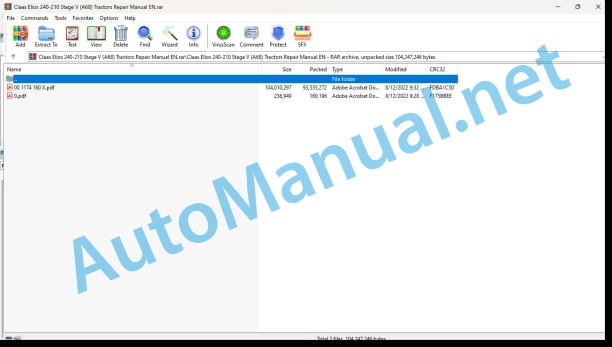
Claas Elios 240-210 Stage V (A68) Tractors Repair Manual EN
$300.00
- Model: Elios 240-210 Stage V (A68) Tractors
- Type Of Manual: Repair Manual
- Language: EN
- Format: PDF(s)
- Size: 89.4 MB
File List:
00 1174 160 X.pdf
00 1174 160 X.pdf:
ELIOS 210
Table of contents
CCN (CLAAS Component Number)
Introduction
General information
Using this repair manual
Scope of the repair manual
General repair instructions
Technical specifications
Cause of damage
Spare parts
Diesel engine
Alternator
Welding work
Drive belt/drive chains
Tapered ring assemblies
Self-locking bolts with microencapsulated glue
Threadlock
Lock collar bearing
Collet bearing
Threaded unions with cutting rings on the hydraulic hoses
Threaded unions with progressive rings on the hydraulic hoses
Threaded double flare unions on the hydraulic hoses
Flexible hydraulic pipes
Pipe routing
Advice for economical repairs
Tightening torques
Tightening torques for NF E25-030-1 2007-12-01 standard metric threads
Tightening torques for CLAAS CN 02 0225 standard hydraulic connections
Tightening torques for hydraulic threaded unions and air conditioning threaded unions with sealing cone and DIN 3865 O-ring
Tightening torques for DIN 3901 hydraulic threaded unions
Tightening torques for ISO 6149-2/ISO 11926-2 (3) adjustable hydraulic threaded unions
Tightening torques for hydraulic swivel threaded unions
Tightening torques for DIN 7643 hollow bolts
Technical specifications
Lubricants
01 Engine
0102 Complete component
Introduction
General notes
Complete engine
Special tool
Coupling the engine to the chassis
Technical specifications
Preparation for work
Disassembling the engine
Technical specifications
Preliminary operations
Disassembly
Removing the cylinder head
Assembling the engine
Assembly
Checks and inspections
0110 Engine housing
Oil sump
Technical specifications
Timing gear train housing
Technical specifications
Preparation for work
Special tool
Fitting the front bearing seal
Flywheel housing
Technical specifications
Preparation for work
Special tool
Fitting the rear bearing seal
Repairing the cylinder block
Dimensional specifications
Checks and measurements
Checking the supporting surface of the cylinder head on the cylinder block
0115 Engine unit
Crankshaft
Technical specifications
Dimensional specifications
Measuring the journals and crank pins
Crankshaft journals and crank pins – Measured values
Replacing the crankshaft front pinion
Fitting the bearing half-shells
Checking the lateral play
Connecting rod and piston assembly
Technical specifications
Dimensional specifications
Special tool
Dismantling
Checking the piston
Pairing the shaft and the piston
Piston rings
Checking the piston rings
Checking the links
Torsion check
Flexion check
Fitting the connecting rod and piston assembly – Coupling the connecting rod and piston
Fitting the piston rings
Fitting the connecting rod and piston into the cylinder
Fitting the connecting rod caps
Piston protrusion measurement
Crankshaft pulley
Technical specifications
Balancer
Technical specifications
Special tool
Flywheel
Technical specifications
0120 Cylinder head / Valves / Idler gear
Cylinder head
Technical specifications
Dimensional specifications
Sealing check
Checking the cylinder head contact surface
Checking the cylinder head contact surface (cylinder block)
Dimensional specifications
Special tool
Cleaning and checking the valves
Checking the clearance between the valve stems and the valve guide and centring the valves
Checking the valve springs
Checking and replacing the valve guides
Checking the valve guide
Replacing the valve guide
Valve guide bore
Checking and replacing the valve seats
Checking the valve withdrawal
Rocker cover
Technical specifications
Rocker arm ramp
Technical specifications
Dimensional specifications
Camshaft
Technical specifications
Dimensional specifications
Special tool
Checking the cam lift and the alignment of the shaft bearings
Replacing the rings
Fitting the valve lifters
Timing pinions
Technical specifications
Special tool
Camshaft and crankshaft timing
Adjusting the high-pressure pump and the crankshaft
0125 Injection / Fuel system
Fuel tank
Removing the fuel tank
Fuel cooler
Removing the fuel cooler
Low-pressure fuel pipes
Technical specifications
Technical specifications
Connections
Fuel pre-filter and cooler
Technical specifications
High pressure pump
Technical specifications
Special tool
Common rail
Technical specifications
Injectors
Technical specifications
0130 Lubricating oil system
Engine oil filter
Technical specifications
Oil pump
Technical specifications
Oil pressure controller
Technical specifications
Relief valve
Technical specifications
Engine oil heat exchanger
Technical specifications
Oil vapour filter (Recirculation of oil vapours)
Technical specifications
0135 Cooling system
Radiator
Removing the radiator
Drive belts
Main drive belt
Preliminary operations
Checking the tension of the main drive belt
Ventilation
Technical specifications
Water pump
Technical specifications
Thermostat
Technical specifications
0140 Exhaust system
Vertical exhaust pipe
Disassembling the vertical exhaust pipe
Turbocharger
Technical specifications
Exhaust manifold
Technical specifications
0145 Air intake
Air filter
Air filter tightening torque
Removing the air filter
Intake manifold
Technical specifications
Technical specifications
0150 Engine attachment parts
Alternator
Technical specifications
Electric starting motor
Technical specifications
Technical specifications
0155 Engine control
ECM engine control module
Technical specifications
Engine wiring harness
Technical specifications
Pre-heater plugs
Technical specifications
Preliminary operations
0165 Exhaust gas aftertreatment
Exhaust filter
Tightening torque
EGR valve
Technical specifications
Particulate filter assembly
Tightening torque
Removing the particulate filter assembly and its support
02 Gearbox / Clutch / Universal drive shaft
0202 Complete component
Tightening torques, sealing and lubrication
Application of lubricants and sealing products
Sealing products for seals
Threadlock
Assembly adhesive
Lubrication during assembly
Greasing the gearbox input shaft and the power take-off shaft
Front axle clutch housing with hydraulically-controlled clutch
Front axle clutch housing with hydraulically controlled dog clutch
24/24 transmission clutch housing with mechanically-controlled doubler
24/12 transmission clutch housing
Reduction gear housing
Brake control unit (valid for all models)
Reduction gear internal control
Separating the engine and clutch housing
Draining the transmission oil
Removing the transmission shaft
Removing the pipes
Removing the first pipe
Removing the second pipe
Removing the third pipe
Separating the engine and clutch housing
Installing the trolley underneath the tractor
Immobilising the front axle
Removing the mounting bolts
Separating the elements
Upper and lower covers
Technical specifications for the lower cover
Technical specifications for the upper cover
Preparation for work
0215 Mechanical clutch
Adjusting the clutch
11 inch clutch
Adjustment
12 inch clutch
Adjustment
Clutch for REVERSHIFT transmission with rear power take-off with mechanical clutch
Adjustment
0218 Clutch control
Reverser and clutch controls – 24/24 transmission (Mechanical reverser and doubler)
Technical specifications
Dimensional specifications
Preparation for work
Adjusting the axial play
Reverser and clutch controls – 24/12 transmission — Hydraulically controlled power take-off
Technical specifications
Dimensional specifications
Preparation for work
Special tool
Adjusting the axial play of the reverser shaft
Adjusting the axial play of the upper shaft
Clutch and hydraulic reverser controls – 24/12 and 24/24 transmission — Mechanically-controlled power take-off
Technical specifications
Dimensional specifications
Preparation for work
Special tool
FittAhe axial play of the reverser shaft
Adjusting the axial play of the upper shaft
Hydraulic control unit – “Gérotor” pump
Technical specifications
Dimensional specifications
Preparation for work
Special tool
Removing the hydraulic control unit
Fitting the hydraulic control unit
Removing the Gérotor pump
Fitting the Gérotor pump
0220 Mechanical reverser
Controls – Mechanical reverser
Technical specifications
Dismantling
Assembly
Synchronised idle gear
Technical specifications
Dismantling
Assembly
0222 Hydraulical reverser
Hydraulic reverser
Technical specifications
Preparation for work
Special tool
Dismantling
Assembly
Adjusting the release play
Wear to the packets of discs
Hydraulic reverser idle gear
Technical specifications
Dimensional specifications
Dismantling
Assembly
0228 Reverser Reverser
Adjusting the mechanical reverser
Adjustment
0230 Mechanical gearbox
Input shaft – Transmission with mechanical reverser
Technical specifications
Dimensional specifications
Preliminary operations
Assembly
Input shaft – Transmission with hydraulic reverser
Technical specifications
Dimensional specifications
Dismantling
Assembly
Primary shaft – Gears – Transmissions with mechanical reverser
Technical specifications
Dimensional specifications
Special tool
Preliminary operations
Adjusting the axial play of the primary shaft
Primary shaft – Gears – Transmission with hydraulic reverser
Technical specifications
Dimensional specifications
Adjusting the axial play of the primary shaft
Primary shaft – Ranges
Technical specifications
Dimensional specifications
Secondary shaft r Technical specifications
Special tool
Disassembly
Assembly
Secondary shaft – Gears
Technical specifications
Dimensional specifications
Special tool
Disassembly
Assembly
Adjusting the axial play of the secondary shaft – Gears
Primary shaft covers
24/24 transmission with mechanical reverser and doubler – Cross-section
24/12 transmission with hydraulic reverser and doubler – Cross-section
Mechanical doubler with mechanical reverser
Technical specifications
Dimensional specifications
0234 Powershift gearbox
Hydraulic doubler
Technical specifications
Special tool
Dismantling
Assembly
Adjusting the play
Wear to the packets of discs
0238 Gearbox control
External controls
Technical specifications
Preparation for work
Internal controls
al specifications
Dismantl Ranges
Forward/reverse gear only on the 24/24 transmission
Assembly
0240 Rear axle housing
Axle tube and final drives
Technical specifications
Special tool
Adjusting the axial play
0242 Differential
Rear axle differential
Technical specifications
Preparation for work
Dismantling
Assembly
Differential lock control
Technical specifications
Preparation for work
0248 Rear axle control
Transmission sensors
Technical specifications
Sensor/transmission applicability
Disassembly
Description
Assembly
0250 Mechanical front axle drive
Hydraulic front axle clutch
Technical specifications
Special tool
0252 Electro-hydraulical front axle drive
Front axle hydraulic clutch
Technical specifications
Special tool
0255 Gearbox cooling system
Oil cooler
0260 Universal drive shaft
Front axle transmission shaft
03 Chassis
0310 Axle
Recommendations – Servicing and repair
Shaft seals
Adjustment shims
Roller bearings
Caps and rivets
Plastic protections and caps
Cotter pins
Adhesives and sealing products
Oil drain
Cleaning
Ends of flanges and special tools
Using lubricants
0325 Front steering drive axle
Identification of the “AN” and “AR” front axle
Recommendations – Servicing and repair (4RM)
Tightening torques, lubricants and sealing products (4WD)
Steering actuator
Exploded view
Disassembling the steering actuator
Assembling the steering actuator
Epicyclic reduction unit
Exploded view
Disassembly
Assembly
Wheel hub
Exploded view
Special tool
Disassembly
Assembly
Seals – Beaport assembly
Exploded view
bling the bearing/support assembly
Assembling the bearing/support assembly
Differential housing (front axle)
Exploded view
Special tool
Disassembly
Measuring the total preload before dismantling:
Assembly
If the roller bearings have not been replaced:
If the roller bearings are new:
Alternative procedure after adjusting the clearance between the pinion/crown gear teeth
Checking the contact imprint of the differential teeth
LS-AN differential
Exploded view
Dimensional specifications
Disassembling the LS-AN differential
Assembling the LS-AN differential
LS-AR differential
Exploded view
Dimensional specifications
Disassembling the LS-AR differential
Assembling the LS-AR differential
Drive pinion
Exploded view
Special tool
Disassembling the drive pinion shaft
Measuring the initial preload before dismantling:
Assembling the drive pinion shaft
If the roller bearings have not been replaced:
If the roller bearings have been replaced:
Alternative procedure:
Front axle body
Exploded view
Special tool
Disassembling the front axle body
Assembling the front axle body
Toe-in/steering angle
Exploded view
Adjusting the toe-in
Adjusting the steering angle
Dual universal drive shaft seal/hub assembly
Cross-section
Disassembly
Assembly
Checking after assembly
Pressure check
Test methods
04 Brake
0405 Service brake
Assembly specifications
Mechanical brake
Hydraulic brake control – Tightening torques
Brake master cylinders
Slave cylinder
Exploded view
Disassembly
Assembly
Bleeding the brake circuit
Technical specifications
Preparation for work
Bleeding the brake circuit
0415 Parking brake
Parking brake
Explod view
Disassembly
Assembly
On either side of the transmission housing
Adjusting the control lever
Method to adjust the control
0425 Trailer hydraulic brake
Trailer hydraulic brake
05 Steering
0505 Steering
Steering gearbox
06 Lift device
0605 Rear power lift
Specifications
Identifying the product
Description
Main components of the linkage
Technical specifications
Main dimensions
Performance
Rear linkage settings
Rear linkage sensitivity adjustment valve
Position control lever
Draft control lever
Adjusting the force return bar
Adjusting the end of travel position sensor
Setting the shock valve pressure
Special tool
Adjustment
Assembling the reaction spring
Internal push bar
Linkage actuator and arm
Exploded view
Assembly
Rear linkage control rod linkage
Exploded view
Assembly
Rear linkage main control
Rear linkage plastic ring
Exploded view
Preliminary operations
Position control lever ring
Disassembly
Assembly
Draft control lever ring
Disassembly
Assembly
Position and draft control rod linkage
Exploded view
Disassembly
Assembly
Rear linkage spool valve
Exploded view
Preliminary operations
Disassembly
Solenoid valves
Non-return valve
Pressure balance
Rear linkage shock valve
Assembly
08 Drives
0804 Front PTO
Front power take-off
Technical specifications
0802 Rear PTO
Special tool
Rear power take-off
Tightening torques, lubricants and sealing products
Mechanical power take-off – 12/12 and 24/24 transmissions
Switches
Independent power take-off (540/540E – 540/1000)
Independent power toff (540/540E – 540/1000) and power take-off pronal to ground speed
Hydraulic power take-off – 24/12 transmission
Switches
Independent power take-off (540/540E – 540/1000)
Independent power take-off (540/540E – 540/1000) and power take-off proportional to ground speed
Cover and clutch
Exploded view
Disassembly
Assembly
Rear power take-off clutch
Wear to the packet of discs
Rear power take-off control
Exploded view
Disassembly
Only for 24/12 transmissions.
Assembly
Only for 24/12 transmission
All transmission types
Only for 24/12 transmission
All transmission types
Adjusting the rear power take-off clutch release bearing
Rear power take-off input shaft
Exploded view
Disassembly
Only without power take-off
All power take-off types
Assembly
Only without power take-off proportional to ground speed
All power take-off typear power take-off output shaft
Exploded view
Assembly
Rear power take-off brake – 24/12 transmission
Exploded view
Disassembly
Assembly
Power take-off proportional to ground speed
Exploded view – 24/12 transmission
Exploded view – except 24/12 transmission
Disassembly
Assembly
Operation of the power take-off proportional to ground speed
Rear power take-off sensors
Location
09 Hydraulic system
0920 Valves
Pressure limit valve
Exploded view
Preliminary operations
Disassembly
Cleaning
Assembly
Rear linkage spool locking
Exploded view
Preliminary operations
Disassembly
Assembly
10 Electrical / Electronic equipment
1005 Power supply
1035 Operation / Multifunction control lever
Lifting control panel
12 Cab / Operator’s platform
1210 Cab
Lever trim
Rear screen wiper
Cab mount
Preparation for work
Front cab m mounting
Rear cab mount mounting
Complete cab
Special tool
1240 Air condition
Air conditioning compressor
80 Various components / Machine body
8025 Panellings / Hoods
Engine bonnet
Removing the engine bonnet
Bonnet side panels
John Deere Repair Technical Manual PDF
John Deere Application List Component Technical Manual CTM106819 24AUG20
John Deere Repair Technical Manual PDF
John Deere Repair Technical Manual PDF
John Deere Transmission Control Unit Component Technical Manual CTM157 15JUL05
John Deere Repair Technical Manual PDF
John Deere POWERTECH E 4.5 and 6.8 L Diesel Engines TECHNICAL MANUAL 25JAN08
John Deere Repair Technical Manual PDF
John Deere Repair Technical Manual PDF
John Deere Repair Technical Manual PDF
John Deere Parts Catalog PDF
John Deere Harvesters 8500 and 8700 Parts Catalog CPCQ24910 Spanish
John Deere Repair Technical Manual PDF
John Deere 18-Speed PST Repair Manual Component Technical Manual CTM168 10DEC07
John Deere Repair Technical Manual PDF
John Deere 16, 18, 20 and 24HP Onan Engines Component Technical Manual CTM2 (19APR90)


