Claas Jaguar 900-830 (493) Forage Harvesters Operator Manual FR
$50.00
- Model: Jaguar 900-830 (493) Forage Harvesters
- Type Of Manual: Operator Manual
- Language: FR
- Format: PDF(s)
- Size: 51.5 MB
File List:
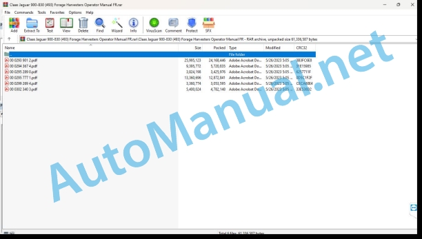
00 0293 901 2.pdf
00 0294 367 4.pdf
00 0295 289 0.pdf
00 0295 777 1.pdf
00 0299 269 4.pdf
00 0302 340 3.pdf
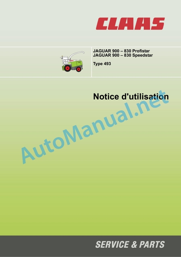
00 0293 901 2.pdf:
Contents
1 Introduction
1.1 General advice
1.1.1 Use of the instructions
1.1.2 Validity of the notice
1.1.3 Technical information
1.1.4 Driving on the road
1.1.5 Advice regarding electronic engine management
1.1.6 Information regarding the metal detector
1.1.7 Notes on the stone detector
1.2 Nameplates and identification numbers
1.2.1 Spare parts and technical questions
1.2.2 Machine nameplate
1.2.3 Crusher block nameplate
1.2.4 Mercedes-Benz OM 502 LA engine nameplate
1.2.5 Mercedes-Benz OM 460 LA engine nameplate
1.2.6 Engine rear axle rating plate
2 Overview
2.1 JAGUAR 900-830 Profistar / Speedstar
2.1.1 Overview of the machine from the front and left
2.1.2 Overview of the rear and right side of the machine
2.1.3 Table of working groups
3 Safety Tips
3.1 General advice
3.1.1 Important
3.1.2 Conformity of use
3.1.3 Safety and accident prevention instructions
3.1.4 Safety and accident prevention instructions for the forage harvester
3.1.5 Before commissioning – General
3.1.6 Additional weights
3.1.7 Transport of people
3.1.8 General rule of conduct
3.1.9 Driving the forage harvester
3.1.10 Driving on a slope
3.1.11 Exit the machine
3.1.12 Front implements and trailers
3.1.13 Chopping device of the forage harvester
3.1.14 Air conditioning
3.1.15 Adjustment and maintenance work
3.1.16 Pressure accumulator
3.1.17 Antifreeze
3.1.18 First aid measures
3.1.19 Brake blocks
3.1.20 Fire extinguisher
3.1.21 Battery cut-off switch
3.1.22 Hydraulic fluid poses a risk of injury
3.1.23 Instruction for checking the air brake system
3.1.24 Load the machine and secure it
3.2 Safety information
3.2.1 Marking of warnings and dangers
3.3 Warning pictograms
3.3.1 General information on warning pictograms
3.3.2 Driving position
3.3.3 Power supply
3.3.4 Machine components
3.3.5 Hydraulic system
3.3.6 Motor
3.3.7 Ejection
4 Technical characteristics
4.1 JAGUAR 900 / 890 / 870 / 850 / 830 Speedstar – TYPE 493
4.1.1 General advice
4.1.2 Dimensions
4.1.3 Weight
4.1.4 Driving position
4.1.5 Electricity
4.1.6 Power supply
4.1.7 Chassis
4.1.8 Motor
4.1.9 Chopping
4.1.10 Eject
4.1.11 Central lubrication system
4.2 JAGUAR 900 / 890 / 870 / 850 / 830 Profistar – type 493
4.2.1 General advice
4.2.2 Dimensions
4.2.3 Weight
4.2.4 Driving position
4.2.5 Electricity
4.2.6 Power supply
4.2.7 Chassis
4.2.8 Motor
4.2.9 Chopping
4.2.10 Ejection
4.2.11 Central lubrication system
5 Before first commissioning
5.1 General advice
5.1.1 Checklist for initial commissioning
5.1.2 Load the machine and secure it
5.2 Driving position
5.2.1 Mounting the high beam headlights
5.2.2 Adjusting the long-range headlights
5.2.3 Mounting the work light
5.2.4 Fit the exterior mirrors
5.2.5 Installing the blind spot mirror (auxiliary equipment)
5.2.6 Mount the rotating beacon
5.2.7 Connect the side window windshield washer device
5.2.8 Install the fan/air conditioning fuse
5.3 Power supply
5.3.1 Remove the security screw
5.4 Machine components
5.4.1 Remove the machine roof cover plate
5.4.2 Install the hitch yoke (optional equipment).
5.5 Ejection
5.5.1 Switch the ejector elbow from the transport position to the working position
5.6 Central lubrication system
5.6.1 Fill the central lubrication lubricant tank
6 Before each commissioning
6.1 General advice
6.1.1 Daily start-up checklist
6.2 Driving position
6.2.1 Adjusting the blind spot mirror (auxiliary equipment)
6.3 Axle frame
6.3.1 Overview of the steering axle
6.3.2 Adjusting the steering axle track (000 769 250 0)
6.4 Machine components
6.4.1 Additional weights
6.4.2 Options from other manufacturers
6.4.3 Additives for silage
7 Overview of control elements
7.1 Driving position
7.1.1 Overview of the driving position
7.1.2 Control console
7.1.3 Overview on the monitor
7.1.4 Overview of the cabin ceiling
7.1.5 Driving informant
7.1.6 Multifunction handle
7.1.7 Lever of advancement
7.1.8 Adjusting the steering column
7.1.9 Multifunction switch
7.1.10 Mechanically cushioned driver’s seat (optional equipment)
7.1.11 Driver’s pneumatic seat (optional equipment)
7.1.12 Automatic air conditioning
7.1.13 Activate automatic air conditioning
7.1.14 Automatic adjustment of cabin temperature
7.1.15 Manual adjustment of cabin temperature
7.1.16 Adjusting the air conditioning air flow
7.1.17 Remove fog from the cabin windows
7.1.18 Display of the outside temperature
7.1.19 Convert temperature display to ˚Fahrenheit
7.1.20 Open the cabin roof
7.1.21 Close the cabin roof
7.1.2 indshield washer system reservoir
7.1.23 Side window washer system reservoir
7.1.24 Female connector of the driving position
7.1.25 Control elements of the driving position
7.1.26 Access scale
7.1.27 Open the power station
7.1.28 Close the power plant
7.1.29 Power plant
7.1.30 Adjusting the control resistance of the forward lever
7.2 Axle frame
7.2.1 CLAAS 4-trac system (optional equipment)
7.3 Machine components
7.3.1 Toolbox
7.3.2 Work and high beam headlight
7.3.3 12 volt female socket
7.4 Engine
7.4.1 Ignition lock
7.4.2 Diesel engine speed
7.4.3 Activate the diesel engine
7.4.4 Disable diesel engine
7.5 Braking system
7.5.1 Service brake
7.5.2 Parking brake
8 Assembly/disassembly of the front implement and trailer
8.1 Front tool
8.1.1 Adjusting the machine hydraulics on the front attachment
8.1.2 Connect the central lubrication system to the front tool
8.2 Hitch
8.2.1 Unhitching the trailer
8.2.2 Hitch the trailer
8.2.3 Compressed air brake system for trailer (optional equipment)
8.2.4 Uncoupling the trailer with air brake (auxiliary equipment)
9 Road driving and transport
9.1 General advice
9.1.1 Preparing for driving on the road
9.1.2 Preparing for driving in the field
9.1.3 Management
9.1.4 Park the machine
9.1.5 Maneuvers with the machine
9.1.6 Driving characteristics
9.1.7 Towing the machine
9.2 Driving position
9.2.1 Adjusting the mechanically cushioned driver’s seat (optional equipment)
9.2.2 Adjusting the pneumatic driver’s seat (optional equipment)
9.2.3 Control a speed
9.3 Axle frame
9.3.1 CLAAS 4-trac system (optional equipment)
9.3.2 Deactivating the CLAAS 4-trac system (optional equipment)
9.4 Hydraulics
9.4.1 Vibration damping
9.4.2 Calibration of the vibration damper
9.4.3 Switching on the vibration damper
9.5 Engine
9.5.1 Adjusting the speed of the diesel engine when driving on the road (electrohydraulic)
9.5.2 Diesel engine speed adjustment during operation (electro-hydraulic)
9.6 Braking system
9.6.1 Check the brake pressure switch
9.6.2 Activate the parking brake
9.6.3 Release the parking brake
9.6.4 Brake the machine using the multifunction lever
9.6.5 Braking the machine with the foot brake
9.6.6 Air brake (auxiliary equipment) anti-freeze fluid pump
9.6.7 Activate the air brake anti-freeze pump (auxiliary equipment)
9.6.8 Disable air brake anti-freeze fluid pump (auxiliary equipment)
10 Setting for work
10.1 General warning information
10.2 Power supply
10.2.1 Mounting the bottom plate
10.3 Chopping
10.3.1 Chopping knife
10.3.2 Counterblade
10.3.3 Half knife (grass)
10.3.4 Fitting the knife holder guard (additional equipment)
10.3.5 Reduce the number of knives
10.3.6 Installing the micro-friction system knives (additional equipment)
10.3.7 Crusher bottom plate (optional equipment)
10.3.8 Manually preset hash length
10.3.9 Adjusting the crusher bottom plate
10.4 Corn cracker
10.4.1 Decommission the corn cracker (optional equipment)
10.4.2 Installation of the grass channel (optional equipment)
10.4.3 Mounting the corn cracker (optional equipment)
11 CIS Commands
11.1 General advice
11.1.1 Functions and displays
11.1.2 Before first commissioning
11.2 Driving position
11.2.1 Overview of the status display A
11.2.2 Overview on control screen B
11.2.3 Overview of key area C
11.2.4 Calling functions / operating data
11.2.5 Edit values
11.2.6 Displaying and setting the time
11.2.7 Display of total working hours (CIS with on-board computer)
11.2.8 Display/reset of daily total working hours (CIS with on-board computer)
11.2.9 Display of operating hours
11.2.10 Display/reset of daily area (CIS with on-board computer)
11.2.11 Surface capacity display (CIS with on-board computer)
11.2.12 Total area display (CIS with on-board computer)
11.2.13 Display of next expected service interval / elapsed time (CIS with on-board computer)
11.2.14 Confirmation of completion of maintenance (CIS with on-board computer)
11.2.15 Define the number of pulses/100 m
11.2.16 Define the pulse/100 m by a calibration path
11.2.17 Enter pulses/100 m directly
11.2.18 Unit setting
11.2.19 Saving the working position (CIS with on-board computer)
11.2.20 Adjusting the working width (CIS with on-board computer)
11.2.21 Adjusting the division of the front tool (CIS with on-board computer)
11.2.22 Adjusting the partial width of the front implement (CIS with on-board computer)
11.2.23 Learn the advance lever
11.2.24 Setting the driving strategy
11.3 Power supply
11.3.1 Adjusting the sensitivity of the metal detector
11.3.2 Monitoring the pressure in the cylinders during ground support adjustment
11.3.3 Monitoring the current height of the front attachment / preselection of cutting height
11.3.4 Calibrate the Contour stops
11.3.5 Check the front tool height potentiometer
11.3.6 Adjusting the front tool height potentiometer
11.3.7 Stop the power supply
11.4 Axle frame
11.4.1 Calibrate the autopilot
11.5 Machine components
11.5.1 Adjust the dosage of the silage additive (from machine No. …)
11.6 Engine
11.6.1 Motor load display
11.6.2 Engine speed display
11.6.3 Setting the working regime
11.6.4 Fuel consumption display (auxiliary equipment)
11.7 Chopping
11.7.1 Adjusting the cutting length of the grinder
11.7.2 Setting the number of knives
11.7.3 Automatic sharpening and counter-knife
11.7.4 Setting the number of sharpening cycles
11.7.5 Sharpening reminder function
11.7.6 Setting the time interval until the next sharpening
11.7.7 Checking the time until the next sharpening
11.7.8 Activation of automatic sharpening
11.7.9 Monitoring of the automatic sharpening system
11.7.10 Reset total sharpening cycles
11.7.11 Adjusting the distance between counter-knives
11.7.12 Activation of the counter-knife automation
11.7.13 Monitoring of the counter-blade automation
11.7.14 Reset remaining state of knives
11.7.15 Adjust the basic setting of the counter knife
11.7.16 Check the automatic sharpening and counter-knife sensors
11.8 Corn cracker
11.8.1 Corn-cracker roller gap display (optional equipment)
11.8.2 Program the corn-cracker roll spacing (optional equipment).
11.9 Ejection
11.9.1 Calibration of the ejection elbow end stops
12.1 General warning information
12.2 Driving position
12.2.1 Cutting height control
12.2.2 Saving the cutting height
12.2.3 Memorization of the support pressure
12.2.4 Activate cutting height control
12.2.5 Disable cutting height control
12.3 Power supply
12.3.1 Activate the power supply
12.3.2 Metal detector, metal discovery
12.3.3 Activate the stone detector (auxiliary equipment)
12.3.4 Disable stone detector (auxiliary equipment)
12.3.5 Inversion
12.3.6 Enable inversion
12.4 Axle frame
12.4.1 CLAAS Autopilot (auxiliary equipment)
12.4.2 Activate CLAAS autopilot (auxiliary equipment)
12.4.3 Deactivate CLAAS autopilot (auxiliary equipment)
12.4.4 Adjusting the middle of the CLAAS autopilot (auxiliary equipment)
12.4.5 Adjusting the laser driver (additional equipment)
12.5 Machine components
12.5.1 Silage system
12.5.2 Activate silage additive device
12.5.3 Switching off the silage additive system
12.5.4 Silage hopper
12.5.5 Dosing nozzle of the silage additive device
12.5.6 Select the dosing nozzle of the silage additive device
12.5.7 CLAAS ACTISILER silage additive device (additional equipment) Overview of operating elements
12.5.8 Connecting the CLAAS ACTISILER silage additive device (additional equipment)
12.5.9 Use of the CLAAS ACTISILER silage additive device (additional equipment)
12.5.10 CLAAS ACTISILER silage additive device (additional equipment) set calibration value
12.5.11 Disconnect the CLAAS ACTISILER silage additive device (additional equipment)
12.5.12 Filling the CLAAS ACTISILER silage additive device (additional equipment)
12.5.13 Draining the CLAAS ACTISILER silage additive device (additional equipment)
12.6 Engine
12.6.1 Filling the tank
12.7 Chopping
12.7.1 Chopping bodies
12.7.2 Disable hashing bodies
12.7.3 Sharpening chopping blades
12.7.4 Manual adjustment of the sharpening stone
12.7.5 Special tool for sharpening stone
12.8 Corn cracker
12.8.1 Corn cracker (optional equipment)
12.8.2 Electrical adjustment of the gap between the corn cracker rollers (optional equipment)
12.8.3 Mechanical adjustment of the gap between the corn cracker rollers (optional equipment)
12.9 Ejection
12.9.1 Ejection accelerator
12.9.2 Ejection elbow
12.9.3 Raising the ejector elbow
12.9.4 Pivoting of the ejector elbow
12.9.5 Lowering the ejector elbow
12.9.6 Activate automatic swivel of the ejector elbow (auxiliary equipment)
12.9.7 Memorization of the automatic pivoting position of the ejector elbow (auxiliary equipment)
13 Incidents and remedy
13.1 General warning information
13.2 General advice
13.2.1 Hydraulic system
13.2.2 Electrical system
13.2.3 Air conditioning
13.2.4 Protective devices
13.2.5 Spare parts
13.2.6 Unbalance
13.2.7 Welding work on the forage harvester
13.2.8 Turn off the machine
13.2.9 Lifting the machine using jacks
13.3 Driving position
13.3.1 Automatic air conditioning error code table
13.3.2 Air conditioning incidents and remedies
13.3.3 CIS alarm types
13.3.4 CIS error code table
13.4 Axle frame
13.4.1 Incidents and solutions for the CLAAS autopilot
13.4.2 Switch off the control rod locking hydraulic cylinder
13.5 Outing / Training
13.5.1 Failure of the reversal process
13.6 Machine components
13.6.1 Incident and solutions ACTISILER CLAAS
13.7 Engine
13.7.1 The coolant temperature display lights up
13.7.2 Diesel engine failure
13.8 Corn cracker
13.8.1 Manual adjustment of the Corn-cracker (optional equipment) with electrical adjustment of the roller gap
13.9 Central lubrication system
13.9.1 Central lubrication system incident and remedy
14 Maintenance
14.1 General warning information
14.2 General advice
14.2.1 Clean the engine compartment and hazardous areas
14.2.2 Belts
14.2.3 Drives
14.2.4 Bolting
14.2.5 Lubrication
14.2.6 Brakes
14.2.7 Wheels / tires
14.2.8 Hydraulic system
14.2.9 Electrical system
14.2.10 Air conditioning
14.2.11 Coolant
14.2.12 Protective devices
14.2.13 Spare parts
14.2.14 Unbalance
14.2.15 Turn off the machine
14.2.16 Lifting the machine using jacks
14.2.17 Tips for winterizing the forage harvester
14.3 Maintenance table
14.3.1 Maintenance frequencies
14.4 Lubricant table
14.4.1 Lubricants
14.5 Driving position
14.5.1 Clean/replace the cabin air filter
14.5.2 Cleaning the groups in the cabin roof
14.5.3 Clean the air conditioning condenser
14.5.4 Checking the refrigerant level in the air conditioning
14.5.5 Commissioning the air conditioning
14.5.6 Checking the fire extinguisher
14.6 Electricity
14.6.1 Checking the battery acidity level
14.7 Power supply
14.7.1 Switching the power supply
14.7.2 Dismantle the power supply unit
14.7.3 Mount the power supply unit
14.7.4 Adjust the transport roller under the scraper
14.7.5 Adjusting the feed drum brake
14.7.6 Adjusting the feed drum springs
14.7.7 Check the upper roller housing oil level
14.7.8 Drain the oil from the upper roller housing
14.7.9 Fill the upper roller housing with oil
14.7.10 Check the oil level of the feeder gearbox
14.7.11 Change the oil from the power unit gearbox
14.7.12 Filling the feeder gearbox with oil
14.8 Workouts
14.8.1 Loosen the chopping unit belt
14.8.2 Remove the chopper unit belt
14.8.3 Remove the chopper unit belt
14.8.4 Adjust the chopping unit belt
14.8.5 Remove the fan drive belt
14.8.6 Install the fan drive belt
14.8.7 Adjusting the fan drive belt
14.8.8 Remove the corn cracker belt (optional equipment)
14.8.9 Install the corn cracker belt (optional equipment)
14.8.10 Adjust the corn cracker belt (optional equipment)
14.8.11 Remove the front implement drive belt
14.8.12 Install the front implement drive belt
14.8.13 Remove the hydrostatic motor belt from the power unit
14.8.14 Install the power unit hydrostatic motor belt
14.8.15 Adjusting the feeder hydraulic motor belt
14.9 Axle frame
14.9.1 Wheel nuts, check tightening torque
14.9.2 Drive axle gearbox, clean surrounding area
14.9.3 Checking the oil level in the drive axle gearbox
14.9.4 Change the oil from the drive axle gearbox
14.9.5 Filling the drive axle gearbox
14.9.6 Check the gearbox oil level
14.9.7 Drain the gearbox oil
14.9.8 Filling the gearbox with oil
14.9.9 Engine rear axle (optional equipment) check the differential oil level
14.9.10 Engine rear axle (optional equipment) Drain the oil from the differential of the
14.9.11 Engine rear axle (optional equipment) Filling the differential
14.9.12 Engine rear axle (optional equipment) check the gearbox oil level
14.9.13 Engine rear axle (optional equipment) Drain the gearbox oil
14.9.14 Engine rear axle (optional equipment) Filling the gearbox oil
14.9.15 Engine rear axle (optional equipment) check the gearbox oil level
14.9.16 Engine rear axle (optional equipment) Drain the oil from the drive housing
14.9.17 Engine rear axle (optional equipment) filling drive housing oil
14.10 Machine components
14.10.1 Side hatch
14.10.2 Flush the silage additive device
14.10.3 Clean the nozzle of the silage additive device
14.10.4 Cleaning the silage additive device filter
14.10.5 Winterizing the silage system
14.10.6 Rinse the CLAAS ACTISILER silage additive device (additional equipment)
14.10.7 Maintenance of the CLAAS ACTISILER silage additive device (additional equipment)
14.10.8 Compressed air cleaning installation
14.10.9 Check the drain valve of the compressed air cleaning device
14.10.10 Check the reservoir of the compressed air cleaning device
14.10.11 Check the pressure regulator of the compressed air cleaning device
14.10.12 Check the safety valve of the compressed air cleaning device
14.11 Hydraulics
14.11.1 Discharging the pressure accumulator
14.11.2 Check the oil level in the hydraulic tank
14.11.3 Drain the hydraulic oil from the tank
14.11.4 Filling the hydraulic tank with oil
14.11.5 Replacing the return filter to the hydraulic tank
14.11.6 Changing the hydraulic motor oil
14.11.7 Replacing the hydraulic pump oil filter
14.11.8 Surroundings of the pump and hydraulic motor
14.12 Motor
14.12.1 Overview of the Mercedes-Benz OM 502 LA engine
14.12.2 Overview of the Mercedes-Benz OM 460 LA engine
14.12.3 Overview of the cooling elements
14.12.4 Clean the area surrounding the diesel engine
14.12.5 Checking the diesel engine oil level
14.12.6 Diesel engine, oil change
14.12.7 Changing the diesel engine oil filter
14.12.8 Filling the diesel engine with oil
14.12.9 Replacing the diesel engine purge filter
14.12.10 Check the oil level in the distributor housing
14.12.11 Drain the distributor box
14.12.12 Filling the distributor housing with oil
14.12.13 Check the fan housing oil level
14.12.14 Drain the oil from the fan housing
14.12.15 Filling the fan housing with oil
14.12.16 Drain fuel from fuel tank
14.12.17 Clean the fuel filter element
14.12.18 Replace the fuel filter
14.12.19 Fuel pre-filter replacement
14.12.20 Bleed the air from the fuel system
14.12.21 Drain the coolant from the cooler
14.12.22 Check the coolant level of the water cooler
14.12.23 Filling the cooler with coolant
14.12.24 Identify coolant quality
14.12.25 Coolant mixing ratio
14.12.26 Replace the coolant
14.12.27 Cleaning the cooling element
14.12.28 Clean the air filter suction strainer
14.12.29 Tighten the air suction hose clamps
14.12.30 Diesel engine, clean / replace air filter
14.12.31 Changing the diesel engine air filter safety cartridge
14.13 Chopping
14.13.1 Block the chopping knife drum
14.13.2 Adjusting the knives
14.13.3 Replacing the chopping knives
14.13.4 Tighten the chopping knife screws
14.13.5 Replace the counterblade
14.14 Corn cracker
14.14.1 Checking the gap between the corncracker rollers (optional equipment)
14.14.2 Adjusting the corn cracker roller gap (optional equipment)
14.14.3 Bleed the corn cracker hydraulic system (optional equipment)
14.14.4 Cleaning the corn cracker (optional equipment)
14.14.5 Checking the corn cracker rollers (optional equipment)
14.14.6 Manually grease the corn cracker (optional equipment)
14.15 Ejection
14.15.1 Clean the ejector elbow
14.15.2 Clean the ejection compartment
14.15.3 Replace the throttle ejection blades
14.15.4 Adjusting the throttle blade wheel
14.15.5 Ejection elbow wear plates
14.15.6 Adjusting the ejector elbow safety
14.16 Braking system
14.16.1 Clean around the brake
14.16.2 Check / top up the brake fluid
14.16.3 Filling the reservoir of the antifreeze pump of the air brake device (auxiliary equipment)
14.16.4 Check the bleed valve of the air brake device (auxiliary equipment)
14.17 Central lubrication system
14.17.1 Central lubrication system
14.17.2 Central lubrication device pressure switch
14.17.3 Fill the central lubrication system reservoir
14.17.4 Manually activate central lubrication
14.17.5 Manual lubrication using the central lubrication device
15 Lubrication plan
15.1 Lubrication points
15.1.1 General safety advice
15.1.2 Fats
15.1.3 Lubrication intervals
15.1.4 Lubrication points – 10 o’clock left side
15.1.5 Lubrication points – 10 o’clock right side
15.1.6 Lubrication points – 50 h left side
15.1.7 Lubrication points – 50 h right side
15.1.8 Lubrication points – 100 h left side
15.1.9 Lubrication points – 100 h right side
15.1.10 Lubrication points – 250 h left side
15.1.11 Lubrication points – 500 h left side
15.1.12 Lubrication points – 500 h right side
Alphabetical index
00 0294 367 4.pdf:
JAGUAR 900 – 830
Contents
About this user manual
General informations
Validity of the notice
CIS commands
General informations
Functions and displays
Before first commissioning
Cabin / Driving position
Overview – Status displays A (up to machine no. …)
Overview – Screen area B (to machine no. …)
Overview – Status displays A (from machine no. …)
Overview – Screen area B (from machine no. …)
Overview of the C key area
Calling functions / operatin Change values
Time display and setting
Display of total working hoursth on-board computer)
Display/reset of daily total working hours (CIS with on-board computer)
Display of service hours
Display/reset of daily area (CIS with on-board computer)
Surface capacity display (CIS with on-board computer)
Total area display (CIS with on-board computer)
Display of next expected service interval / elapsed time (CIS with on-board computer)
Confirmation of completion of maintenance (CIS with on-board computer)
Set number of pulses/100 m
Set pulse/100m by one calibration path
Enter pulses/100m directly
Unit setting
Saving the working position (CIS with on-board computer)
Working width adjustment (CIS with on-board computer)
Front implement division adjustment (CIS with on-board computer)
Adjusting the partial width of the front implement (CIS with on-board computer)
Learn the advancement lever
Setting the driving strategy
Power group
Monitoring the pressure in the cylinders during ground support adjustment
Monitoring the current height of the front attachment / cutting height preselection
Calibrate the Contour stops
Check the front tool height potentiometer
Adjusting the front tool height potentiometer
Stop the power supply
Learn Autopilot
Assembly parts / Bodywork
Adjust the dosage of the silage additive (from machine no. …)
Motor load display
Engine speed display
Adjustment of the working regime
Fuel consumption display (auxiliary equipment)
Automatic sharpening and counter-blade
Setting the number of sharpening cycles
Sharpening reminder function
Setting the time interval until the next sharpening
Time control until next sharpening
Activation of automatic sharpening
Monitoring of the sharpening automation
Reset total sharpening cycles
Adjusting the counterblade gap
Activation of the counter-blade automation
Monitoring of the automatic counter-blade
Reset remaining state of knives
Adjust the basic setting of the bedknife
Check the automatic sharpening and counter-blade sensors
Corn cracker
Corn-cracker roll gap display (optional equipment)
Program corn-cracker roll spacing (optional equipment)
Calibration of the ejection elbow end stops
Incidents and remedies
CIS alarm types
CIS Error Code Table
00 0295 289 0.pdf:
Contents
1 Introduction
1.1 General advice
1.1.1 Use of the instructions
1.1.2 Validity of the notice
2 Safety Tips
2.1 Observe
2.1.1 Important
2.1.2 Marking of warnings and dangers
3 pieces supplied
3.1 Quantimeter with CLAAS CEBIS MOBILE
3.1.1 Retrofit kit 009 101 592 7 / 009 101 592 8
4 Assembly
4.1 Installation of the CEBIS MOBILE CLAAS efficiency measurement device
4.1.1 Modification of the central electrical system
4.1.2 Route the cable set
4.1.3 Installation of the CEBIS MOBILE control element
4.1.4 Remove the fuel casing
4.1.5 Installation of the angle sensor
4.1.6 Fitting the feed cover
4.1.7 Connect the angle sensor
4.2 Installation of the yield map (additional equipment) CEBIS MOBILE
4.2.1 Installation of the GPS antenna (additional equipment)
5 Before first commissioning
5.1 General advice
5.1.1 Checklist for initial commissioning
6 Before each commissioning
6.1 CEBIS MOBILE CLAAS
6.1.1 Install the smart card
7 Use CEBIS MOBILE CLAAS
7.1 General advice
7.1.1 CEBIS MOBILE CLAAS
7.2 Control element and display
7.2.1 Control element
7.2.2 Forage harvester menu with movement indicator
7.2.3 Forage harvester menu with work indicator
7.2.4 Construction sites menu
7.3 Menu structure
7.3.1 Select menu
7.3.2 Overview of the Forage Harvester Menu
7.3.3 Travel indicator / work indicator menu
7.3.4 Counterweighing menu
7.3.5 Calibrate menu
7.3.6 Counter Menu
7.3.7 Site overview menu
7.3.8 Construction sites menu
7.3.9 GPS menu
7.3.10 Settings menu
7.4 Calibration
7.4.1 Determine and set the calibration dimension
7.4.2 Adjust the response threshold
7.4.3 Learn zero gap.
Alphabetical index
00 0295 777 1.pdf:
Contents
1 Introduction
1.1 General advice
1.1.1 Use of the instructions
1.1.2 Validity of the notice
1.1.3 Technical information
1.2 Nameplates and identification numbers
1.2.1 Spare parts and technical questions
1.2.2 Nameplate
2 Safety Tips
2.1 General advice
2.1.1 Important
2.1.2 Conformity of use
2.2 Safety information
2.2.1 Marking of warnings and dangers
2.3 Warning pictograms
2.3.1 General advice regarding warning pictograms
2.3.2 Adapter
3 pieces supplied
3.1 LEXION front tool adapter
3.1.1 Retrofit clearance
4 Assembly
4.1 Prepare the installation
4.1.1 Turn off the machine
4.1.2 Check the parts provided
4.2 Assembly of machine equipment
4.2.1 Installing the hydraulic system (JAGUAR types 492/493 only)
4.2.2 Installation of the electrical system (only JAGUAR types 492/493)
4.2.3 Installation of the electrical system (JAGUAR type 494 only)
4.2.4 Shorten the PTO adapter (only JAGUAR type 493/494)
4.2.5 Preassemble the multicoupling
4.2.6 Install the reel peripheral speed cable set (cutting deck only, only for types 492/493)
4.2.7 Prepare a test operation and carry it out
5 Technical characteristics
5.1 JAGUAR – LEXION front tool adapter – TYPES 492 / 493 / 494
5.1.1 Dimensions
5.1.2 Weight
5.1.3 Acceptable front-end tools
6 Before first commissioning
6.1 General advice
6.1.1 General warnings Before initial commissioning
6.1.2 Checklist for initial commissioning
7 Before each commissioning
7.1 General advice
7.1.1 General warnings Before each commissioning
7.1.2 Commissioning checklist
8 Mount/dismount the front tool
8.1 General advice
8.1.1 General warnings place/remove the front tool
8.2 Mounting the adapter
8.2.1 Connect the cable set (JAGUAR type 494 only)
8.2.2 Remove the quick coupling (JAGUAR types 493/494 only)
8.2.3 Mounting the adapter
8.3 Install the front tool
8.3.1 Install CONSPEED
8.3.2 Install the cutting deck (folding)
8.4 Remove the adapter
8.4.1 Disconnect the cable set (JAGUAR type 494 only)
8.4.2 Remove the adapter
8.4.3 Install the quick coupling (JAGUAR types 493/494 only)
9.1 General advice
9.1.1 General work warning advice
9.2 Cabin / driving position
9.2.1 Control elements
10 Incidents and remedy
10.1 General advice
10.1.1 General warning tips Fault and solution
10.2 Attached parts / machine casing
10.2.1 Setting the lock
11 Maintenance
11.1 General advice
11.1.1 General warning advice Maintenance
11.2 General maintenance information
11.2.1 Fixing material
11.2.2 Post-harvest maintenance work
11.2.3 Tightening torque for metric adjustment thread
11.2.4 Tightening torques for fine metric threads
11.2.5 Tightening torques for hydraulic connections with cutting ring DIN 3861
11.2.6 Tightening torques for hydraulic connections and air conditioning connections with bicone ring and O-ring DIN 3865
11.3 Maintenance table
11.3.1 Maintenance frequencies
11.4 Lubricant table
11.4.1 Lubricants
11.5 Gearbox / Clutch
11.5.1 Check transmission gearbox oil level
11.5.2 Pour oil into the transmission gearbox
11.5.3 Change transmission gearbox oil
11.5.4 Check output gearbox oil level
11.5.5 Pour oil into the output gearbox
11.5.6 Change output gearbox oil
12 Lubrication plan
12.1 General advice
12.1.1 General warning tips lubrication scheme
12.2 Lubrication points
12.2.1 Lubrication intervals
12.2.2 Lubrication points – 100 h
Alphabetical index
John Deere Repair Technical Manual PDF
John Deere DF Series 150 and 250 Transmissions (ANALOG) Component Technical Manual CTM147 05JUN98
John Deere Repair Technical Manual PDF
John Deere Repair Technical Manual PDF
John Deere Repair Technical Manual PDF
John Deere Repair Technical Manual PDF
John Deere 16, 18, 20 and 24HP Onan Engines Component Technical Manual CTM2 (19APR90)
John Deere Parts Catalog PDF
John Deere Tractors 7500 Parts Catalog CPCQ26568 30 Jan 02 Portuguese
John Deere Repair Technical Manual PDF
John Deere Repair Technical Manual PDF
John Deere Parts Catalog PDF
John Deere Tractors 6300, 6500, and 6600 Parts Catalog CQ26564 (29SET05) Portuguese

