Komatsu PC8000-6 Diesel Hydraulic Mining Shovel Shop Manual 12071-upD-GB-01
$40.00
- Type Of Manual: Shop Manual
- Manual ID: 12071-upD-GB-01
- Format: PDF
- Size: 103.0MB
- Number of Pages: 1802
Category: Komatsu Shop Manual PDF
-
Model List:
- PC8000-6 Diesel Hydraulic Mining Shovel
- 1. SHOP MANUAL COVER
- 2. FOREWORD SAFETY
- 2.1. FOREWORD
- 2.1.1. BEFORE READING THIS MANUAL
- 2.1.2. DIRECTIONS OF THE MACHINE
- 2.1.3. SPECIFICATION AND SERIAL PLATE
- 2.1.4. DIVISION OF THE BINDER
- 2.1.5. DESIGNATED USE OF THE SHOVEL
- 2.1.6. DELIVERY OF THE SHOVEL
- 2.1.7. EXPLANATION OF ABBREVIATIONS
- 2.1.8. CONTENTS
- 2.2. SAFETY
- 2.2.1. SAFETY INFORMATION
- 2.2.2. OVERVIEW
- 2.2.3. SOUND PRESSURE LEVEL IN THE OPERATORS CAB.
- 2.2.4. GENERAL PRECAUTIONS COMMON TO OPERATION ON THE EXCAVATOR
- 2.2.5. PRECAUTION FOR MAINTENANCE
- 2.2.6. ADDITIONAL SAFETY INFORMATION FOR TROUBLESHOOTING AND ADJUSTMENTS
- 2.2.7. SPECIAL SAFETY EQUIPMENT
- 2.2.8. SAFETY WARNING SIGNS
- 3. Specification
- 4. Structure Function
- 4.1. Introduction
- 4.1.1. Contents of the binder
- 4.1.2. Foreword
- 4.1.3. Recommendations for environmentally friendly operation and maintenance of hydraulic mining shovels
- 4.1.4. Explanation of abbreviations
- 4.1.5. Diagrams and illustrations in this manual
- 4.2. Specifications
- 4.2.1. Lifting Gears
- 4.2.2. Safety hints for sling accessory
- 4.2.3. Standard Tightening Torque Chart
- 4.2.4. Conversion Table
- 4.2.5. Blind plugs
- 4.2.6. Classification of threads to the nominal width
- 4.2.7. Plugs and fittings according to ISO 84341 / DIN 2353
- 4.2.8. Sensor Limit Values
- 4.3. Main assembly groups
- 4.3.1. General layout
- 4.3.2. Superstructure
- 4.3.3. Machine house
- 4.3.4. Hydraulic oil tank
- 4.3.5. Hydraulic oil cooler
- 4.3.6. Fuel tank
- 4.3.7. Cab support
- 4.3.8. Operators cab
- 4.3.9. Control blocks
- 4.3.10. Swing machinery
- 4.3.11. Undercarriage
- 4.3.12. Attachments
- 4.4. Drive
- 4.4.1. Prime drive assembly
- 4.4.2. Engine mounts
- 4.4.3. Drive shaft
- 4.4.4. Flexible coupling
- 4.4.5. Fan drive and radiator assembly
- 4.4.6. Pump distributor gearbox (PTO)
- 4.4.7. Air filter
- 4.5. Hydraulic oil tank
- 4.5.1. General layout
- 4.5.2. Location of the electric equipment
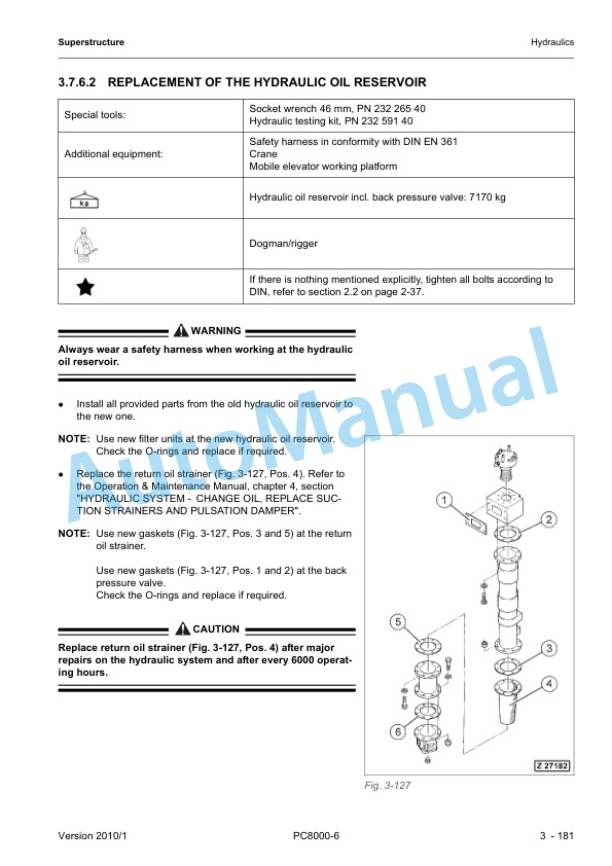
- 4.5.3. Suction oil tank with strainers
- 4.5.4. Return oil collector pipe with strainer
- 4.5.5. Back pressure valve
- 4.5.6. Transfer pump
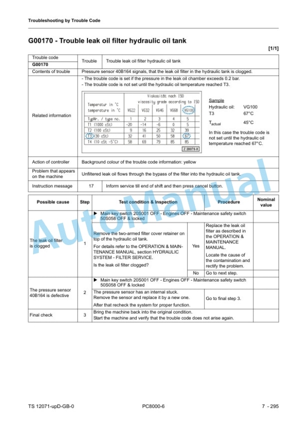
- 4.5.7. Return and leak oil filter
- 4.5.8. Breather filter
- 4.6. Hydraulic oil cooling
- 4.6.1. Overall view of the hydraulic oil cooling
- 4.6.2. Function of the hydraulic oil cooling circuit
- 4.6.3. Adjustment of the back pressure valve
- 4.6.4. Fan drive standard oil cooler
- 4.6.5. Adjustment of the cooler fan drive speed
- 4.6.6. Fan drive additional oil cooler
- 4.7. Controlling
- 4.7.1. General layout
- 4.7.2. Control and filter panels location of components
- 4.7.3. Pilot pressure supply and adjustments
- 4.7.4. Function of the electrohydraulic control system
- 4.7.5. Hand lever (joystick) control
- 4.7.6. Foot pedal control
- 4.7.7. Proportional amplifier module, type A
- 4.7.8. Proportional amplifier module, type B
- 4.7.9. Ramp time module
- 4.7.10. Adjustment of amplifier modules
- 4.7.11. Adjusting the ramp time module
- 4.8. Components
- 4.8.1. Main control blocks and high pressure filters (FSA)
- 4.8.2. Distributor manifold location of restrictor blocks and anticavitation valves
- 4.8.3. Restrictor block with secondary relief valve
- 4.8.4. Anticavitation valve (ACV) block
- 4.8.5. Remote control valves
- 4.8.6. Directional solenoid valves
- 4.8.7. Proportional solenoid valves
- 4.8.8. Highpressure filter (screen)
- 4.8.9. CONTROL blocks and valves
- 4.8.10. Travel brake valve
- 4.8.11. Pressure reducing valve
- 4.8.12. Directional valves
- 4.8.13. Pressure double stage valve
- 4.8.14. Hydraulic cylinder
- 4.9. Main hydraulic pumps and pump regulation
- 4.9.1. General
- 4.9.2. Main pumps
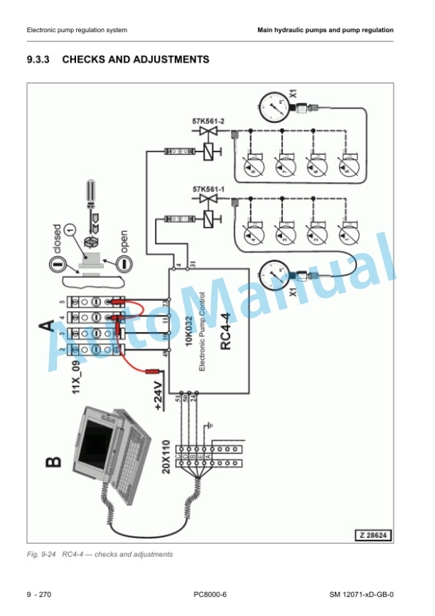
- 4.9.3. Electronic pump regulation system
- 4.9.4. Hydraulic constant regulation system
- 4.9.5. Power check (engine performance)
- 4.9.6. Engine speed sensor (pickup)
- 4.9.7. Energy efficiency
- 4.10. Operating hydraulics
- 4.10.1. General
- 4.10.2. Hydraulics for the attachment cylinders FSA
- 4.10.3. Hydraulics for the slew circuit
- 4.10.4. Hydraulics for the travel circuit
- 4.11. Hydraulic track tensioning system
- 4.11.1. General
- 4.11.2. Functional description
- 4.11.3. Doublestage valve
- 4.11.4. Tensioning cylinder
- 4.11.5. Adjustments / checks
- 4.12. Access ladder, hydraulically operated
- 4.12.1. General
- 4.12.2. Function of the hydraulically operated access ladder
- 4.12.3. Adjustments / checks
- 4.13. Central refilling system (service arm)
- 4.13.1. General
- 4.13.2. Function
- 4.14. Hints for reading the hydraulic diagram
- 4.14.1. General
- 4.14.2. Hydraulic symbols
- 4.15. Hints for reading the electric wiring diagram
- 4.15.1. General
- 4.15.2. Reference designation of the electrical components
- 4.15.3. Graphical symbols
- 4.15.4. Drawing concept
- 4.15.5. Cable marking
- 4.15.6. Table of new and old component designations
- 4.16. KOMTRAX Plus
- 4.16.1. General
- 4.16.2. Specifications for Operators
- 4.16.3. Tables of all Provided Messages
- 4.16.4. Flow Charts (14) VHMS Main Screens
- 4.16.5. VHMS Service Level
- 4.16.6. InterfaceConnection VHMSController
- 4.16.7. Wiring of the VHMSController
- 4.16.8. Global Layout of the MTC Control System
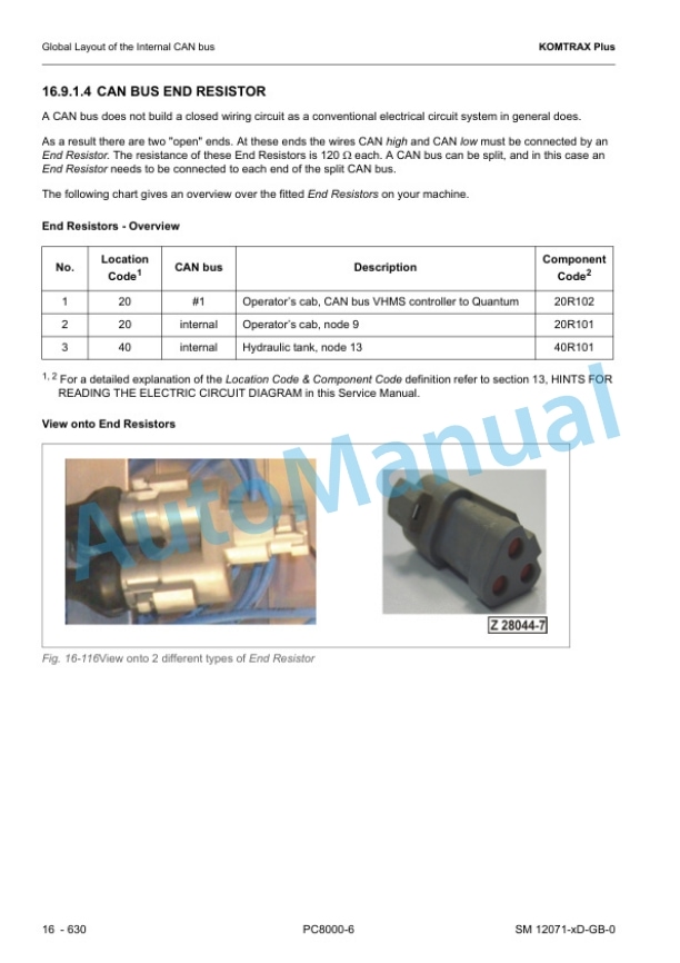
- 4.16.9. Global Layout of the Internal CAN bus
- 4.16.10. The Nodes in the CAN bus System
- 4.17. Lubrication system
- 4.17.1. General overview (SLS CLS 1 / 2)
- 4.17.2. Basic function of the lubrication systems
- 4.17.3. Central lubrication system (CLS 1 2)
- 4.17.4. Slew ring lubrication system (SLS)
- 4.17.5. Lubrication cycle
- 4.17.6. Hydraulically driven lube pump
- 4.17.7. Lubricant injectors
- 4.17.8. Vent valve
- 4.17.9. Endline switch
- 4.17.10. Inline filter
- 4.17.11. Lubricant level sensor
- 4.17.12. Commissioning
- 5. Troubleshooting
- 5.1. Introduction General Information for Troubleshooting
- 5.1.1. Overview
- 5.1.2. General Precautions
- 5.1.3. Preparations For Work
- 5.1.4. Precautions During Work
- 5.1.5. Precautions When Carrying Out Any Operation
- 5.1.6. Fundamental Requirements for Troubleshooting
- 5.1.7. Points To Remember When Trouble shooting
- 5.1.8. Sequence Of Events In Troubleshooting
- 5.1.9. Checks Before Troubleshooting
- 5.1.10. Handling Of Electric Equipment And Hydraulic Components
- 5.1.11. General working procedures
- 5.1.12. Cylinder bypass test
- 5.1.13. Information about MTC Nodes
- 5.1.14. Basics about How to crimp
- 5.1.15. Cable Shielding
- 5.1.16. KOMTRAX Plus vs. VHMS
- 5.1.17. Mounting Locations and Connector Types
- 5.1.18. Standard Value Table for Electrical Components
- 5.1.19. References for Troubleshooting (CAN Bus Node Outputs)
- 5.1.20. Tables for Testing and Troubleshooting
- 5.1.21. Troubleshooting by Trouble Code
- 5.1.22. Troubleshooting by Symptoms
- 6. Assembly Disassembly
- 6.1. Introduction
- 6.1.1. Contents of the binder
- 6.1.2. Foreword
- 6.2. Safety and standards
- 6.2.1. Safety instructions
- 6.2.2. Torque charts according to DIN
- 6.2.3. Blind plugs
- 6.2.4. Conversion table
- 6.2.5. Tools
- 6.2.6. Explanation of Abbreviations
- 6.3. Superstructure
- 6.3.1. Superstructure overview
- 6.3.2. Special preparatory work
- 6.3.3. Diesel engine
- 6.3.4. Radiators (engine coolant)
- 6.3.5. Torsion type coupling
- 6.3.7. Hydraulics
- 6.3.8. Slew system
- 6.3.9. Lubrication system
- 6.3.10. Operators cab
- 6.3.11. Cab base
- 6.3.12. Access ladder
- 6.3.13. Counterweight
- 6.3.14. Superstructure lifting
- 6.3.15. Fuel tank
- 6.4. Undercarriage
- 6.4.1. Travel system
- 6.4.2. Car body
- 6.5. Attachment
- 6.5.1. Face Shovel (FSA)
- 6.5.2. Metering valves (grease injectors) at the attachment
- 6.5.3. Cylinder bypass test
- 6.6. Service information
- 6.6.1. Fluids and lubricants
- 6.6.2. Filling capacities
- 6.6.3. Work Instructions
- 6.6.4. Used special tools (overview)
- 6.7. Tools catalogue
- 6.8. Parts Service News
Rate this product
You may also like

