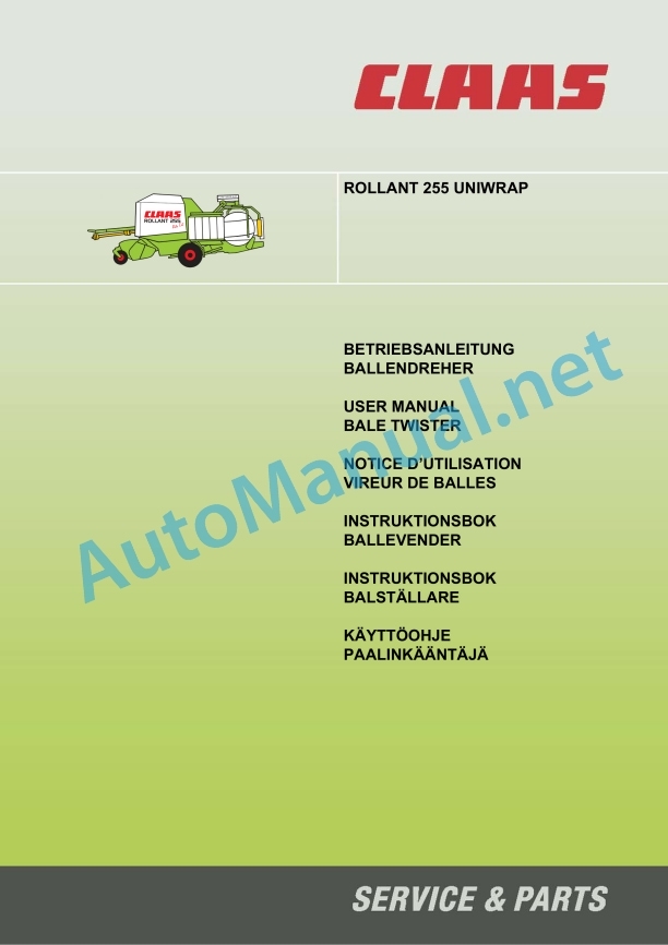
Claas Rollant 250 255 Uniwrap (726) Balers Operator Manual EN
$50.00
- Model: Rollant 250 255 Uniwrap (726) Balers
- Type Of Manual: Operator Manual
- Language: EN
- Format: PDF(s)
- Size: 44.0 MB
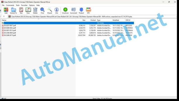
File List:
00 0297 600 7.pdf
00 0299 436 2.pdf
00 0301 051 0.pdf
00 2348 408 0.pdf
00 2348 427 0.pdf
00 0297 600 7.pdf:
1 Introduction
Introduction
2 Contents
3 General information
Road traffic
Important Information
Identification Plate/Serial Number
Identification plate (baler)
Serial number (baler)
Identification plate (bale wrapper)
Serial number (bale wrapper)
4 Safety rules
Safety Rules
Marking of warning and danger notes
Correct usage
General safety- and accident prevention regulations
Machines hitch
Hydraulic system
Tires/brakes
Maintenance
Noise level of machines at work, information “D”
Safety decals with pictograms
5 Technical specifications
Rollant 255 Roto Cut Uniwrap
Feeder mechanisms
Bale wrapper
Hydraulic system required on the tractor
Flow rate of hydraulic oil
Safety Features
Bale wrapper
6 Description and functions
Transmission of power
Cam-typt-out clutch – articulated shaft
Pickup drum
Cutting unit
Hydraulic rotor reversing unit
Bale chamber
Binding process
Bale overlap
Wrapping modes
Wrapping process
Vehicle electric lighting
Electrical unit electrical system
Control box
Stop button/Emergency stop switch
Safety arm
Hydraulic control block
Remove plate (F) to get to the hydraulic control block (from machine no. 726 01330).
Tipping body
Wrapping table
Wrapper arm
Film cutting knives
Holder for replacement film rolls
Foil roller box (from Machine No. 726 01330)
Brake system
Bale discharge belt (option)
Travelling on public roads
Pre-stretcher 82 %
Bale material-accumulation protection shaft
Worklight (optional)
Bale rotater (optional)
7 Prior to operation
Check and observe Before using the machine
Hook-up baler with bale wrapper
Hitching to the clevis or swinging drawbar with a safety nut
Tightening torque for bolts and nuts
Attaching to the swinging drawbar with a counter nut
Adjusting the length of the drawbar fork arms
Adjusting the hitch eye
Attaching to the jaw-type hitch with a counter nut
Adjusting the drawbar fork arms
Adjusting the hitch eye
Set up ball head coupling (only permitted in accordance with the customary local laws)
Before hitching the baler
Jack stand
Fitting the rubber buffer
After hooking up the baler
Connecting the universal drive shaft to the tractor
Shortening the propeller shaft
Attaching the universal drive shaft to the tractor
Connecting the brake hoses
Air Brakes
Manoeuvring the bale wrapper without air activated brake
Parking brake
Electrical
Control terminal (Control base)
CLAAS COMMUNICATOR
Power supply
Open the shut off valve of the tipping body
Before transport
Hydraulics
Connections on the tractor
Tractor with hydraulics system and constant delivery rate or load sensing system without “Power…
Tractor with hydraulic system and constant pressure
Tractor with load sensing and a “Power-Beyond” pressure connection
8 Setting up the baler/bale wrapper
Pick-up, transport and work positions
Adjusting the working height of the pick-up
Adjusting the working height of the pick-up
Pick-up wheels
Pick-up crop guard
Short crop baffle
Roller crop guard
Adjusting the roller crop guard
Adjusting the roller crop guard where there are problems with the bale material feed
Driving the baler with the roller crop guard
Blockage in the roller crop guard
Cutting unit
Blanking knives
Installing and removing the knives
Locking the knives
Knife – blanking knife holder (option)
Hydraulic baling pressure pre- adjustment
Adjusting the baling pressure with a pivoting segment
Spring tension adjustment
Safety lock for the tailgate
Net wrapping
Recommendation
Inserting the net
Setting the number of full net wrappings
V-belive for net wrapping
Double twine wrapping
Threading the twine
Threading the twine ROLLANT 255 with CLAAS Control Terminal
Adjusting the twine wrap number at twine box level
Balers with twine and net binding
V-belt drive for twine wrapping
Bale wrapper
Recommandations
Bracket for the replacement roll of film
Foil roller box
Putting a film roll in the stretcher
Placing the film in the film cutter
Bale overlap adjustment
Up to machine No.72601046
Removing the bale wrapper (depending on equipment)
9 Operation of the control terminal and the wrapper control unit
Introduction
Control terminal
Switching on the control terminal
Control Terminal – Overview
Binding and discharching the bales
Setting the type of wrapping
Automatic twine and net wrapping
Automatic twine wrapping
Automatic net binding
Start wrapping cycle manually
Delay wrapping cycle
Binding process completed
Discharging bales
Dumping bales
With an attached bale wrapper
Without a bale wrapper
Open/close tailgate
Raise/lower pickup (without floating position)
Engage/disengage knives
Cam-type cut-out clutch – universal drive shaft
Rotor reverse
Meaning of the most important symbols
Meaning of the most important symbols
Setting the number of wrappings to be made by the bale wrapper
“User settings” submenu display
User settings
Setting the delay time until the start of automatic or manual net wrapping
Automatic tailgate opening setting
Manual tailgate opening
Reload pressure
Clean knives
Select language
Wrapper menu
Daily and total counter
Reset maintenance display
Reset daily counter
Special counter
Start special counter
Correct bale count
Fault display
Error display in text mode
Switch off warning signal
Delete fault
Bale wrapper
Manual control of the discharging/wrapping processes
Manual control Start/Stop
Selecting parars
10 CLAAS COMMUNICATOR
Baler with Claas Communicator control box
Switching on the CLAAS COMMUNICATOR
Overview – CLAAS COMMUNICATOR
Incremental encoder and keys
Incremental encoder
Selector switches
Navigational keys for the menu
Application menu
Functions in the application menu
Information window in the application menu
Setup menu
Opening the adjustment sub-menu
Setting up the baler
Bale wrapper settings
Work mode of bale wrapper
Counter menu
Display window current job
Fault menu
System information menu
Operator settings
Setting up the baler
Select type of wrapping
Setting the number of net windings
Setting the twine length
Setting the delay between end of baling and start of net wrapping
Setting the automatic opening of the tailgate
Setting the recharging of the baling pressure in the hydraulic cylinder
Cleaning of cutting blades
Activating the bale wrapper
Bale wrapper settings
Selecting the »Operating mode of the wrapper«
Bale chute
Setting the number of foil layers
Settings in the counter menu
Selecting job orders
Resetting the work record counter
Resetting the daily counter
Resetting the service display
Fault display
Main menu »Service«
Opening the service menu
System information menu
Image adjustment menu
Setting the contrast
Setting the brightness
Time and date menu
Setting the time or date
Memory management menu
Administration of the saved projects
Reduce conflicts between the baler and the tractor
Language selection menu
Setting the language
Pre-settings
Pick-up function
Activate cutting unit
Check the position of the cutting facility using a sensor
Standard machines Up to machine no. 72601046 except 72600863 to 72600872
Cutting unit active From machine no. 72601047 and machine no. 72600863 up to 72600872
Cutting udeactivated From machine no. 72601047 and machine no. 72600863 up to 72600872
Recharging the cylinder pressure starting with the first bale
Process for activating the function starting with the first bale
Turn rotor back
Baling and wrapping
Automatic twine wrapping
Automatic net wrapping
Manual wrapping – twine wrapping and net wrapping
Bale output on wrapper
Automatic opening of tailgate
Opening the tailgate manually
Wrapping and bale output
Automatic bale output
Manual bale output
Bale output with bale grouping
Direct bale output without wrapping
Worklight (optional)
States of the baler
Twine wrapping without recharging the pressure
Net wrapping without recharging the pressure
Net wrapping including recharging the pressure
States of the wrapper
11 Bale wrapper operation
Automatic Monitoring
Wrapper program steps
Uniwrap control unit – Overview
Wrapping work cycle
Increasing the number of wrapper arm rotations
Resuming an interrupted wrap cycle
Discharging wrapped bales
Automatic bale discharge
Manual bale discharge
Fault reports
Tailgate manual opening to complete a wrapping cycle
Worklight (optional)
ADJUSTABLE MENUS
Adjustable parameters
Setting the operating mode
Language selection
Sensor test
Setting the film release time
Total counter zero reset
Daily counter zero reset
Setting bale discharge
Setting the number of wrapper arm turns
Start/Stop keys
Manual Control
Starting a new wrapping cycle and discharging bales
Manual raising/lowering of the tipping body
Manual raising/lowering of the wrapping table
Manual opening/closing of the film cutting knives
Manual wrapper arm rotation
12 Faults and remedies
Twine Binding
Net binding
13 After using the baler
After Using The Baler
Remove the control terminal
Control panel (ROLLANT 255 optional)
Claas Communicator (option)
Disconnection of hydraulic hoses and cables
Detach the universal drive shaft
Putting on the parking brake
Hydraulic brake
Place wheel chocks
Unhitching the baler with bale wrapper
Removing the roll of film
Cleaning the stretcher
Storing of film rolls
Cleaning the baler
Round bale transport
Storage of round bales
14 Maintenance
Important Maintenance Instructions
Hydraulic safety lock for the tailgate
Wheels/tires
Hydraulic system
Lubrication
Cutting unit
Proposals For Winter Storage
Lubricants Table
mainteNance table
Drive system
Shear bolt pickup drive
Rotor return drive unit shear bolt
Angle drive gearbox
Checking the oil level
Gearbox – wrapper arm
Tightening up the fastening bolts
Re-tightening the drive chains
Tightening the pickup drive chain (left hand side)
Tightening the drive chain for the cross conveyor auger (right hand side)
Adjusting the chain tensioner
Spring-loaded cylinder for bale forming roller drive-tailgate
Spring adjustment for bale forming roller lower drive
Spring adjustment for bale forming roller front drive
Tightening the tension spring for the net roll tensioning clamp
Tightening the tension spring (F)
Adjusting the tension spring for the net brake
Adjusting the pressure springs for the pressure roller
Adjusting the twine tensioner
Adjusting the twine tensioner
Adjusting the twine knife control
Lubrication systems
Automatic chain lubrication
Mechanical lubrication of the central chain (Option)
Overview of the mechanical lubricating pump
Making adjustments to the mechanical lubricating pump
Lubricants
Central lubrication system for lubricatable bearings (optional)
Automatic central lubrication of the bearing (Option)
Adjusting the flow rate
Setting the stop on the grease pump
Filling the grease container
Cutting unit
Hydraulic oil filter
Fire extinguisher (Rollant 255 optional)
Clean the rollers (Rollant 255)
Brakes/Tires
Air brakes
Pneumatically-controlled filter
Cleaning the screen filters
Draining the air reservoir
Brake cylinder
Adjusting the brake lever
Brake linings
Wheel nut tightening check
Checking the bearing clearance of the wheel hub
Adjusting the bearing play
Flat belts
Fitting on the flat belts
Repairing the flat belts
Repair set
Bale wrapper adjustments
Adjusting the safety arm
Adjusting the sensors on the wrapper arm
Film cutting knives, protective plate for the stretchers
Sensor “bale in the tipping body”
Sensor “tipping body is down”
Tipping body roller
Wrapping table limit switch
Wrapping table sensor
Opening angle of the film cutting knives
Film cutting knives
15 Lubrication plan
00 0299 436 2.pdf:
Introduction
Sicherheitsvorschriften
Kennzeichnung von Warn- und Gefahrenhinweisesen
Allgemeine Sicherheits- und Unfallverhütungsv Abstellen der Maschine
Bestimmunggemäße Verwendung
SAFETY STICKER WITH WARNBILDZEICHE
Technische Daten
Ballendreher bedienen
3-WAY VALVE
Description of 3-Way Valves
The function of the 3-way valve
3-way valve operation
Ballenwindler ohne Ballendreher bedienen
Transportstellung des Ballendrehers
Balenwindler mit Ballendreher bedienen
ABLAGESEITE DES BALLENS
Select Ablageseite des Ballens
Ablage des Ballens nach links
Ablage des Ballens nach rechts
Ablageseite des Ballens umstellen
Ballendreher the fitter
Änderung der Montage der Sicherheitsbefestigung (Ballenderher with the original lock)
Änderung der Montage der Sicherheitsbefestigung (Ballenderher mit der optimiten Verriegelung)
Set the locking system
Additional settings of the fastening (Ballender with the original lock)
Abstand Gehäuse / Ballendreher einstellen
Alignment Befestigungsstrebe / Verriegelungsbolzen einstellen
Additional settings of tstening (Ballender with optimized lock
Abstand Gehäuse / Ballendreher einstellen
Alignment Befestigungsstrebe / Verriegelungsbolzen einstellen
BALL TURN IN WORK POSITION
Sicherheitsbefestigungen ausbauen
Ballendreher entriegeln
In Arbeitsstellung bringen
Anordnung der Hebel
BALL TURN IN TRANSPORT STELLUNG
Wickeltisch sink
Hebel the fitter
In Transportstellung bringen
Sicherheitsbefestigungen montieren
Verriegelung für den Transport
BALLENDER REHER THE OPERATOR
Ballenablage
Steuerkasten Uniwrap
Bale twister function
Activate the Bale twister function
Function Bale twister ausschalten
Ballendreher demontieren und montieren
BALL TURN THE DISASSEMBLER
Preparation
Bügel ausbauen
Den Ballendreher von der Presse mit Ballenwickler abnehmen
BALL TURN THE ASSEMBLY
Wickeltisch sink
The Ballendreher argument
Introduction
Safety Rules
Identification of warning and danger signs
General safety precautions andcident prevention
Parking the machine
Intended use
SAFETY DECALS WITH PICTORIALS
Technical specifications
Operating bale twister
THREE-WAY VALVE
Description of three-way valve
Functions of three-way valve
Three-way valve operation
Operating wrapper without bale twister
Transport position of bale twister
Operating wrapper with bale twister
BALE EJECTION SIDE
Choice of bale ejection side
Ejecting bale to left
Ejecting bale to right
Changing bale ejection side
Fitting bale twister
Modification to assembly procedure for safety fixing (Bale twister with initial interlock)
Modification to assembly procedure for safety fixing (Bale twister with optimized interlock)
Adjustments to locking system
Additional adjustments to fixing (Bale twister with initial interlock)
Adjusting housing/twister clearance
Adjusting fixing lug/locking pin alignment
Additional adjustments to fixing (Bale twister with optimized interlock)
Adjusting housing/twister clearance
Adjusting fixing lug/locking pin alignment
BALE TWISTER IN WORK POSITION
Removing safety fixings
Unlocking bale twister
Setting to work position
Release of livers
BALE TWISTER IN TRANSPORT MODE
Lowering wrapping table
Fittings are supplied
Setting in transport mode
Fitting safety fixings
Locking for transport
OPERATING BALE TWISTERS
Ejecting bales
Uniwrap control box
Bale twister function
Triggering Bale twister function
Deactivating the Bale twister function
Disassembling and assembling bale twister
DISASSEMBLY BALE TWISTER
Preparation
Disassembling clips
Disassembling bale twister from wrapping table
ASSEMBLING BALE TWISTERS
Lowering wrapping table
Setting bale twister in position
Introduction
Consignes de sécurité
Characterization of indications sur les dangers
Consignes générales de sécurité et de prévention des accidents
Parking of the machine
zation conforme à la destination
AUTOCOLLANTS DE SÉCURITÉ AVEC SYMBOLES D’AVERTISSEMENT
Technical characteristics
Utilization du vireur de balls
VANNE TROIS VOIES
Description de la vanne trois voies
Fonctions de la vanne trois voies
Utilization de la vanne trois voies
Utilization de l’enrubanneuse sans vireur de balls
Position Transport du vireur de balles
Utilization de l’enrubanneuse avec vireur de balls
CÔTÉ DE DÉPOSE DE LA BALLE
Choix du côté de dépose de la bale
Dépose de la balle vers la gauche
Dépose de la balle vers la droite
Modification du côté de dépose de la bale
Montage du vireur de balles
Modification du montage de la fixation de sécurité (Vireur de balles avec lockout initial)
Modification of the mounting of the security fixation
Settings of the locking system
Additional settings for fixation
Adjustment of carter spacing / vireur de balls
Adjustment of the alignment patte de fixateau
Additional fixation settings
Adjustment of carter spacing / vireur de balls
Adjustment of the alignment patte de fixation / axis de lockeau
VIREUR DE BALLES EN POSITION TRAVAIL
Disassembly of the security fixings
Déverrouillage du vireur de balls
Mise en position travail
Rangement des leviers
Utilization
VIREUR DE BALLES EN POSITION TRANSPORT
Descente de la table d’enrubannage
Montage des leviers
Mise en position transport
Installation of security fixings
Verrouillage pour le transport
UTILIZATION DU VIREUR DE BALLES
Dépose de balls
Boîtier de commande Uniwrap
Function Bale twister
Activation of the Bale twister function
Deactivation of the Bale twister function
Démontage et montage du vireur de balles
DÉMONTAGE DU VIREUR DE BALLES
Preparation
Démontage des étriers
Désassemblage du vireur de balls de la table d’enrubannage
MONTAGE DU VIREUR DE BALLES
Descente de la table d’enruse en place du vireur de balls
Introduction
Safety rules
Marking of hazard notices
General rules for safety and accident prevention
Parking the machine
Intended use
ADHESIVE WARNING LABELS WITH DANGER SYMBOLS
Technical specifications
Use of bale turners
THREE WAY VALVE
Description of three-way valve
Functions of the three-way valve
Use of three-way valve
Use of a press with round bale packs without a bale turner
Bale turner in Transport position
Use of a press with round bale packs with a bale turner
PAGE FOR READING THE ROUND BALLS
Choice of side for unloading the round bales
Unloading balls on the left side
Unloading balls on the right side
Changing sides for unloading round bales
Installation of bale turners
Changed installation of the safety attachment (Bale turner with original safety)
Changed installation of the safety attachment (Bale turner with improved safety)
Adjustment of security system
Additional adjustment of safety attachment (Bale turner with original safety)
Adjustment of gearbox/bale turner distance
Adaptation fixing bracket / securing bolt
Additional adjustment of safety attachment (Bale turner with improved safety)
Adjustment of gearbox/bale turner distance
Adaptation fixing bracket / securing bolt
BALL TURNER IN WORK POSITION
Dismantling of safety fasteners
Unlocking the bale returner
Put the bale turner in working position
Connecting the slides
BALL TURNER IN TRANSPORT POSITION
Lowering the packing table
Assembly of the slides
Put the bale turner in the transport position
Installation of safety fasteners
Insurance for transport
USE OF BALL ENDERS
Remove the balls
Uniwrap control panel
Bale Twister function
Activation of the Bale twister function
Deactivation of the Bale twister function
Dismantling and assembly of the bale turner
BALE TUNER DISASSEMBLY
Preparations
Dismantling of clamps
Disconnecting the bale turner from the packing table
BALE TUNER ASSEMBLY
Lowering the packing table
Installation of bale turners
Introduction
Safety instructions
Symbols for warning and driving instructions
General instructions for safety and accident prevention
Parking the machine
Use in accordance with the purpose
SAFETY DECALS WITH WARNING SYMBOLS
Technical characteristics
Use of the baler stand
THREE WAY VALVE
Description of the three-way valve
The functions of the three-way valve
Use of the three-way valve
Use of the baler with inserters for bales without the baler
Position Transport for the balställaren
Use of the press with the bale rack
SIDA FOR RAISING BALE
Selection of the side for raising the bale
Raising the bale to the left
Raising the bale to the right
Changing the side for raising the bale
Assembling the bale rack
Change the installation of the transport lock (balställare with original lock)
Change thmounting of the transport lock (ballasts with optimized lock)
Setting the locking system
Complementary settings för fästet (Balställare with original lock)
Setting the distance between angle housing/ballast
Setting the line position transport lock/lock pin
Further adjustments to the bracket (Balställare with optimized lock)
Adjusting the angle housing/bale stand distance
Setting the line position transport lock/lock pin
BALSTÄLLARE IN OPERATION POSITION
Dismantling the transport lock
Unlock the baluster
Position operation
Fit the transport safety
BALSTÄLLARE IN TRANSPORT POSITION
Lowering the loading table.
Installation of the transport fuses
Position transport
Transport location
Locking before transport
USING THE BALSTÄLLAR
Ball raising
Uniwrap terminal
Bale twister function
Activation of the Bale twister function
Deactivate the Bale twister function
Assembly and disassembly of the b
DISASSEMBLY OF THE BALL STAY
Preparation
Dismantling the jumpers
Dismantling the bale rack from the packing table
ASSEMBLY OF THE BALL STÄLLAR
Lowering the loading table
Mount the baluster
Introduction
Turvallisuusohjeita
Varoittawien ja vaaraa ammouavien erättningen sättää
Turvallissätja ja kallenuksien väätämistä ääää äyäsohjeet
Wife parking
Intended use
TURVATARRAT VAROITUSMERKINTÖINEEN
Technical information
Paalinkääntäjän käytä
KOLMIASENTOINE VENTTIILI
Kolmiasentois valve description
The functions of the Kolmiasentoisen valve
Kolmiasentoise valventin öyää
Paalain-käärijäkäätälmän ääää ilman paalinkääntäjää
Paalinkäantäjän Kuljetus-asento
Paalinkääntäjällä varussetun paalaimen köyää
PAALIEN PUDOTUSPUOLI
Paalien pudotuspuolen valjaja
Paalien pudotus left
Paalien pudotus oikelle
Paalien pudotuspuolen muuuttanning
Paalinkääntäjän installation
Changing Turvaakiinnickeen kynytyksen muuttanning
The law of the Lukitus system
Kiinnitysen pääkäsätäut
Distance adjustment
Kiinnitykoukun/lukitustapin täläuksen nättää
Kiinnitysen säläsätätät
Distance adjustment
Kiinnitykoukun / kiinnitykoukun
PAALINKÄÄNTÄJÄ TYÖ-ASENNOSSA
Turvakiinnikketten irrotus
Paalinkääntäjän lukitusken avaus
Siirtyminen Työ-utsövät
Rajoitin lattojen tøysning
PAALINKÄÄNTÄJÄ KULJETUS-ASENNOSSA
Käärintäsäudyn lasku
Rajoitin lattojen sättö
Siirtyminen Kuljetus position
Turvakiinnikkätten lookisi
Lukitus követsta värn
PAALINKÄRIMEN KÄYTTÖ
Köyöyohjeet paalien pudotusta waarten
Uniwrap control unit
Bale twister function
Bale twister function activation
The Bale twister function is disabled
Paalinkääntäjän irrotus ja sässö ällheen
PAALINKÄÄNTÄJÄN PURKU
Preparation room
Kiinnikketten irrotus
Paalinkääntäjän irrotus klasku
Installation
00 0301 051 0.pdf:
PROFI CAM 3
Table of contents
1 Introduction
1.1 Notes on the manual
1.1.1 Validity of manual
1.1.2 Information about this Operator’s Manual
1.1.3 Symbols and notes
1.1.4 Optional equipment
1.1.5 Qualified specialist workshop
1.1.6 Maintenance information
1.1.7 Warranty notes
1.1.8 Spare parts and technical questions
1.2 Intended use
1.2.1 Intended use
1.2.2 Reasonably foreseeable misuse
2.1 Identifying warnings
2.1.1 Hazard signs
2.1.2 Signal word
2.2 Safety rules
2.2.1 Meaning of Operator’s Manual
2.2.2 Observing safety decals and warnings
2.2.3 Optional equipment and spare parts
3 Product description
3.1 Overview and method of operation
3.1.1 How the PROFI CAM works
3.2 Identification plates and identification number
3.2.1 Position of identification plates
3.2.2 Explanation of PROFI CAM identification plate
3.3 Information on the product
3.3.1 CE marking
4 Operating and control elements
4.1 Camera system
4.1.1 Camera system monitor
4.2 Menu structure
4.2.1 Main menu
4.2.2
4.2.3
4.2.4
4.2.5
4.2.6
5 Technical specifications
5.1 PROFI CAM
5.1.1 Monitor
5.1.2 Camera
5.1.3 Switch box
5.1.4 Degree of protection against foreign bodies and water
6 Preparing the product
6.1 Shutting down and securing the machine
6.1.1 Switching off and securing the machine
6.2 Prior to operation
6.2.1 Carry out prior to operation
6.2.2 Installing the sun protection
6.2.3 Aligning the camera
6.2.4 Connecting the camera electrics
7 Operation
7.1 Monitor
7.1.1 Switching on the monitor
7.1.2 Calling up the menu
7.1.3 Setting a menu item
7.1.4 Setting the image orientation
7.1.5 Setting automatic screen darkening
7.1.6 Image mirroring
7.1.7 Setting the trigger view
7.1.8 Setting the follow-up time for trigger view
7.1.9 Setting the display mode
7.1.10 Activating/deactivating a display mode
8 Faults and remedies
8.1 Electrical and electronic system
8.1.1 Overview of problems on PROFI CAM camera system
8.1.2 Replacing the switch box fuse
9 Maintenance
9.1 Maintenance intervals
9.1.1 Every 10 operating hours or daily
9.2 Camera system
9.2.1 Checking the camera system for dirt
9.2.2 Cleaning the camera
9.2.3 Cleaning the switch box
9.2.4 Cleaning the monitor
10 Placing out of operation and disposal
10.1 General Information
10.1.1 Putting out of operation and disposal
11 Technical terms and abbreviations
11.1 Abbreviations
11.1.1 Units
11.1.2 Abbreviations
11.1.3 Technical terms
00 2348 408 0.pdf:
Table of contents
1 Introduction
1.1 General information
1.1.1 Validity of the manual
1.1.2 Information about this Operator’s Manual
1.1.3 Symbols and notes
1.2 Intended use
1.2.1 Intended use
1.2.2 Reasonably foreseeable misuse
2.1 Safety rules
2.1.1 General safety and accident prevention regulations
2.1.2 Interaction between terminal and machine or tractor
2.1.3 Electrocution by electrical system
3 Product description
3.1 Overview and method of operation
3.1.1 Overview of CEMIS 100
3.1.2 Function principle of CEMIS 100
3.2 Identification plates and identification numbers
3.2.1 Spare parts and technical questions
3.2.2 Identification plate of CEMIS 100
4 Operating and display elements
4.1 CEMIS 100
4.1.1 User interface for LINER
4.1.2 User interface for ROLLANT
4.1.3 User interface for UNIWRAP
5 Technical specifications
5.1 CEMIS 100
5.1.1 Specification
6 Operation
6.1 CEMIS 100
6.1.1 Operating the CEMIS 100
6.1.2 Switching CEMIS 100 on
6.1.3 Switching CEMIS 100 off
7 Maintenance
7.1 CEMIS 100
7.1.1 Daily
8 Putting out of operation and disposal
8.1 General information
8.1.1 Removal from service and disposal
9 Technical terms and abbreviations
9.1 Terms and explanations
9.1.1 Technical words
9.1.2 Abbreviations
00 2348 427 0.pdf:
Table of contents
1 Introduction
1.1 General information
1.1.1 Validity of the manual
1.1.2 Information about this Operator’s Manual
1.1.3 Symbols and notes
1.2 Intended use
1.2.1 Intended use
1.2.2 Reasonably foreseeable misuse
2.1 Safety rules
2.1.1 General safety and accident prevention regulations
2.1.2 Interaction between terminal and machine or tractor
2.1.3 Electrocution by electrical system
3 Product description
3.1 Overview and method of operation
3.1.1 Overview of CEMIS 700
3.1.2 Function principle of CEMIS 700
3.2 Identification plates and identification numbers
3.2.1 Spare parts and technical questions
3.2.2 Identification plate of CEMIS 700
4 Information on the product
4.1 Software version
5 Operating and display elements
5.1 CEMIS 700
5.1.1 User interface
5.1.2 Terminal program
6 Technical specifications
6.1 CEMIS 700
6.1.1 Specification
7 Operation
7.1 CEMIS 700
7.1.1 Operating the CEMIS 700
7.1.2 Switching CEMIS 700 on
7.1.3 Switching CEMIS 700 off
7.2 Terminal settings
7.2.1 Making settings
Making settings with the rotary button
Making settings with the touch function
7.2.2 Setting the screen lighting
Daytime mode
Nighttime mode
Activating automatic key lighting
7.2.3 Setting the time and date
7.2.4 Displaying diagnosis information
On-board power supply voltage display
Display of CLAAS ISOBUS ECU address and name
7.2.5 Setting the language and display formats
Setting the language
Setting display formats
7.2.6 Setting the volume
7.2.7 Deleting an ISOBUS implement
8 Maintenance
8.1 Maintenance
8.1.1 Daily
9 Putting out of operation and disposal
9.1 General information
9.1.1 Removal from service and disposal
10 Technical terms and abbreviations
10.1 Terms and explanations
10.1.1 Technical words
10.1.2 Abbreviations
John Deere Repair Technical Manual PDF
John Deere Application List Component Technical Manual CTM106819 24AUG20
John Deere Repair Technical Manual PDF
John Deere Parts Catalog PDF
John Deere Tractors 6300, 6500, and 6600 Parts Catalog CQ26564 (29SET05) Portuguese
John Deere Repair Technical Manual PDF
John Deere Repair Technical Manual PDF
John Deere Repair Technical Manual PDF
John Deere Repair Technical Manual PDF
John Deere Repair Technical Manual PDF
New Holland Service Manual PDF

