Claas ARES 697-617 ATZ (A03) Tractor Repair Manual DE
$100.00
- Model: ARES 697-617 ATZ (A03) Tractor
- Type Of Manual: Repair Manual
- Language: DE
- Format: PDF(s)
- Size: 210 MB
File List:
– Contents.pdf
– Chapter A0 – Overview.pdf
– Chapter A1 – CONTROL PROCEDURES INJECTION DATA SHEETS.pdf
– Chapter A2 – INJECTION DE 10 Engine DPS 4045 TRT 73,.pdf
– Chapter A3 – ENGINE TIER II, engine DPS 4045 TRT 73.pdf
– Chapter B0 – Overview.pdf
– Chapter B1 – MECHANICAL PART.pdf
– Chapter B2 – HYDRAULIC PART.pdf
– Chapter B3 – ELECTRONIC PART.pdf
– Chapter C0 – Overview.pdf
– Chapter C1 – MECHANICAL PART.pdf
– Chapter C2 – HYDRAULIC PART.pdf
– Chapter C3 – ELECTRONIC PART.pdf
– Chapter D0-PR – Overview.pdf
– Chapter D0-PS – Overview.pdf
– Chapter D1-PR – MECHANICAL PART.pdf
– Chapter D1-PS – MECHANICAL PART.pdf
– Chapter D2-PR – PART HYDRAULICS.pdf
– Chapter D2-PS – PART HYDRAULICS.pdf
– Chapter D3-PR – PART ELECTRONICS.pdf
– Chapter D3-PS – ELECTRONIC PART.pdf
– Chapter E0 – Overview.pdf
– Chapter E1 – COMMON COMPONENTS.pdf
– Chapter E2 – OPEND CENTER 60 L MIN.pdf
– Chapter E3 – LOAD SENSING 100 L MIN.pdf
– Chapter E4 – LOAD SENSING 110 L MIN.pdf
– Chapter F0-40 – Overview.pdf
– Chapter F0-50 – Overview.pdf
– Chapter F1-40 – LIST OF COMPONENT CABLE HARNESSES AND GENERAL LIST up to No. A0301319 A0500978.pdf
– Chapter F1-50 – LIST OF COMPONENTS CABLE HARNESSES AND GENERAL LIST FROM SERIAL NUMBERS A0301320 A0500979.pdf
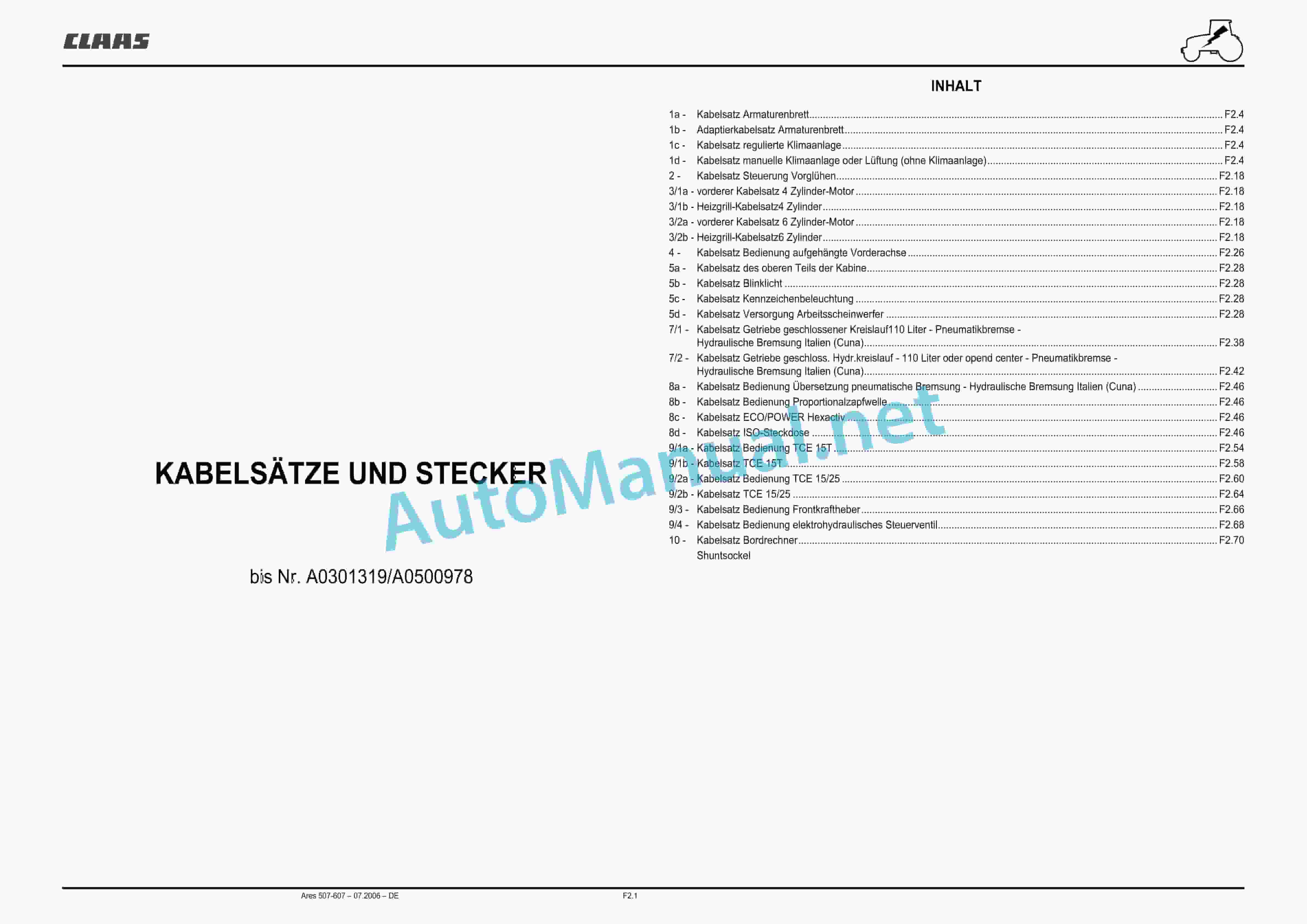
– Chapter F2-40 – CABLE SETS AND CONNECTORS up to No. A0301319 A0500978.pdf
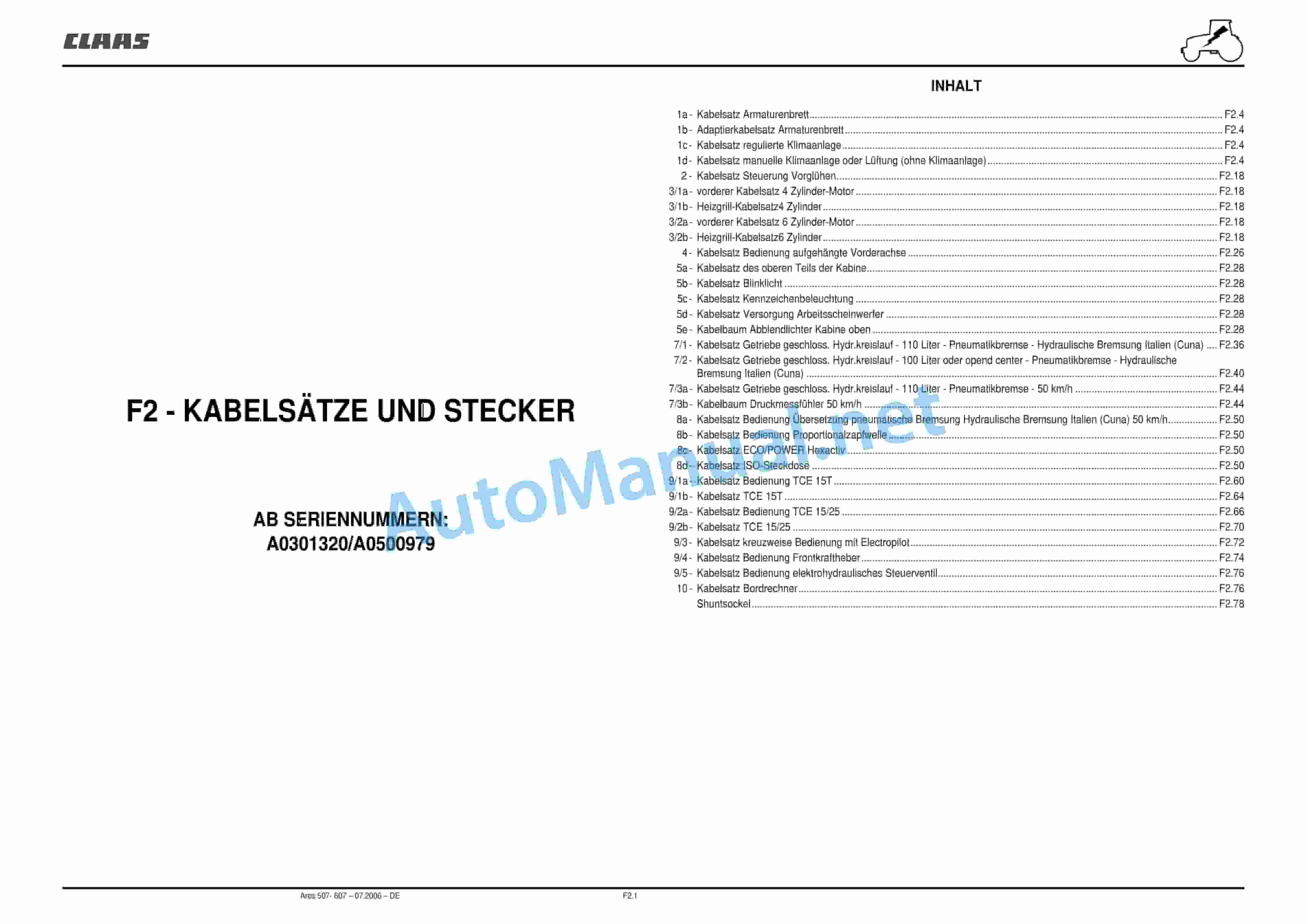
– Chapter F2-50 – CABLE HARNESSES AND CONNECTORS FROM SERIAL NUMBERS A0301320 A0500979.pdf
– Chapter G0 – Overview.pdf
– Chapter G1 – DASHBOARD.pdf
– Chapter G2 – ELECTRONIC POWER LIFT TCE 15 T.pdf
– Chapter G3 – ELECTRONIC HITCH TCE 15 25.pdf
– Chapter G4 – INFOTRAC AND ISO CONNECTION.pdf
– Chapter G5 – ELECTROPILOT.pdf
– Chapter G6 – USER MANUAL WIN MTADIAG.pdf
– Chapter H0 – Overview.pdf
– Chapter H1 – RAISING THE DRIVER’S CAB AND GLUING THE WINDOWS.pdf
– Chapter H2 – HEATING AIR CONDITIONING (MANUAL).pdf
– Chapter H3 – REGULATED HEATING AND AIR CONDIT- FRONT POWER SHAFT.pdf
– Chapter J3 – PNEUMATIC BRAKE.pdf
– Chapter J4 – TOOLS.pdf
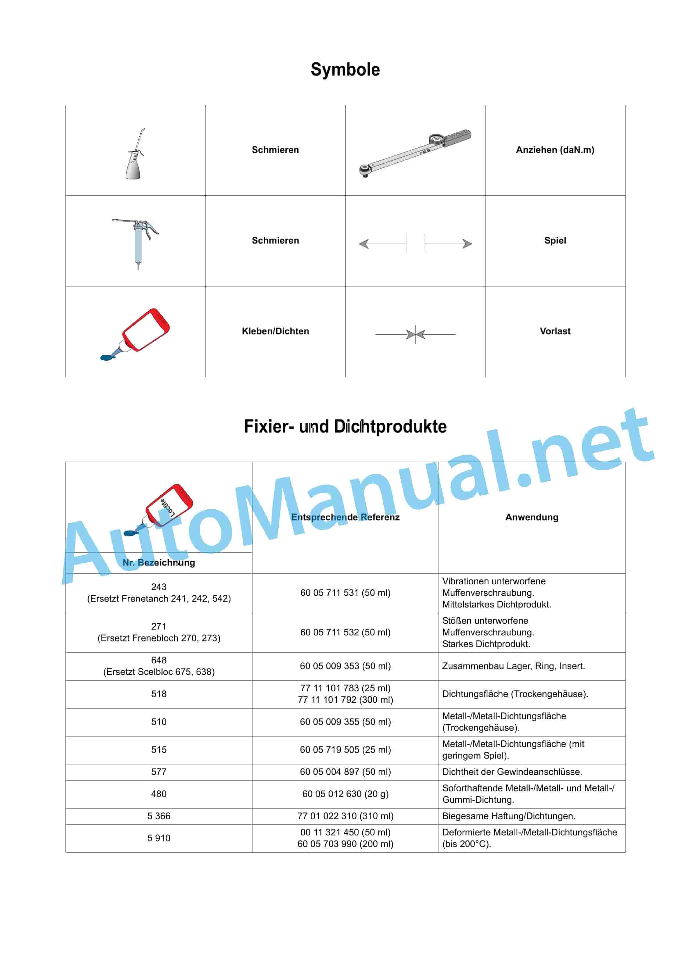
– Chapter symbols, fixing and sealing products, hydraulic lines, standardized tightening torques.pdf
Contents.pdf
Table of Content:
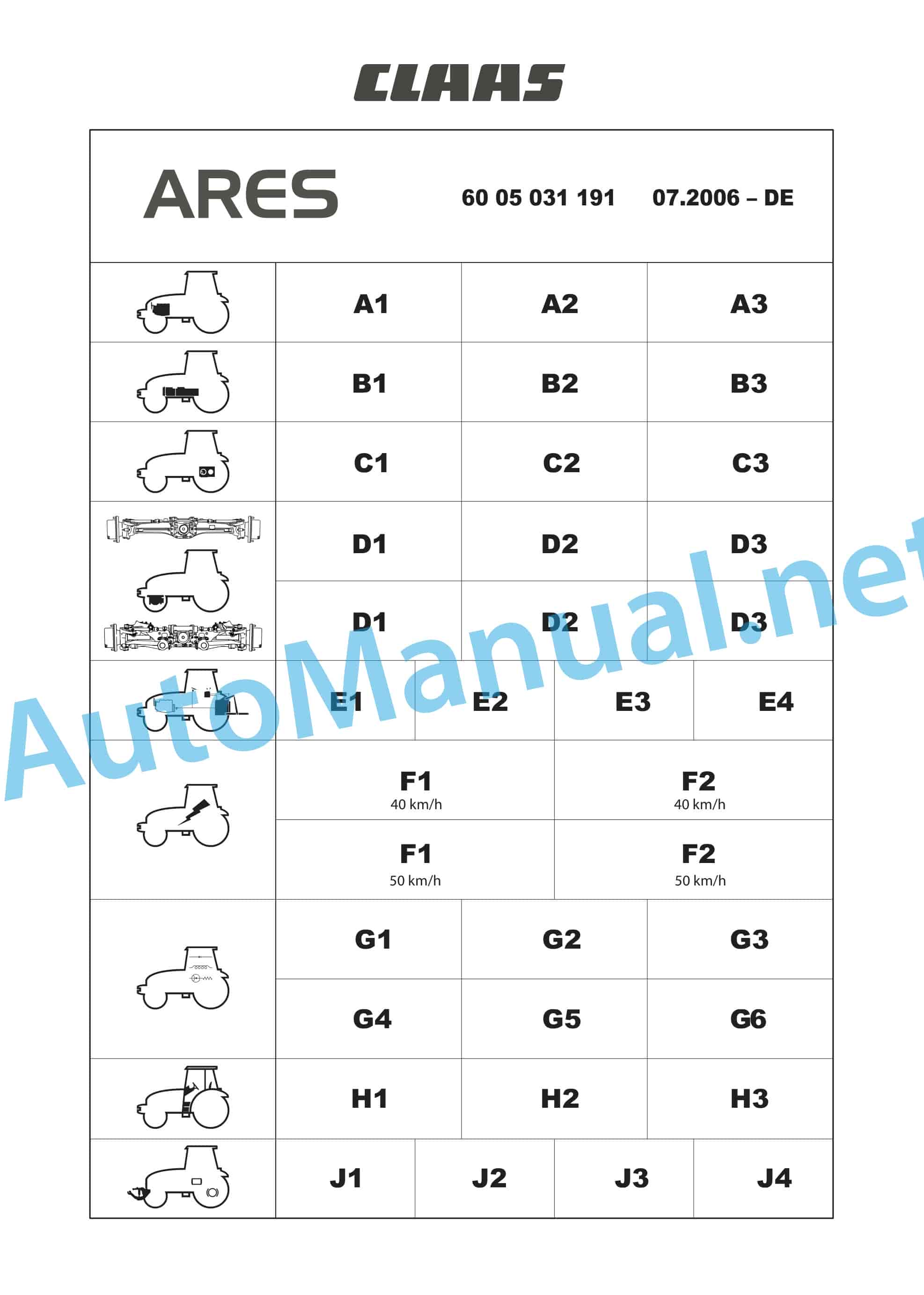
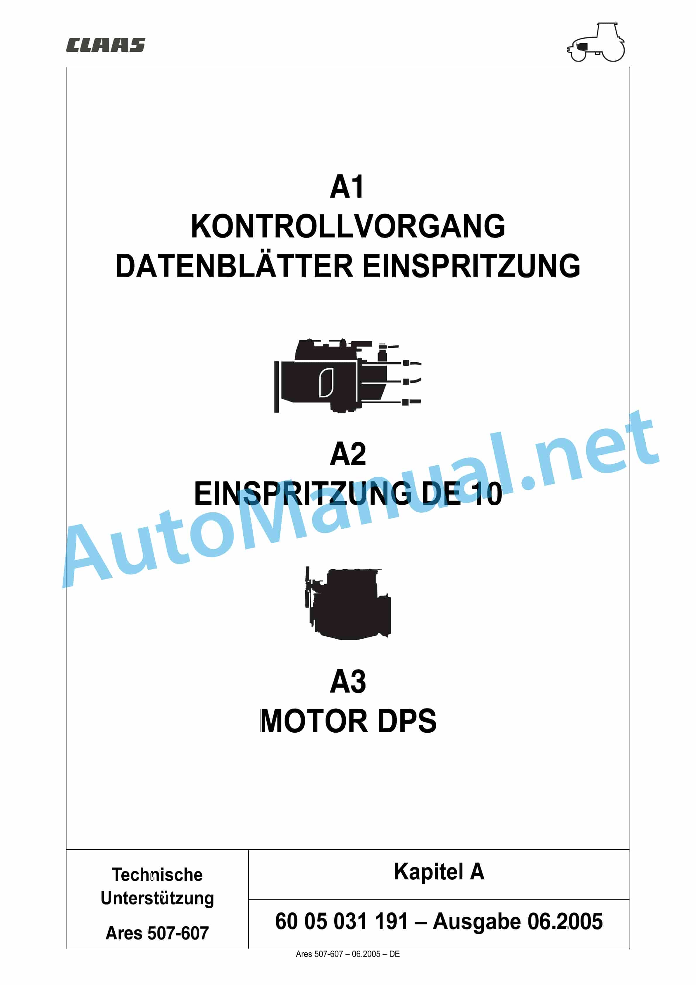
2 A1 CHECKING PROCESS INJECTION DATA SHEETS
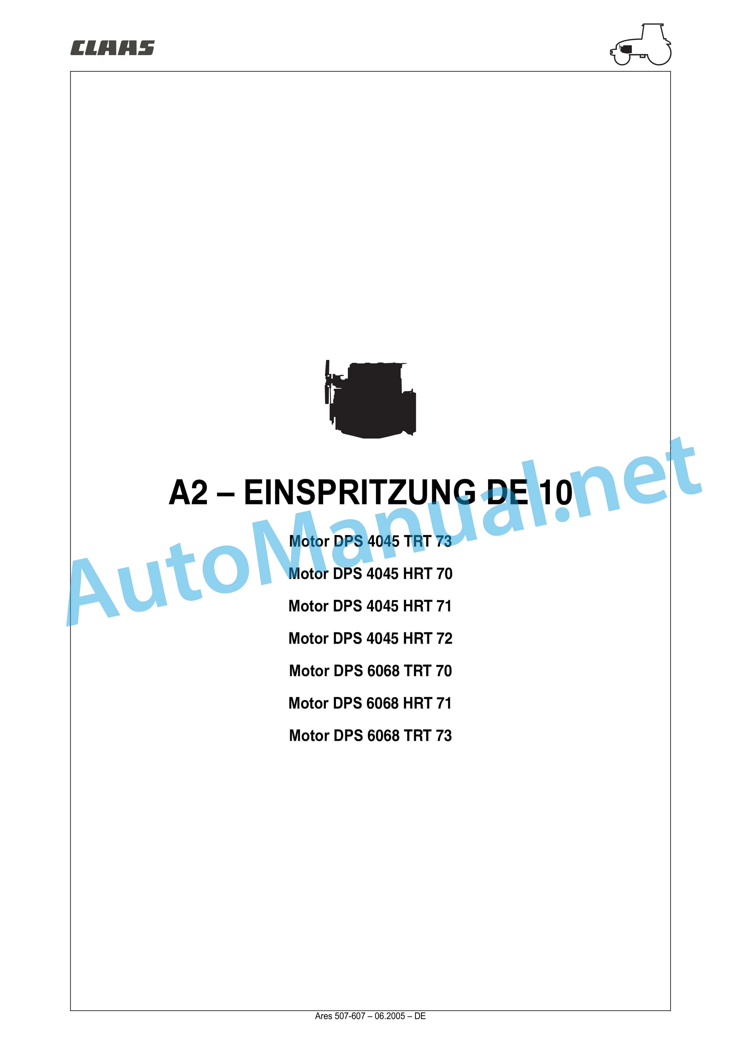
3 A2 INJECTION DE 10
4 A3 ENGINE TIER II
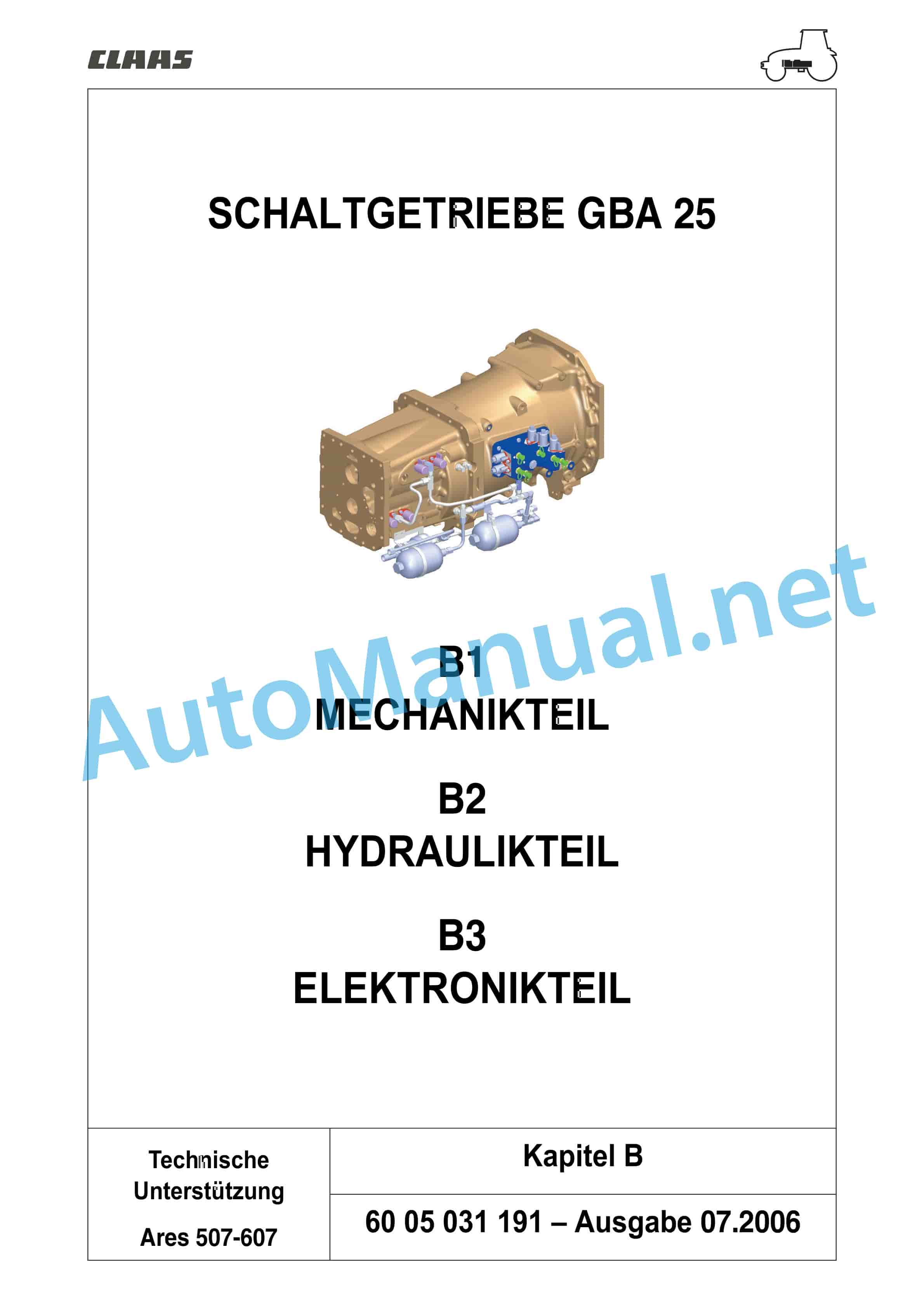
5 MANUAL TRANSMISSION GBA 25 – B1 PART MECHANICAL
6 MANUAL TRANSMISSION GBA 25 – B2 PART HYDRAU”LOAD SENSING” 110 L/MIN
21 F1 – LIST OF COMPONENTS CABLE HARNESSES AND GENERAL LIST – 40 km/h
22 F2 – CABLE HARNESSES AND CONNECTORS – 40 km/h
23 F1 – LIST OF COMPONENTS – CABLE HARNESSES AND GENERAL LIST – 50 km/h
24 F2 – CABLE HARNESSES AND CONNECTORS – 50 km/h
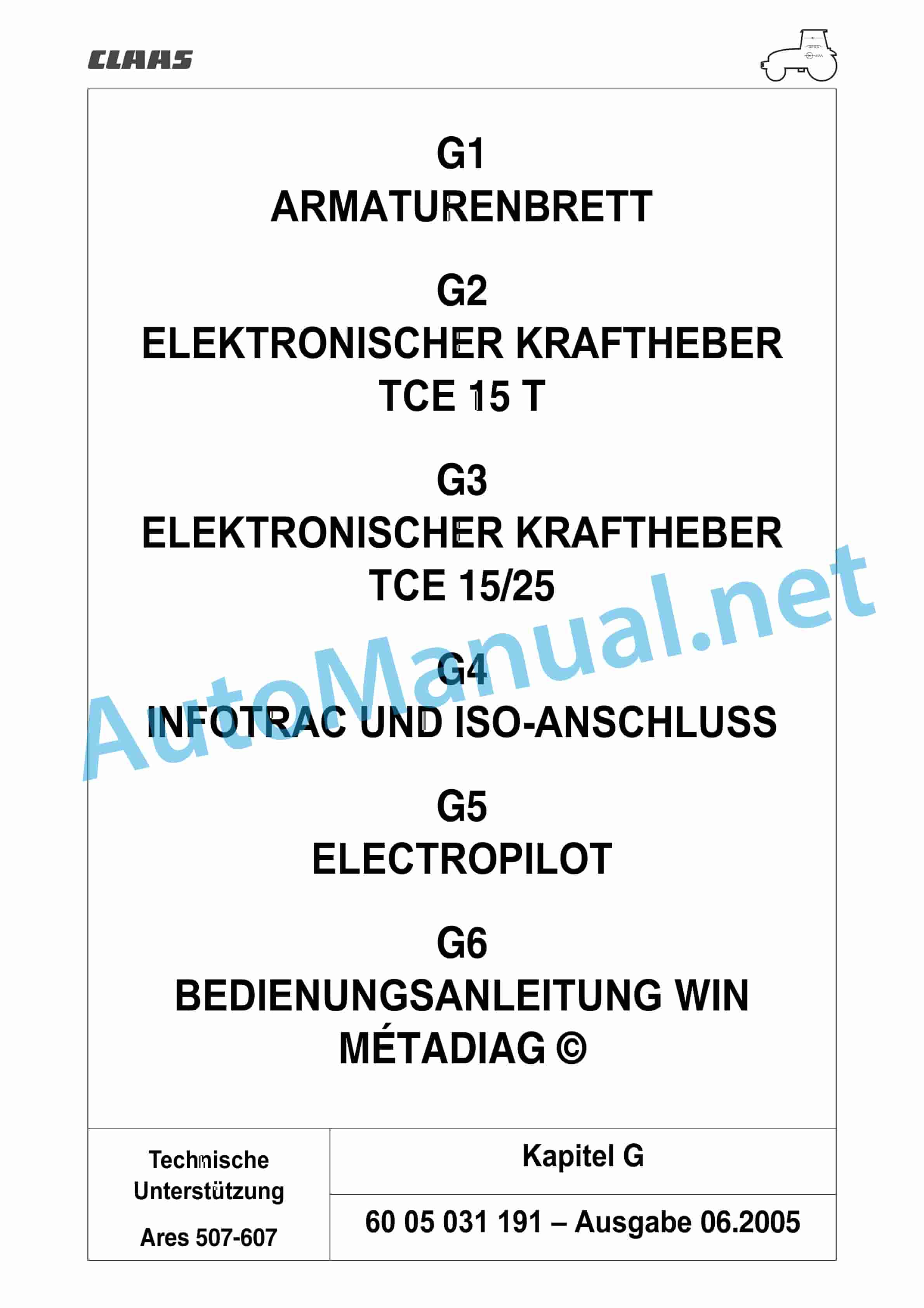
25 G1 DASHBOARD
26 G2 – ELECTRONIC POWER LIFT TCE 15 T
27 G3 ELECTRONIC HITCH TCE 15/25
28 G4 INFOTRAC AND ISO CONNECTION
29 G5 – ELECTROPILOT
30 G6 – USER MANUAL WIN MTADIAG
31 H1 RAISING THE DRIVER CAB AND GLUING THE WINDOWS
32 H2 – HEATING/ntrol procedures
1.2 Measuring and control points
1.3 Appendix
1.4 INJECTION DATA SHEET
2 CONTENTS ARES 507 / 607
Chapter A2 – INJECTION DE 10 Engine DPS 4045 TRT 73,.pdf
Table of Content:
1 A2 INJECTION DE 10
1.1 Overview
1.2 Description and functionality
1.3 Further technical information
1.4 Tightening torques
1.5 Filter element
1.6 Injection pump
1.7 Injector
1.8 Electronic regulation
1.9 Collector air temperature sensor
1.10 Engine coolant temperature sensor
1.11 Fuel temperature sender
1.12 Crankshaft position sensor
1.13 Pump control solenoid
1.14 Accelerator pedal meter
2 CONTENTS ARES 507 / 607
Chapter A3 – ENGINE TIER II, engine DPS 4045 TRT 73.pdf
Table of Content:
1 A3 ENGINE TIER II
1.1 General description
1.2 Solid parts technology
1.3 Technology of moving parts
1.TENTS ARES 507 / 607
Chapter B0 – Overview.pdf
Table of Content:
1 MANUAL TRANSMISSION GBA 25 – B1 PART MECHANICAL
2 MANUAL TRANSMISSION GBA 25 – B2 PART HYDRAULIC
3 MANUAL TRANSMISSION GBA 25 – B3 ?”Hexashift”
1.3 Module switchable under load reversing circuit
1.4 Module robotized switching groups
1.5 Modules of the creeper gear switching groups
1.6 Characteristics GBA 25
1.7 Kinematics GBA 25
1.8 Expansion
1.9 Main Settings
1.10 Tightening torques and sealing products
1.11 Module “Hexashift”
1.12 Module switchable under load reversing circuit
1.13 Module robotized switching groups
1.14 Creep speed switching group
1.15 Extra creep speed”Load Sensing” 100 l/min
1.6 “Load Sensing” 110 l/min
1.7 Tightening torques of the control circuit
1.8 Measuring points and solenoid valve control
1.9 Measuring points and control control GBA 25
1.10 Data sheet Determination of control values?”Recording the control values ?”Recording the control values ?”Load Sensing” 100 l/min”
1.15 measuring points and control of “Load Sensing” 110 l/min
1.16 Data sheet “Recording the control values ?”Load Sensing” 110 l/min”
2 CONTENTS ARES 507 / 607
Chapter B3 – ELECTRONIC PART.pdf
Table of Content:
1 B3 PART ELECTRONICS
1.1 Electronic transmission control
1.2 Electronic transmission control
1.3 Arrangement of components
1.4 Elec”Aisles and security”
1.7 Measuring and control points “Supply”
1.8 Measuring and control points of the “Hexashift”
1.9 Measuring and control points “Robotized switching group”
1.10 Measuring and control points “reverse switch that can be switched under load”
1.11 Measuring and control points “Operating mode management”
1.12 Measuring and control points “Overdrive”
1.13 Measuring and control points for the “Creep speed” group
1.14 Measuring and control points “Display”
2 CONTENTS ARES 507 / 607
Chapter C0 – Overview.pdf
Table of Content:
1 C1 PART MECHANICAL
2 C2 PART HYDRAULIC
3 C3 ?”HD”
1.4 Rear axle funnel “SHD”
1.5 Bevel gear and differential
1.6 Rear PTO clutch
1.7 Upper rear power take-off shaft
1.8 Lower rear power take-off shaft
1.9 Encoder and PTO shaft operation
1.10 Proportional PTO
1.11 Service brake 40km/h translation
1.12 Service brake 50km/h translation
1.13 Handbrake 40km/h translation
1.14 handbrake 50km/h translation
2 CONTENTS ARES 507 / 607
Chapter C2 – HYDRAULIC PART.pdf
Table of Content:
1 C2 – PART HYDRAULIC
1.1 Low pressure circuit (LP circuit) 20bar
1.2 Braking function40km/h
1.3 Braking function50km/h
1.4 Lubrication circuit
1.5 Opend Center 60l/min
1.6 “Load Sensing” 100l/min
1.7 “Load Sensing” 110l/min
1.8 Tightening torques
1.9 Measuring points and control of the Open Center 60l/min
1.10 Data sheet “Recording the control values “Recording the control values ?”Load Sensing” 100l/min”
1.13 Measuring points and control of “Recording the control values ?”Load Sensing” 110l/min”
1.15 Brake line transmission (version 40km/h
1.16 Brake line transmission (version 50km/h)
2 CONTENTS ARES 507 / 607
Chapter C3 – ELECTRONIC PART.pdf
Table of Content:
1 C3 ELECTRONIC PART
1.1 Electronic management of the rear axle
1.2 Arra”Hydraulics low pressure (LP)”
1.5 Measuring and control points “Engine speed”
1.6 Measuring and control points “Supply”
1.7 Measuring and control points “All-wheel drive (4 wheel drive)
1.8 Measuring and control points “Differential lock”
1.9 Measuring and control points “PTO shaft”
1.10 Measuring and control points “Braking”
2 CONTENTS ARES 507 / 607
Chapter D0-PR – Overview.pdf
Table of Content:
1 D1 PART MECHANICAL
2 D2 PART HYDRAULIC
3 D3 PART ELECTRONICS
4 CONTENTS ARES 507 / 607
Chapter D0-PS – Overview.pdf
Table of Content:
1 D1 PART MECHANICAL
2 D2 PART HYDRAULIC
3 D3 PART ELECTRONICS
4 CONTENTS ARES 507 / 607
Chapter D1-PR – MECHANICAL PART.pdf
Table of Content:
1 D1 MECHANICAL PART
1.1 General
1.2 Main ti
1.9 Cardan shaft
1.10 Drive bevel gear and differential
1.11 Transmission (4 wheel drive)
2 CONTENTS ARES 507 / 607
Chapter D2-PR – PART HYDRAULICS.pdf
Table of Content:
1 D2 PART H”Determination of control values”
2 CONTENTS ARES 507 / 607
Chapter D2-PS – PART HYDRAULICS.pdf
Table of Content:
1 D2 PART HYDRAULIC
1.1 Description
1.2 How it works
1.3 Component”Recording the control values”
1.7 Hydraulic block
2 CONTENTS ARES 507 / 607
Chapter D3-PR – PART ELECTRONICS.pdf
Table of Content:
1 D3 PART ELECTRONICS
1.1 Front axle
1.2 Gearbox (4 wheel drive)
2 CONTENTS ARES 507 / 607
Chapter D3-PS – ELECTRONIC PART.pdf
Table of Content:
1 D3 PART ELECTRONICS
1.1 Description
1.2 Diagnosis
1.3 Settings
1.4 Measuring and control points
2 CONTENTS ARES 507 / 607
Chapter E0 – Overview.pdf
Table of Content:
1 E1 COMMON COMPONENTS
2 E2 ?”SNR” works
1.4 How the brake valve “Cuna” works
1.5 Steering housing
1.6 Additional valves
1.7 Power lift
1.8 Brake valve
2 CONTENTS ARES 507 / 607
Chapter E2 – OPEND CENTER 60 L MIN.pdf
Table of Content:
1 E2 OPEND CENTER 60 L/MIN
1.1 Overview
1.2 Arrangement of components
1.3 Right cover
1.4 Left cover
1.5 Hydraulic m”Determination of hydraulic control values”
1.8 Hydraulic measuring and control points
1.9 Data sheet “Determination of hydraulic control values”
2 CONTENTS ARES 507 / 607
Chapter E3 – LOAD SENSING 100 L MIN.pdf
Table of Content:
1 E3 LOAD SENSING?”Determination of hydraulic control values”
1.8 Hydraulic measuring and control points
1.9 Data sheet “Determination of hydraulic control values”
2 CONTENTS ARES 507 / 607
Chapter E4 – LOAD SENSING 110 L MIN.pdf
Table of Content:
1 E4 LOAD SENSING”Determination of hydraulic control values”
1.10 Hydraulic measuring and control points
1.11 Data sheet “Determination of hydraulic control values”
2 CONTENTS ARES 507 / 607
Chapter F0-40 – Overview.pdf
Table of Content:
1 F1 – LIST OF COMPONENTS CABLE HARNESSES AND GENERAL LIST
2 F2 – CABLE HARNESSES AND CONNECTORS
3 CONTENTS ARES 507 / 607
Chapter F0-50 – Overview.pdf
Table of Content:
1 F1 – LIST OF COMPONENTS CABLE HARNESSES AND GENERAL LIST
2 F2 – CABLE HARNESSES AND CONNECTORS
3 CONTENTS ARES 507 / 607
Chapter F1-40 – LIST OF COMPONENTS CABLE HARNESSES AND GENERAL LIST up to No. A0301319 A0500978.pdf
Table of Content:
1 F1 – LIST OF COMPONENTS – CABLE HARNESSES AND GENERAL LIST
1.1 List of components
1.2 Cable harnesses and general list
1.3 CONTENT
1.4 Abbreviations
1.5 Fuse box and relay version regulated air conditioning
1.6 Allocation of conductors
1.7 Fuse box and relay version manual ventilation and air conditioning
1.8eating – engine speed
1.12 Low beam – High beam – Rotating lights – Horn
1.13 Front work lights (regulated climate control)
1.14 Front work lights (manual climate control)
1.15 Rear work lights
1.16 Brake light – front axle switched on – operation of solenoid valve pneumatic brake
1.17 Parking lights – dashboard lighting
1.18 Turn signals and hazard lights
1.19 Cigar lighter – clock – radio – antenna – ceiling light and spotlight
1.20 Air Suspension Seat – Front PTO Clutch
1.21 Windshield wipers / washers front and rear
1.22 Ventilation dashboard
1.23 Ventilation dashboard and manual air conditioning
1.24 Ventilation dashboard and regulated air conditioning
1.25 On-board computer – ISO socket
1.26 Handbrake – Brake fluid level – Hydraulic brake Italy(Cuna)
1.27 Calibration dashboard – diagnostic socket dashboard and TCE 15T – diagnostic display
1.28 Connector 25 A
1.29 Gearbox hydraulic pressure – Gearbox oil temp. – Oil filter clogging (60 liters and 100 liters closed circuit)
1.30 Hydraulic Pressure Transmission – Temp. Transmission Oil – Oil Filter Clogging (110Liter Closed Center)
1.31 Tractor travel speed – Rear PTO speed
1.32 Engine oil pressure – Air filter clogging – SupplyTCE
1.33 Fuel level – engine cooling temperature
1.34 Operation4Drive wheels/differential – rear PTO shaft/proportional PTO shaft
1.35 Electropilot – Front power lift
1.36 Power lift TCE15T
1.37 Power lift TCE15/25
1.38 Gearbox computer supply
1.39 Hexashift/Hexactiv
1.40 Operation clutch and forward travel
1.41 CAN main network
1.42 CAN network dashboard – power lift TCE15/25 – programming socket
1.43 Motor control
1.44 Suspended front axle
2 CONTENTS ARES 507 / 607
Chapter F1-50 – LIST OF COMPONENTS CABLE HARNESSES AND GENERAL LIST FROM SERIAL NUMBERS A0301320 A0500979.pdf
Table of Content:
1 F1 – LIST OF COMPONENTS – CABLE HARNESSES AND GENERAL LIST
1.1 List of components
1.2 Cable harnesses and general list
1.3 CONTENT
1.4 Abbreviations
1.5 Fuse box and relay version regulated air conditioning(110)
1.6 Allocation of conductors
1.7 Fuse box and relay manual ventilation and air conditioning version(110)
1.8 Allocation of conductors
1.9 Relay and fuse box, cabin top(111)
1.10 Allocation of conductors
1.11 Installation locations of the earth conductors
1.12 Designation of the masses
1.13 Starter circuit – charging circuit – preheating – engine speed
1.14 Low beam – Low beam cabin top – High beam – Rotating lights – Horn
1.15 Front work lights (regulated and manual air conditioning without electric rear-view mirror)
1.16 Front work lights(manual air conditioning with electric rearview mirror)
1.17 Rear work lights
1.18 Brake light – front axle switched on – operation of solenoid valve pneumatic brake
1.19 Parking lights – dashboard lighting
1.20 Turn signals and hazard lights
1.21 Cigar lighter – clock – radio – antenna – ceiling light and spotlight
1.22 Air Suspension Seat – Front PTO Clutch
1.23 Windshield wipers / washers front and rear
1.24 Rear side window defrosting – operation of electric rearview mirrors
1.25 Ventilation dashboard
1.26 Ventilation dashboard and manual air conditioning
1.27 Ventilation dashboard and regulated air conditioning
1.28 On-board computer – ISO socket
1.29 Braking50km/h Gearbox – Handbrake
1.30 Handbrake – Brake fluid level – Hydraulic brake Italy(Cuna)
1.31 Calibration dashboard – diagnostic socket dashboard and TCE 15T – diagnostic display
1.32 Connector 25 A
1.33 Gearbox hydraulic pressure – Gearbox oil temp – Oil filter clogging (60 liters and 100 liters closed circuit)
1.34 Hydraulic pressure transmission – temp. transmission oil – clogging of the oil filter (110 liter closed center) – 50 km/h
1.35 Tractor travel speed – Rear PTO speed
1.36 Engine oil pressure – Air filter clogging – SupplyTCE
1.37 Fuel level – engine cooling temperature
1.38 Operation4Drive wheels/Differential – Rear PTO/Proportional PTO
1.39 Electropilot – front power lift
1.40 power lift TCE15T
1.41 Power lift TCE15/25
1.42 Gearbox computer supply
1.43 Hexashift/Hexactiv
1.44 Operation of the clutch and forward travel
1.45 Creep speed
1.46 CAN main network
1.47 CAN network dashboard – power lift TCE15/25 – programming socket
1.48 Motor control
1.49 Suspended front axle
1.50 Crosswise operation with Electropilot
2 CONTENTS ARES 507 / 607
Chapter F2-40 – CABLE SETS AND CONNECTORS up to No. A0301319 A0500978.pdf
Table of Content:
1 F2 – CABLE HARNESSES AND CONNECTORS
1.1 Abbreviations
1.2 Cable sets and plugs
1.3 1a – Dashboard cable set
1.4 1b – Adapter cable set dashboard
1.5 1c – cable set regulated air conditioning
1.6 1d – Cable set for manual air conditioning or ventilation (without air conditioning)
1.7 2 – Cable set for pre-glow control
1.8 3/1a – front cable set 4 cylinder engine
1.9 3/1b – heating grill cable set 4 cylinders
1.10 3/2a – front cable set 6 cylinder engine
1.11 3/2b – Heating grill cable set6 cylinders
1.12 4 – Cable set for operating suspended front axle
1.13 5a – Cable harness of the upper part of the cabin
1.14 5b – Cable set for flashing light
1.15 5c – License plate lighting cable set
1.16 5d – cable set supply worklight
1.17 7/1 – Gearbox cable set closed. Hydraulic circuit – 110 liters – Pneumatic brake – Hydraulic braking Italy (Cuna)
1.18 7/2 – Transmission cable set closed. Hydraulic circuit – 100 liters or opend center – Air brake – Hydraulic braking Italy (Cuna)
1.19 8a – Cable set operation translation pneumatic braking – hydraulic
1.20 8b – Cable set for operating proportional power take-off shaft
1.21 8c – Cable set ECO/POWER Hexactiv
1.22 8d – Cable set ISO socket
1.23 9/1a – Cable set operation TCE 15T
1.24 9/1b – Cable set TCE 15T
1.25 9/2a – Cable set operation TCE 15/25
1.26 9/2b – cable set TCE 15/25
1.27 9/3 – Cable set for front power lift operation
1.28 9/4 – Cable set for operating electro-hydraulic control valve
1.29 10 – Cable set on-board computer
1.30 shunt socket
2 CONTENTS ARES 507 / 607
Chapter F2-50 – CABLE SETS AND CONNECTORS FROM SERIAL NUMBERS A0301320 A0500979.pdf
Table of Content:
1 F2 – CABLE HARNESSES AND CONNECTORS
1.1 CONTENT
1.2 Abbreviations
1.3 Cable sets and plugs
1.4 1a – Cable set dashboard
1.5 1b – Adapter cable set dashboard
1.6 1c – cable set regulated air conditioning
1.7 1d – Cable set for manual air conditioning or ventilation (without air conditioning)
1.8 2 – Cable set for pre-glow control
1.9 3/1a – front cable set 4 cylinder engine
1.10 3/1b – Heating grill cable set 4 cylinders
1.11 3/2a – front cable set 6 cylinder engine
1.12 3/2b – heating grill cable set6 cylinders
1.13 4 – Cable set for operating suspended front axle
1.14 5a – Cable harness of the upper part of the cabin
1.15 5b – Cable set for flashing light
1.16 5c – License plate lighting cable set
1.17 5d – cable set supply worklight
1.18 5e – Wiring harness for low beam cabin top
1.19 7/1 – Gearbox cable set closed. Hydraulic circuit – 110 liters – Pneumatic brake – Hydraulic braking Italy (Cuna)
1.20 7/2 – Gearbox cable set closed. Hydraulic circuit – 100 liters or opend center – Air brake – Hydraulic braking Italy (Cuna)
1.21 7/3a – Gearbox cable set closed. Hydraulic circuit – 110 liters – pneumatic brake – 50 km/h
1.22 7/3b – Wiring harness pressure sensor 50km/h
1.23 8a – Cable set operation translation pneumatic braking – hydraulic
1.24 8b – Cable set for operating proportional power take-off shaft
1.25 8c – Cable set ECO/POWER Hexactiv
1.26 8d – Cable set ISO socket
1.27 9/1a – Cable set operation TCE 15T
1.28 9/1b – cable set TCE 15T
1.29 9/2a – Cable set operation TCE 15/25
1.30 9/2b – cable set TCE 15/25
1.31 9/3 – Cable set for front power lift operation
1.32 9/4 – Cable set for operating electro-hydraulic control valve
1.33 9/5 – Cable set for operating electro-hydraulic control valve
1.34 10 – Cable set on-board computer
1.35 shunt socket
2 CONTENTS ARES 507 / 607
Chapter G0 – Overview.pdf
Table of Content:
1 G1 DASHBOARD
2 G2 ELECTRONIC HITCH TCE 15 T
3 G3 ELECTRONIC HITCH TCE 15/25
4 G4 INFOTRAC AND ISO CONNECTION
5 G5 ELECTROPILOT
6 G6 – USER MANUAL WIN MTADIAG
7 CONTENTS ARES 507 / 607
Chapter G1 – DASHBOARD.pdf
Table of Content:
1 G1 DASHBOARD
1.1 Overview
1.2 Technical d”Infotrac”
1.2 Presentation of ISO socket
1.3 Removal/reinstallation and electrical checks
1.4 Settings
2 CONTENTS ARES 507 / 607
Chapter G5 – ELECTROPILOT.pdf
Table of Content:
1 G5 – ELECTROPILOT
1.1 Overview
1.2 Control valves
1.3 Electro-hydraulic control valve
1.4 Further technical information
1.5 Removal/reinstallation
1.6 Control
1.7 Measuring and control points
1.8 Sheet “Recording of control values”
2 CONTENTS ARES 507 / 607
Chapter G6 – USER MANUAL WIN MTADIAG.pdf
Table of Content:
1 G6 – USER MANUAL WIN MTADIAG
1.1 CONTENT
1.2 Updating the software versionsWinMtadiag
1.3 Connection of WinMtadiag
1.4 Application Motor
1.5 Application gearbox
1.6 Application Gear Display
1.7 Application rear PTO shaft
1.8 Application Dashboard
1.9 Application Electropilot
1.10 Application regulated air conditioning
2 CONTENTS ARES 507 / 607
Chapter H0 – Overview.pdf
Table of Content:
1 H1 07EATING AIR CONDITIONING (MANUAL).pdf
Table of Content:
1 H2 – HEATING/AIR CONDITIONING (MANUAL)
1.1 Technical data
1.2 General description
1.3 Arrangement of components
1.4 Description and functionality
1.5 Safety instructions
1.6 Draining and admitting gas
1.7 Removal/reinstallation
1.8 Diagnosis
2 CONTENTS ARES 507 / 607
Chapter H3 – REGULATED HEATING AND AIR CONDITIONING.pdf
Table of Content:
1 H3 REGULATED HEATING AND AIR CONDITIONING
1.1 Regulated air conditioning
2 CONTENTS ARES 507 / 607
Chapter J0 – Overview.pdf
Table of Content:
1 J1 FRONT HITCH AND MOUNTING POINTS
2 J2 FRONT PTO
3 J3 ?”Control values”
2 CONTENTS ARES 507 / 607
Chapter J2 – FRONT POWER SHAFT.pdf
Table of Content:
1 J2 FRONT PTO
1.1 Front”Recording of control values”
2 CONTENTS ARES 507 / 607
Chapter J3 – PNEUMATIC BRAKE.pdf
Table of Content:
1 J3 PNEUMATIC BRAKE
1.1 General description
1.2 Representation of the different systems
1.3 Technical terms
1.4 Description of components
1.5 Overview
1.6 Functionality
1.7 Tightening torques and sealing products
1.8 Measuring and control points
2 CONTENTS ARES 507 / 607
Chapter J4 – TOOLS.pdf
Table of Content:
1 J4 TOOLS
1.1 TOOLS PER CHAPTER
2 CONTENTS ARES 507 / 607
Chapter symbols, fixing and sealing products, hydraulic lines, stand
5/5 - (489 votes)
John Deere Repair Technical Manual PDF
John Deere PowerTech M 10.5 L and 12.5 L Diesel Engines COMPONENT TECHNICAL MANUAL CTM100 10MAY11
John Deere Repair Technical Manual PDF
John Deere DF Series 150 and 250 Transmissions (ANALOG) Component Technical Manual CTM147 05JUN98
John Deere Repair Technical Manual PDF
John Deere Repair Technical Manual PDF
John Deere Parts Catalog PDF
John Deere Tractors 6300, 6500, and 6600 Parts Catalog CQ26564 (29SET05) Portuguese
John Deere Repair Technical Manual PDF
John Deere Repair Technical Manual PDF
John Deere Repair Technical Manual PDF
John Deere Repair Technical Manual PDF

