Claas ATLES 946-926 RZ (A01) Tractor Repair Manual DE
$100.00
- Model: ATLES 946-926 RZ (A01) Tractor
- Type Of Manual: Repair Manual
- Language: DE
- Format: PDF(s)
- Size: 92.8 MB
File List:
– Chapter A – Overview.pdf
– Chapter A0 – CHECKING PROCESS INJECTION DATA SHEETS.pdf
– Chapter A1 – SUPPLY INJECTION.pdf
– Chapter A2 – ENGINE TIER II.pdf
– Chapter B – Overview.pdf
– Chapter B1 – FULL POWERSHIFT TRANSMISSION GBA 32.pdf
– Chapter B2 – LOW PRESSURE HYDRAULIC CIRCUIT GTA 3230.pdf
– Chapter B3 – REPAIR TRANSMISSION (AG 250).pdf
– Chapter C – Overview.pdf
– Chapter C1 – REAR AXLE GPA 30.pdf
– Chapter C2 – SERVICE BRAKE AND HANDBRAKE.pdf
– Chapter C3 – PARK LOCK.pdf
– Chapter D – Overview.pdf
– Chapter D1 – FRONT AXLE 750.102, 750.119.pdf
– Chapter D2 – PTO CASING 4 DRIVE WHEELS GPA 30.pdf
– Chapter E – Overview.pdf
– Chapter E1 CLOSED HYDRAULICS (110 l min) (except control circuit, see chapter B2.pdf
– Chapter F – Overview.pdf
– Chapter F1 – LIST OF COMPONENTS CABLE HARNESSES AND GENERAL LIST.pdf
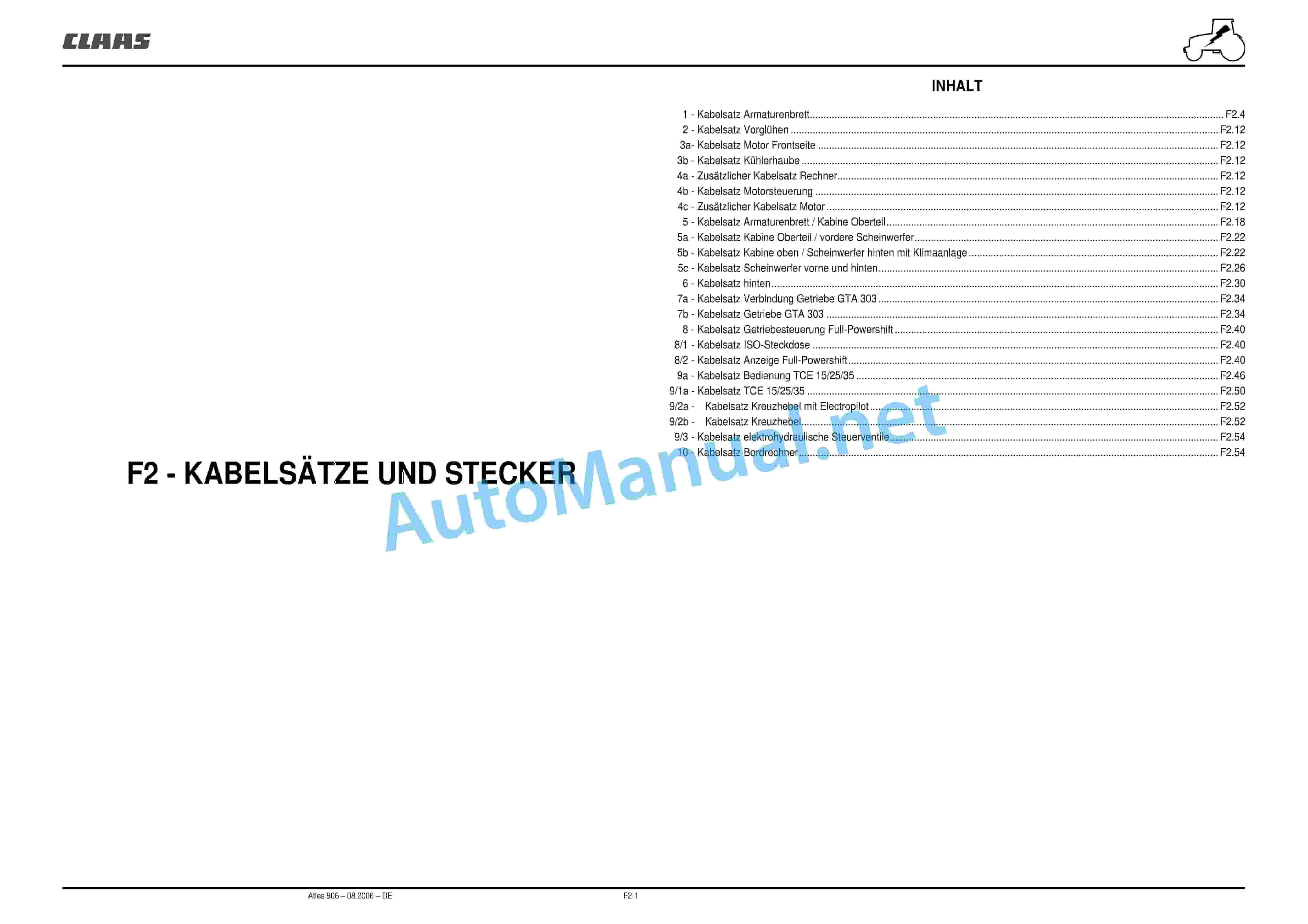
– Chapter F2 – CABLE HARNESSES AND CONNECTORS.pdf
– Chapter G – Overview.pdf
– Chapter G1 – DASHBOARD.pdf
– Chapter G2 – ELECTRONIC HITCH TCE 25.pdf
– Chapter G3 – MANAGEMENT OF POWER TRANSMISSION AXLE.pdf
– Chapter G4 – ENGINE CONTROL.pdf
– Chapter G5 – INFOTRAC AND ISO CONNECTION.pdf
– Chapter G6 – ELECTROPILOT.pdf
– Chapter G7 – USER MANUAL WIN METADIAG ATLES 906.pdf
– Chapter H – Overview.pdf
– Chapter H1 – RAISING THE CABIN.pdf
– Chapter H2 – HEATING AIR CONDITIONING.pdf
– Chapter H3 – GLUING THE DISCS.pdf
– Chapter J – Overview.pdf
– Chapter J1 – FRONT HITCH AND FRONT PTO.pdf
– Chapter J2 – PNEUMATIC BRAKE.pdf
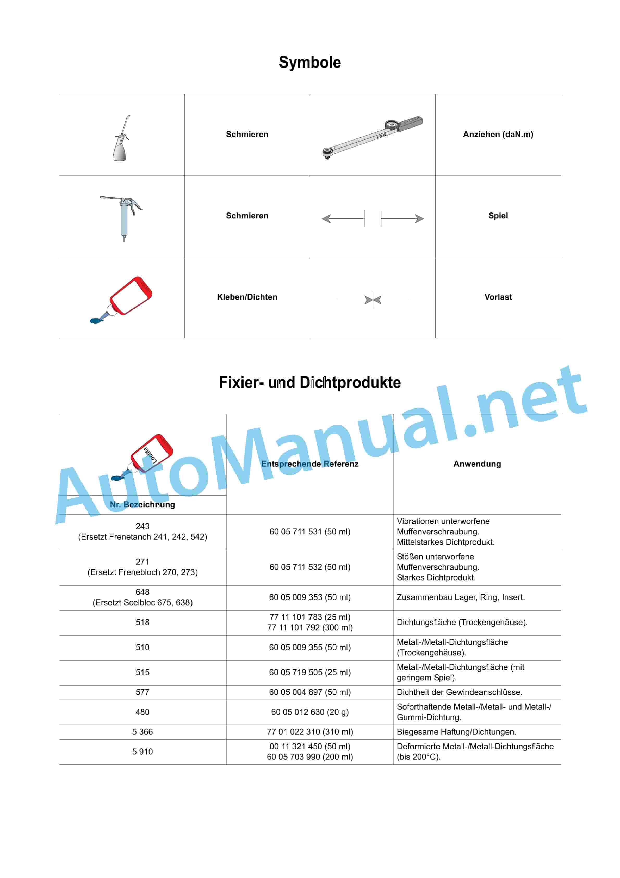
– Chapter symbols, fixing and sealing products, hydraulic lines, standardized tightening torques,.pdf
Chapter A – Overview.pdf
Table of Content:
1 A0 CHECKING PROCESS INJECTION DATA SHEETS
2 A1 SUPPLY INJECTION
3 A2 ENGINE TIER II
Chapter A0 – CHECKING PROCESS INJECTION DATA SHEETS.pdf
Table of Content:
1 A0 CHECKING PROCESS INJECTION DATA SHEETS
1.1 Control procedures
NJECTION.pdf
Table of Content:
1 A1 SUPPLY INJECTION
1.1 Identifier
1.2 Tightening torques
1.3 Description
1.4 Controls and Settings
1.5 Removal/reinstallation
Chapter A2 – ENGINE TIER II.pdf
Table of Content:
1 A2 ENGINE TIER II
1.1 General Specifications
1.2 Dimensions
1.3 Tightening torques
1.4 Controls and Settings
1.5 Removal/reinstallation
Chapter B – Overview.pdf
Table of Content:
1 B1 GEARBOX GBA 32 FULL POWERSHIFT
2 B2 LOW PRESSURE HYDRAULIC CIRCUIT GTA 3230
3 B3 – REPAIR: GEARBOX(AG250)
Chapter B1 – FULL POWERSHIFT TRANSMISSION GBA 32.pdf
Table of Content:
1 B1 FULL POWERSHIFT TRANSMISSION GBA 32
1.1 General
1.2 Repair
Chapter B2 – LOW PRESSURE HYDRAULIC CIRCUIT GTA 3230.pdf
Table of Content:
1 B2 LOW PRESSURE HYDRAULIC CIRCUIT GTA 3230
1.1 General GBA 32
1.2 Technicalasuring points and control GBA 32
1.5 Data sheet Determination of control values
1.6 LS 110 L/min. Low pressure at GPA 30
1.7 Low pressure hydraulic components
1.8 Measuring points and solenoid valve control
1.9 Measuring “Determination of control values” for hydraulics
1.11 TOOLS
Chapter B3 – REPAIR TRANSMISSION (AG 250).pdf
Table of Content:
1 B3 – REPAIR: GEARBOX(AG250)
1.1 Repair: Gearbox (AG 250)
1.2 Assembly aid
1.3 Additional help
1.4 Preparatory work
Chapter C – Overview.pdf
Table of Content:
1 C1 REAR AXLE GPA 30
2 C2 SERVICE BRAKE AND HANDBRAKE
3 C3 PARK LOCK
Chapter C1 – REAR AXLE GPA 30.pdf
Table of Co”
1.4 Rear axle funnel with compound reduction
1.5 Rear Axle Funnel with Double Compound Reduction
1.6 PTO shaft clutch GPA 30
1.7 Upper shaft PTO shaft GPA 30
1.8 Lower shaft PTO shaft GPA 30
1.9 Creep speeds GPA 30
Chapter C2 – SERVICE BRAKE AND HANDBRAKE.pdf
Table of Content:
1 C2 SERVICE BRAKE AND HANDBRAKE
1.1 Technical features
1.2 Brake pistons and seals
1.3 Amplifier and master cylinder
1.4 Replacing the master cylinders
1.5 Bleeding the brake circuit
1.6 Handbrake
Chapter C3 – PARK LOCK.pdf
“PARK LOCK”
1.1 “Parking lock”
1.2 Basic circuit diagram of the “parking lock”
1.3 “Parking lock”
1.4 Sheet “Recording of control values”
Chapter D – Overview.pdf
Table of Content:
1 D1 FRONT AXLE DANA
2 D2 PTO HOUSING 4 DRIVE WHEELS GPA 30
Chapter D1 – FRONT AXLE 750.102, 750.119.pdf
Table of Content:
1 D1 FRONT AXLE 750.102 750.119
1.1 Overview
1.2 Removal before intervention in the front axle
1.3 Removal/rei”Determination of hydraulic test values”
Chapter D2 – PTO HOUSING 4 DRIVE WHEELS GPA 30.pdf
Table of Content:
1 D2 PTO HOUSING 4 DRIVE WHEELS GPA 30
1.1 Overview
1.2 Removing/reinstalling the unit
1.3 Measuring points and controls of the solenoid valve
1.4 Measuring point and hydraulic c”Determination of control values” for hydraulics
Chapter E – Overview.pdf
Table of Content:
1 E1 CLOSED HYDRAULICS
Chapter E1 CLOSED HYDRAULICS (110 l min) (except control circuit, see chapter B2.pdf
Table of Content:
1 E1 CLOSED HYDRAULICS
1.1 Overview
1.2 Removal/reinstallation of parts
1.3 Hydraulic measuring and control “Determination of control values” for hydraulics
1.5 Hydraulic measuring and control points
1.6 Data sheet “Determination of control values” for hydraulics
Chapter F – Overview.pdf
Table of Content:
1 F1 – LIST OF COMPONENTS CABLE HARNESSES AND GENERAL
2 F2 – CABLE HARNESSES AND CONNECTORS
Chapter F1 – LIST OF COMPONENTS CABLE HARNESSES AND GENERAL LIST.pdf
Table of Content:
1 F1 – LIST OF COMPONENTS CABLE HARNESSES AND GENERAL LIST
1.1 List of components
1.2 Cable harnesses and general list
1.3 PRINCIPLE SCHEMATICS BY FUNCTIONS
1.4 CONTENT
1.5 Fuse box and relay
1.6 Fuse box and relay of the basic version
1.7 Allocation of conductors
1.8 Ignition / load / pre-heating circuits
1.9 Low beam – high beam – horn – parking light – dashboard lighting
1.10 Rotating lights
1.11 Front work light
1.12 Rear work lights
1.13 Brake light – Activating the front axle – Operating the pneumatic brake solenoid valve
1.14 Turn signals and hazard lights
1.15 Cigar lighter – clock – radio – ceiling light and spotlight
1.16 Air Suspension Seat – Front PTO Clutch
1.17 Windshield wipers / washers front and rear
1.18 Ventilation dashboard and air conditioning
1.19 INFOTRAC on-board computer / ISO connector
1.20 Fuel level – Engine temperature – Oil pressure – Air filter clogging
1.21 Handbrake – brake fluid level
1.22 Engine speed
1.23 Calibration dashboard – diagnostic connector dashboard
1.24 Diagnostic connector Electropilot
1.25 plug 25 A
1.26 Hydraulic pressure transmission – clogging of the oil filter (HP) – clogging of the oil filter (suction)
1.27 Theoretical speed
1.28 Dashboard – Rear PTO speed
1.29 Hitch TCE – 15/25/35 Radar
1.30 Electropilot (with TCE 15/25/35)
1.31 Operation of the clutch and forward travel
1.32 Park lock
1.33 Management gearbox
1.34 Motor control
1.35 Switching on front axle – differential and rear PTO shaft
1.36 Sensors oil temperature – engine speed – driving speed – rear PTO shaft speed – speed sensor module WS. – Drivetronic
1.37 Crosswise operation with Electropilot
1.38 Crosswise operation
1.39 Network CAN
Chapter F2 – CABLE HARNESSES AND CONNECTORS.pdf
Table of Content:
1 F2 – CABLE HARNESSES AND CONNECTORS
1.1 CONTENT
1.2 1 – Dashboard cable set
1.3 2 – Preheating cable set
1.4 3a – Motor cable set front side
1.5 3b – Radiator hood cable set
1.6 4a – Additional cable set computer
1.7 4b – Motor control cable set
1.8 4c – Additional cable set motor
1.9 5 – Cable set dashboard / cabin upper part
1.10 5a – Cabin upper part cable set / front headlights
1.11 5b – Cabin top cable set / rear headlight with air conditioning
1.12 5c – Front and rear headlight cable set
1.13 6 – Rear cable set
1.14 7a – Cable set connection gearbox GTA 303
1.15 7b – Gearbox cable set GTA 303
1.16 8 – Cable set operation FPS
1.17 8/1 – Cable set ISO socket
1.18 8/2 – Cable set display
1.19 9a – Cable set operation TCE 15/25/35
1.20 9/1a – cable set TCE 15/25/35
1.21 9/2a – cable set cross lever with Electropilot
1.22 9/2b – cable set cross lever
1.23 9/3 – Cable set for electro-hydraulic control valves
1.24 10 – Cable set on-board computer
1.25 TOOLS
Chapter G – Overview.pdf
Table of Content:
1 G1 DASHBOARD
2 G2 ELECTRONIC HITCH TCE 25
3 G3 POWER TRANSMISSION MANAGEMENT/AXLE
4 G4 ENGINE CONTROL
5 G5 INFOTRAC AND ISO CONNECTION
6 G6 ELECTROPILOT
7 G7 USER MANUAL WIN MTADIAG ATLES 906
Chapter G1 – DASHBOARD.pdf
Table of Content:
1 G1 DASHBOARD
1.1 Description
1.2 Technical data
1.3 Removal/reinstallation
1.4 Calibration
Chapter G2 – ELECTRONIC POWER LIFT TCE 25.pdfE
1.1 Full Powershift
Chapter G4 – ENGINE CONTROL.pdf
Table of Content:
1 G4 MOTOR CONTROL
1.1 Motor control
Chapter G5 – INFOTRAC AND ISO CONNECTION.pdf
Table of Content:
1 G5 INFOTRAC AND ISO CONNECTION
1.1 Overview
1.2 Removal/reinstallation and electrical checks
Chapter G6 – ELECTROPILOT.pdf
Table of Content:
1 G6 ELECTROPILOT
1.1 Overview
“Recording of control values”
Chapter G7 – USER MANUAL WIN METADIAG ATLES 906.pdf
Table of Content:
1 G7 USER MANUAL WIN METADIAG ATLES 906
1.1 CONTENT
1.2 Connecting Win Mtadiag
1.3 Application Motor
1.4 Application gearbox
1.5 Application rear PTO shaft
1.6 Application Dashboard
1.7 Application Electropilot
Chapter H – Overview.pdf
Table of Content:
1 H1 RAISE THE CABIN
2 H2 HEATING/AIR CONDITIONING
3 H3 GLUING THE DISCS
Chapter H1 – RAISING THE CABIN.pdf
Table of Content:
1 H1 RAISE THE CABIN
1.1 Overview
1.2 Complete removal of the driver’s cab
1.3 Removal/reinstallation
1.4 Reinstalling the driver’s cab
1.5 Removal/reinstallation of the cabin roof
Chapter H2 – HEATING AIR CONDITIONING.pdf
Table of Content:
1 H2 HEATING/AIR CONDITIONING
1.1 Overview
1.2 Removal/reinstallation
1.3 Roadside aTable of Content:
1 H3 GLUING THE DISCS
1.1 Removal/reinstallation
Chapter J – Overview.pdf
Table of Content:
1 J1 FRONT HITCH AND FRONT PTO
2 J2 PNEUMATIC BRAKE
Chapter J1 – FRONT HITCH AND FRONT POWER SHAFT.pdf
Table of Content:
1 J1 FRONT HITCH AND FRONT PTO
“Determination of control values”
1.4 Front PTO
1.5 Measuring and control points
1.6 Data sheet “Determination of control values”
Chapter J2 – PNEUMATIC BRAKE.pdf
Table of Content:
1 J2 PNEUMATIC BRAKE
1.1 How it works
1.2 Main components
Chapter symbols, fixing and sealing products, hydraulic lines, standardized tightening torques,.pdf
Table of Content:
1.1 Symbols
1.2 Fixing and sealing products
1.3 Hydraulic lines
1.4 Standardized tigh
John Deere Repair Technical Manual PDF
John Deere DF Series 150 and 250 Transmissions (ANALOG) Component Technical Manual CTM147 05JUN98
John Deere Repair Technical Manual PDF
John Deere 18-Speed PST Repair Manual Component Technical Manual CTM168 10DEC07
John Deere Repair Technical Manual PDF
John Deere PowerTech M 10.5 L and 12.5 L Diesel Engines COMPONENT TECHNICAL MANUAL CTM100 10MAY11
John Deere Repair Technical Manual PDF
John Deere Diesel Engines PowerTech 4.5L and 6.8L – Motor Base Technical Manual 07MAY08 Portuguese
John Deere Repair Technical Manual PDF
John Deere Repair Technical Manual PDF
John Deere Repair Technical Manual PDF
John Deere Repair Technical Manual PDF
John Deere Repair Technical Manual PDF
John Deere POWERTECH E 4.5 and 6.8 L Diesel Engines TECHNICAL MANUAL 25JAN08

