Claas Avero 240 (451) Combines Technical System FR
$150.00
- Model: Avero 240 (451) Combines
- Type Of Manual: Technical System
- Language: FR
- Format: PDF(s)
- Size: 23.2 MB
File List:
00 0290 590 5.pdf
00 0290 590 5.pdf:
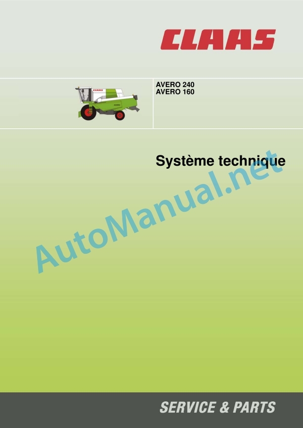
AVERO 240
AVERO 160
Contents
CCN explanation
CCN (CLAAS Component Number)
Electrical standard
Summary table
Hydraulic standard
Overview
CCN (CLAAS Component Number)
CCN Index
Introduction
Safety tips
Safety instructions and risk information
Validity of the notice
Validity of the notice
01 Motor
0150 Engine assembly parts
Start the diesel engine
Measurement value table
Description of the function
0155 Engine controls
Diesel engine monitoring
Measurement value table
Description of the function
Diesel Engine Error Codes – J 1939 / Engine Diagnostics / Component Position
CATERPILLAR C6.6
Error code
03 Chassis
0335 Advance command
Hydrostatic transmission, mechanically controlled
Description of the function
Transmission hydraulic connection diagram
Pump unit, motor unit – hydrostatic transmission
05 Management
0505 Steering
General steering system
Neutral functional diagram
Pointed functional diagram
09 Hydraulic system
0920 Valves
Main valve
Hopper Drain Tube Distribution Block
Mixer variator distribution block
Front tool damping distribution block
Steering distribution block (Orbitrol)
Distribution block, low pressure hydraulic system
Reel drive distribution block
AUTOCONTOUR distribution block / Reverse
0980 Hydraulic connection plan
Vehicle hydraulic system connection diagrams
Connection diagram of the complete hydraulic system, without radiator rotary screen retrofit kit
Connection diagram of the complete hydraulic system, with radiator rotary screen retrofit kit
Control and measure
Front attachment hydraulic system connection diagrams
C370-C490 cutting deck (type 527) – Reel adjustment
Vario V540-V900 cutting deck (type 716) – reel adjustment
Vario cutting deck V540-V1050 (type 716) – rapeseed saw drive
Folding cutting deck 450-540 (type 713)
10 Electrical/electronic system
1010 Central electrical system
Basic main electrical system (ZE base)
Main roof electrical system
Fuse Allocation: Main Roof Electrical System
1012 Modules – Sensors
Module overview
Overview of module positions
Module A008 – Autocontour (CAC)
Allocation of module A008 – Autocontour (CAC)
Module A012 – tachometer relay (SMM)
Module A015 – Engine management module
Allocation of module A015 Engine management module
Module A052 – Multifunction handle (MHM)
Module A060 – hydraulic control (HYD)
Module A101 – dashboard (DBD)
1015 Electrical wiring
Multiple coupling
Multiple front tool coupling
Multiple machine coupling
Description of the function
1080 Electronic connections plan
Introduction connection diagrams
Overview of designations
CLAAS cable marking
Cable colors
Overview of the CAN bus system
Machine electrical connection diagram (SCM) up to machine number 45100050
SCM 01 – multiple coupling
SCM 02 – Electrical voltage supply – start the diesel engine
SCM 03 – Module voltage supply
SCM 04 – Traveling on the road
SCM 05 – Threshing bodies
SCM 06 – electrical voltage supply, sensors
SCM 07 – Ground power supply
SCM 08 – CAN 0 – Vehicle CAN / CAN 1-J1939
SCM 09 – CAN2 CAN front
SCM 10 – Diesel engine speed adjustment – diesel engine control
SCM 11 – Diesel engine monitoring
SCM 12 – couple front tool – reverse front tool
SCM 13 – Raise/lower the front tool
SCM 14 – Fold down the front tool
SCM 15 – Reel speed adjustment
SCM 16 – Reel adjustment
SCM 17 – Table adjustment
SCM 18 – Rapeseed saw
SCM 19 – Circuit blocking valve, hydraulic system monitoring
SCM 20 – RPM monitoring
SCM 21 – Mixer speed adjustment
SCM 22 – Fan speed adjustment
SCM 23 – Machine monitoring
SCM 24 – Flow control
SCM 25 – Swivel hopper drain tube – Hopper drain
SCM 26 – Full hopper indicator – rotating lights
SCM 27 – Brake light
SCM 28 – Reverse gear sound signal
SCM 29 – Air conditioning
SCM 30 – Windshield wiper – Windshield washer system
SCM 31 – Main lighting switching – position lights
SCM 32 – Low beam lights
SCM 33 – Main switching and work lighting
SCM 34 – Hopper working lighting – harvest return – cleaning box
SCM 35 – indicator indicator
SCM 36 – Dashboard lighting
SCM 37 – Cabin equipment
SCM 38 – Female service connectors
SCM 39 – Reserve (options)
SCM 40 – Module overview
SCM 41 – Connector overview
Machine electrical connection diagrams (SCM) from machine number 45000011 / 45100051
SCM 01 – Multiple coupling
SCM 02 – Electrical voltage supply – start the diesel engine
SCM 03 – Module voltage supply
SCM 04 – Traveling on the road
SCM 05 – Threshing bodies
SCM 06 – Sensor voltage supply
SCM 07 – Ground power supply
SCM 08 – CAN0 (Vehicle-CAN) / CAN1 (J1939-CAN)
SCM 09 – CAN2 (front CAN)
SCM 10a – Diesel engine speed adjustment – Diesel engine management (20 km/h)
SCM 10b – Diesel engine speed adjustment – Diesel engine management (25 km/h)
SCM 11- Diesel engine monitoring
SCM 12 – couple front tool – reverse front tool
SCM 13 a – Raise/lower the front tool with AUTO CONTOUR
SCM 13b – Raise/lower the front tool without AUTO CONTOUR
SCM 14 – Fold down the front tool
SCM 15 – Reel speed adjustment
SCM 16 – Reel adjustment
SCM 17 – Table adjustment
SCM 18 – Rapeseed saw
SCM 19 – Circuit blocking valve, hydraulic system monitoring
SCM 20 – RPM monitoring
SCM 21 – Mixer speed adjustment
SCM 22 – Fan speed adjustment
SCM 23 – Machine monitoring
SCM 24 – Flow control
SCM 25 – Swivel hopper drain tube – Hopper drain
SCM 26 – Full hopper indicator – rotating lights
SCM 27 – Brake light
SCM 28 – Reverse gear sound signal
SCM 29 – Air conditioning
SCM 30 – Windshield wiper – Windshield washer system
SCM 31 – Main lighting switching – position lights
SCM 32 – Low beam lights
SCM 33 – Main work lighting switching
SCM 34 – Hopper working lighting – harvest return – cleaning box
SCM 35 – Flashing
SCM 36 – Instrument lighting
SCM 37 – Cabin equipment
SCM 38 – Service sockets
SCM 39 – Reserve (options)
SCM 40 – Module overview
SCM 41 – Connector overview
SCM 44 – Wheel position display
Front tool connection diagrams – soybean cutting apron (type 440)
T440 01 – Multiple coupling
T440 02 – Reel
T440 03 – AUTO CONTOUR
T440 04 – Lighting
T440 05 – Autopilot
Front tool connection diagrams – Standard cutting deck (type 527)
T527 01 – Multiple coupling
T527 02 – Reel
T527 03 – AUTO CONTOUR
T527 04 – Autopilot
Front tool connection diagrams – folding cutting deck (type 713)
T713 01 – Multiple coupling
T713 02 – Reel
T713 03 – Fold down the front tool
T713 04 – AUTO CONTOUR
T713 05 – Lighting
T713 06 – Autopilot
Front tool connection diagrams – Standard cutting deck (type 715)
T715 01 – Multiple coupling
T715 02 – Reel
T715 03 – Rapeseed knife
T715 04 – AUTO CONTOUR
T715 05 – Autopilot
Front tool connection diagrams – VARIO cutting deck (type 716)
T716 00 – Module overview
T716 01 – Multiple coupling
T716 02 – Module voltage supply / CAN bus
T716 03 – Reel
T716 04 – Table adjustment
T716 05 – Rapeseed knife
T716 06 – AUTO CONTOUR
T716 07 – Autopilot
Connector database (chp CLAAS)
Example representation of coding numbers (CHP)
Connector representation (CHP)
12 Cabin – Driving position
1230 Headquarters
Seat contact
Measurement value table
Description of the function
1240 Air conditioning
Air conditioning function
Measurement value table
Description of the function
20 Harvest feeding
2002 Front tool
Raise / Lower the front tool
Measurement value table
Description of the function
Main valve
Front tool on/off
Description of the function
Reverse front tool
Measurement value table
Description of the function
Front tool cushioning
Measurement value table
Description of the function
Front tool damping valve
Accumulation pressure filling instructions
Manual transverse regulation
Measurement value table
Description of the function
AUTOCONTOUR distribution block / Reverse
2010 Cutting deck extension
VARIO – Cutting table adjustment
Measurement value table
Description of how the reel adjustment works
2015 Reel / Equalizer
Raise/lower the reel
Measurement value table
Description of how the reel adjustment works
Reel forward/backward
Measurement value table
Description of how the reel adjustment works
Adjustment of reel speed, automatic reel speed
Measurement value table
Description of how the reel adjustment works
26 Ground guidance
2605 Self-Contour
AUTO CONTOUR (CAC) / CONTOUR
Measurement value table
Adjustment of CAC probe sensors
Description of the function
AUTO CONTOUR distribution block / reverse
Accumulation pressure filling instructions
41 Threshing bodies
4100 Threshing bodies
ON / OFF of the threshers
Measurement value table
Description of the function
4120 Drummer
Mixer speed adjustment
Measurement value table
Description of the function
61 Grain recovery
6120 Emptying the hopper
Hopper emptying
Measurement value table
Function description
Rotate the hopper tube
Measurement value table
Function description
Diagnosis according to error codes
FMI (Failure Mode Indicator) error code
FMI (Failure Mode Indicator) error code
FMI 00 (Signal too large)
FMI 01 (signal too small)
IMF 02 (Implausible signal)
FMI 03 (voltage too high)
FMI 04 (voltage too low)
FMI 05 (current too low)
FMI 06 (current too high)
FMI 07 (mechanical error)
FMI 08 (frequency signal defective)
FMI 09 (communication error)
FMI 10 (signal modification too fast)
FMI 11 (multiple error)
FMI 12 (ECU faulty)
FMI 13 (signal outside calibration range)
FMI 16 (non-existent parameter)
FMI 17 (ECU not responding)
FMI 18 (voltage supply error)
FMI 19 (software conditions not met)
FMI 95 (no signal modification)
FMI 96 (CAN-bus system defective)
IMF 97 (implausible state)
IMF 98 (alarm)
IMF 99 (News)
Error codes
AVERO Error Code List
Overview of error codes
Location of parts
Hydraulic system
Distribution blocks
1000 Oil tank/filter/oil cooler
2000 Pump / Motor
3000 Main hydraulic cylinder
4000 Restrictor / Calibrated Orifice
5000 Pressure accumulator
6000 Valves – mechanical control
7000 Valves – hydraulic control
8000 Couplings / fittings
9000 Measuring points / display instruments
Electrical system
A Terminal / Modules
B Sensors
C Electrical/electronic devices
D Light-emitting diode
E Lighting
G Voltage sources
H Signal device / indicator lights
K Relays
M Motor (electric)
R Potentiometer / resistor
S Switch / Button – cabin control
U Switches – external control
V Electronic components
X Connectors
Y Electromagnetic coil
Z Actual value switches
Main electrical system
Grounding points
John Deere Repair Technical Manual PDF
John Deere Repair Technical Manual PDF
John Deere PowerTech M 10.5 L and 12.5 L Diesel Engines COMPONENT TECHNICAL MANUAL CTM100 10MAY11
John Deere Repair Technical Manual PDF
John Deere 18-Speed PST Repair Manual Component Technical Manual CTM168 10DEC07
John Deere Repair Technical Manual PDF
John Deere Repair Technical Manual PDF
John Deere Parts Catalog PDF
John Deere Tractors 7500 Parts Catalog CPCQ26568 30 Jan 02 Portuguese
John Deere Repair Technical Manual PDF
John Deere Repair Technical Manual PDF
John Deere 16, 18, 20 and 24HP Onan Engines Component Technical Manual CTM2 (19APR90)
John Deere Repair Technical Manual PDF
John Deere Diesel Engines POWERTECH 2.9 L Component Technical Manual CTM126 Spanish


