Claas Axion 850-810 Hexashift (A30) Tractors Operator Manual ES
$50.00
- Model: Axion 850-810 Hexashift (A30) Tractors
- Type Of Manual: Operator Manual
- Language: ES
- Format: PDF(s)
- Size: 170 MB
File List:
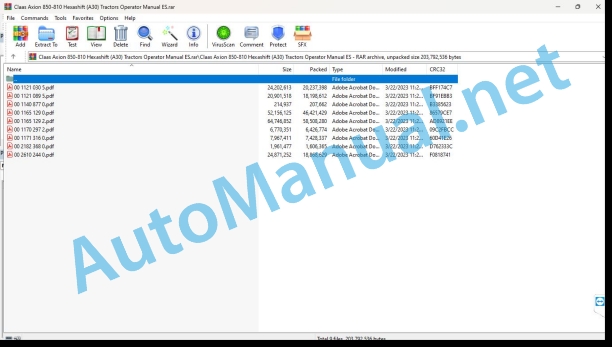
00 1121 030 5.pdf
00 1121 089 5.pdf
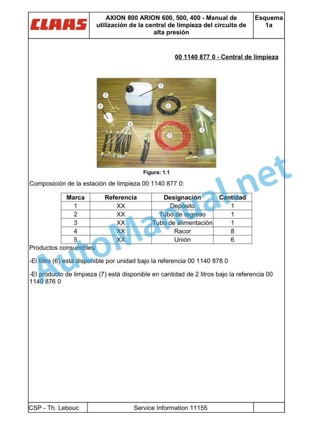
00 1140 877 0.pdf
00 1165 129 0.pdf
00 1165 129 2.pdf
00 1170 297 2.pdf
00 1171 316 0.pdf
00 2182 368 0.pdf
00 2610 244 0.pdf
00 1121 030 5.pdf:
. Information about this user manual
. Validity of the instructions for use
. Chapter symbols
A – Identification – Homologation – Safety
1. Tractor signal plate
2. Tractor power label
3. Engine signal plate
4. Cabin nameplate
5. European regulations
6. Security
6.1. Security instructions
6.1.1. Use according to the purpose
6.1.2. Use not in accordance with assignment
6.1.3. Precautions to be taken before starting up
6.1.4. Tractor status
6.1.5. Adjustment or maintenance work – repairs
6.1.5.1. General rule
6.1.5.2. Placement on lifting arms
6.1.5.3. Electricity
6.1.5.4. Fuel
6.1.5.5. Coolant liquid
6.1.6. Circulation – transport
6.1.7. Tractor use
6.1.7.1. General rule
6.1.7.2. Tractor wheelbase
6.1.7.3. Tool attachment
6.1.7.4. Driving
6.1.7.5. Permanent jobs
6.1.7.6. Work with tools powered by the power take-off
6.1.7.7. Severe applications
6.1.8. Toxic products
6.1.9. Air-conditioning
6.1.10. Cabin
6.1.11. passenger seat
6.1.12. Respect for the environment
6.1.13. Using a front loader
6.1.14. Forestry applications
6.2. Safety stickers with warning pictograms
6.2.1. recommendations
6.2.2. Putting the gearbox in neutral
6.2.3. Front lift
6.2.4. Front tow hook
6.2.5. User manual
6.2.6. passenger seat
6.2.7. Speed limit and child under 13 years old
6.2.8. Air conditioning
6.2.9. PTO 1,000 1/min
6.2.10. hydraulic hoses
6.2.11. External controls
6.2.12. start
6.2.13. Battery
6.2.14. Radar
6.2.15. PTO protection
6.2.16. High pressure cleaner
6.2.17. Accumulator .2.18. FOPS Roof
6.2.19. Wheel nuts
6.2.20. Electrohydraulic distributors
B – Cabin
1. Driving and working environment
1.1. Controls and instruments (cockpit)
1.2. Controls and instruments (dashboard)
1.3. Accommodations and accessories
2. Lighting, signage and security
2.1. Description
2.2. Low beam/high beam and klaxon
23. Work lights and rotating headlight
2.4. Roof light
2.5. Mirrors
3. Start contactor
4. Multifunction elbow support
5. Cabin suspension
5.1. Z-Activ Cabin
5.2. Z Cabin
6. Seats
6.1. driver’s seat
6.2. Passenger seat
7. steering wheel
8. Dashboard
8.1. Description
8.2. Functioning
8.3. Utilization
8.4. Calibration
9. Visualizer
9.1. Cebis Terminal
10. Openers and glass
11. Viewer
12. Heating – ventilation – manual air conditioning
12.1. Description
12.2. Utilization
13. Heating/ventilation automatic air conditioning
13.1. Description
13.2. Utilization
C – ELECTRICITY
1. Features
2. Trailer/tool lighting socket
3. Power socket electrical box
4. Taking the event counter
5. ISO shooting
6. ISOBUS connection
7. Predisposition for the installation of a control box in the cabin
7.1. Fixing the box support
7.2. Cable routing
8. Battery
8.1. battery tray
8.2. battery switch
9. Fuses and relays
9.1. recommendations
9.2. Cab service fuse box
9.3. Upper cabin fuse box
9.4. Primary Service Fuse Box
D – Engine
1. Features
2. Visualizers
2.1. Dashboard
2.2. Cebis Terminal
3. Security
3.1. Functioning
3.2. Cebis Terminal
3.3. Dashboard
3.4. recommendations
4. Engine hood
4.1. Monobloc hood
4.2. Side hoods
5. Engine control
5.1. Engine start
5.1.1. Preliminary operations
5.1.2. Start up
5.1.3. Coolant heater
5.2. Using the accelerator pedal and lever
5.2.1. Functioning
5.2.2. Accelerator pedal
5.2.3. manual throttle
5.2.4. Engine speed memor .4.1. Utilization
5.2.4.2. Adjustment procedure by Cebis
5.2.4.3. Manual adjustment procedure
5.3. Engine stop
6. CLAAS Power Management
7.1. recommendations
7.2. Bleeding air from the injection circuit
E – Transmission
1. Features
2. Forward speeds
3. Indication
3.1. Cebis Terminal
3.2. Dashboard
4. Security
4.1. Neutral inverter
4.1.1. Utilization
4.1.2. Functioning
4.2. Neutral transmission
4.2.1. Utilization
4.2.2. Functioning
4.3. Protection of mechanical organs
4.3.1. Functioning
4.3.2. Dashboard
4.3.3. Cebis Terminal
5. Setting in motion
5.1. Clutch
5.1.1. recommendations
5.1.2. Clutch pedal
5.1.3. reverse lever
5.2. Selection of feed direction
5.2.1. Utilization
5.2.2. recommendations
5.3. Inverter progressivity adjustment
5.3.1. Utilization
5.3.2. Adjustment
5.4. Engaging/disengaging front/rear speeds
5.4.1. Utilization
5.4.2. Adjustment
5.4.3. Functioning
6. Manual gear operation
6.1. Starting ratio
6.1.1. Functioning
6.1.2. Adjustment
6.2. Work mode
6.3. Transport mode
7. Automatic gear change
7.1. Skip shift
7.1.1. Utilization
7.1.2. Functioning
7.2. Automatic speed adaptation (Speed Matching)
7.2.1. Utilization
7.2.2. Functioning
7.3. Maneuvering ratio
7.3.1. Utilization
7.3.2. Adjustment
7.3.3. Functioning
7.4. Hexactiv
7.4.1. Utilization
7.4.2. Functioning
7.4.3. Selection of the automation regime
7.4.4. Demarcation of automation
7.4.4.1. Utilization
7.4.4.2. Functioning
7.4.5. Starting ratio in Hexactiv and transport mode
7.4.5.1. Utilization
7.4.5.2. Functioning
7.4.5.3. Adjustment
8. Relationship Management
Function 9. Super-slow range
9.1. Utilization
9.2. Functioning
rear axle
1. Features
2. Indication
3. Protection of mechanical organs
3.1. Functioning
3.2. Dashboard
3.3. Cebis Terminal
4. Locking differentials
4.1. recommendations
4.2. Functioning
4.3. Automatic mode
4.3.1. Utilization
4.3.2. Functioning
4.4. Permanent mode
4.4.1. Utilization
4.4.2. Functioning
5. Brakes
5.1. Service brakes
5.2. Parking brake (auxiliary and parking brake)
5.2.1. Obligations
5.2.2. Hand brake
5.2.3. automatic brake
5.2.3.1. Utilization
5.2.3.2. Functioning
6. Trailer braking
6.1. Hydraulic brake
6.2. pneumatic brake
F – Front axle
1. Features
2. Protection of mechanical organs
2.1. Functioning
2.2. Dashboard
23. Cebis Terminal
3. Front axle gear
3.1. Functioning
3.2. Automatic mode
3.2.1. Utilization
3.2.2. Functioning
3.3. Permanent mode
3.3.1. Utilization
3.3.2. Functioning
4. Locking differentials
4.1. recommendations
4.2. Functioning
4.3. Automatic mode
4.3.1. Utilization
4.3.2. Functioning
4.4. Permanent mode
4.4.1. Utilization
4.4.2. Functioning
5. Suspended front axle
5.1. Functioning
5.2. Fixed mode
5.2.1. Utilization
5.2.2. Functioning
5.3. Automatic mode
5.3.1. Utilization
5.3.2. Functioning
G – Rear equipment
Hydraulic
1. Features
2. Auxiliary distributors
2.1. Association of rear controls/pressure taps
2.2. pressure taps
2.2.1. recommendations
2.2.2. Utilization
2.2.3. Free return to the warehouse
2.2.4. Oil recovery button
23. Controls
2.4. Security
2.4.1. Protection of mechanical organs
2.4.2. Cebis Terminal
2.5. Start up
2.5.1. Utilization
2.5.2. Display on the Cebis terminal
2.5.3. Functioning
2.6. Online controls
2.7. Cross control
2.8. External controls
2.9. Management of electrohydraulic distributors
2.9.1. Utilization
2.9.2. Visualizer
2.9.3. Maximum flow rate of a pressure tap
2.9.4. Hydraulic timer
2.9.5. Activation of the distributor on the exterior controls
2.9.6. Locking the electrohydraulic distributors
3. Power beyond
3.1. Description
3.2. Utilization
3.3. Functioning
4. Permanent job
rear lift
1. Features
2. Controls
3. Visualizer
4. Security
4.1. Protection of mechanical organs
4.2. safety pilot
4.3. Cebis Terminal
4.4. Transportation security
5. Lift start-up
6. Mode selection
7. Position control
8. Effort control
9. High cap
10. Download speed
11. Transport shock absorber
12. Active skating management
12.1. Utilization
12.2. Adjustment
12.3. Functioning
13. External controls
13.1. Utilization
13.2. Functioning
rear power take off
1. Features
2. Recommendations
3. Controls
4. Indication
5. PTO speed selection
6. Usage
7. External controls
8. Operation
9. PTO automation
9.1. Utilization
9.2. manual adjustment
9.3. Adjustment by Cebis terminal
10. PTO ferrule
11. Tool attachment on the power take-off
12. Permanent job
rear hitch
1. Features
2. Recommendations
3. Fixing mechanisms
4. Upper connecting rod
4.1. Mechanical upper connecting rod
4.2. Hydraulic upper connecting rod
5. Automatic hooks
6. Stabilizers
6.1. Utilization
6.2. Mechanical stabilizers
6.3. Self-Locking Stabilizers
7. Hitch Bolts
8. Bar with ball
9. Swing bar
10. Pickup hitch
H – Front equipment
Hydraulic
1. Features
2. Pressure taps
2.1. recommendations
2.2. UTILIZATION
23. Free return to the warehouse
3. Security
3.1. Protection of mechanical organs
3.2. Cebis Terminal
4. Distributor controlled front pressure intakes 3
4.1. Description
4.2. Controls
4.3. Preliminary operations
4.4. UTILIZATION
5. Distributor controlled front pressure intakes 7
5.1. Description
5.2. Controls
5.3. Preliminary operations
5.4. UTILIZATION
6. Front pressure intakes controlled by distributors 7 and 8
6.1. Description
6.2. Controls
6.3. Preliminary operations
6.4. UTILIZATION
7. Management of electrohydraulic distributors
Front lift
1. Features
2. Distributor Controlled Front Lift 1
2.1. Controls
2.2. Security
2.2.1. Private lockers
2.2.2. Protection of mechanical organs
2.2.3. Cebis Terminal
2.2.4. Transportation security
23. Preliminary operations
2.4. UTILIZATION
2.5. External controls
3. Distributor Controlled Front Lift 6
3.1. Controls
3.2. Security
3.2.1. Private lockers
3.2.2. Protection of mechanical organs
3.2.3. Cebis Terminal
3.2.4. Transportation security
3.3. Preliminary operations
3.4. UTILIZATION
3.5. External controls
4. Transport shock absorber
5. Position control
5.1. Indication
5.2. Description of settings
5.3. Activation of position control
5.4. High stop adjustment
5.5. Low stop adjustment
5.6. Ascent speed adjustment
5.7. Descent speed adjustment
5.8. Using position control
6. 3-point hitch
6.1. lower cranks
6.2. Upper connecting rod
6.3. Hitching and unhitching the implement
front power take off
1. Features
2. Indication
3. Recommendations
4. Front PTO interlock
5. Front PTO stop
Front loader
1. Assembly of an adaptation structure for a front loader
I – Cebis Terminal
Using the Cebis terminal
1. Description
2. Operation
4. Multifunction display
4.1. Utilization
4.2. Work screen
4.3. Road screen
5. Direct Access
5.1. Utilization
5.2. Functioning
6. Operating anomalies
6.1. Functioning
6.2. Alarms
6.2.1. Description
6.2.2. Utilization
6.2.3. Functioning
6.3. Warning
6.3.1. Description
6.3.2. Utilization
6.3.3. Functioning
6.4. Information
6.4.1. Description
6.4.2. Utilization
6.4.3. Functioning
6.5. Icon
6.5.1. Description
6.5.2. Utilization
6.5.3. Functioning
7.1. Main menu
7.2. Transmission
7.3. Elevation
7.4. Hydraulic
7.5. On-board computer
7.6. CLAAS Sequence Management
7.7. Previewing a CLAAS Sequence Management sequence in real time
On-board computer
1. Usage
2. General features
2.1. Utilization
2.2. Programmable window parameterization
23. Resetting the counters to zero
3. Plot management
3.1. Utilization
3.2. Start/stop of counters
3.2.1. Procedure through Cebis
3.2.2. Manual procedure
3.3. Plot Management Editor
3.3.1. Utilization
3.3.2. Selecting a plot
3.3.3. Resetting the counters of a plot
4. Tool parameterization
4.1. Working width
4.2. counting mode
4.3. Selection of theoretical or real speed
4.4. Tool management
4.4.1. Utilization
4.4.2. Safeguarding the parameters of the tool in use
4.4.3. Registering a new tool
4.4.4. Loading a tool
4.4.5. Loading a CLAAS tool
4.4.6. Changing the name of a tool
4.4.7. Deleting a tool
5. Maintenance
5.1. Maintenance counter
5.1.1. Utilization
5.1.2. Resetting the counters to zero
5.2. List of active anomalies
5.3. Transmission oil temperature
6. Function contactors F1, F2, F3 and F4
6.1. Utilization
6.2. Adjustment
6.2.1. Description
6.2.2. Count
6.2.3. CLAAS Sequence Management
6.2.4. ISOBUS
6.2.5. Front loader
6.2.6. Electrohydraulic distributor 8
7. Cebis
7.1. Brightness
7.1.1. Automatic brightness adjustment
7.1.2. Manual brightness adjustment
7.2. Languages and units
7.2.1. Language
7.2.2. Units
7.3. Date and Time
CLAAS Sequence Management
1. Usage
2. Operation
3. Controls
3.1. Description
4. Security
4.1. Protection of mechanical organs
5. Launching a sequence
5.1. Utilization
5.2. Functioning
6. Recording a sequence
7. Interrupting a sequence
7.1. Momentary interruption of a sequence in progress
7.2. Definitive interruption of a momentarily interrupted sequence
7.3. Permanent interruption of a sequence in progress
7.4. Interruption of ongoing actions
7.5. Emergency stop
8. Viewing a sequence
8.1. Display in info mode
8.1.1. Utilization
8.1.2. Description
8.2. Viewing in real time
8.2.tilization
8.2.2. Description
9. Modifying a sequence
9.1. Utilization
9.2. Modifying a step in a sequence
9.3. Add a stage in a sequence
9.4. Deleting a step in a sequence
9.5. Selecting the recording mode of a sequence
J – Wheels and tires
1. Tires
1.1. recommendations
1.2. inflation pressure
1.2.1. Characteristics
1.2.2. recommendations
1.3. Load index
1.4. speed code
2. Paths
2.1. Commissioning
2.2. front tracks
2.2.1. Front bridge
2.2.2. Front Track Tables
2.2.3. Front axle swing stops
23. rear tracks
2.3.1. rear axle
2.3.2. Rear track boards
2.3.3. Track with smooth tree rear bridge
2.4. Tire combinations
3. WHEELS
3.1. Generalities
3.2. twin wheels
3.2.1. Disc wheel axle and 2.5 meter smooth wheel axle
3.2.1.1. Characteristics
3.2.1.2. Description
3.2.1.3. Mounting the coupled wheels
3.2.1.4. Front Pairing
3.2.1.5. rear combination
3.2.2. 3 meter smooth wheel axle
3.2.2.1. Description
3.2.2.2. Utilization
K – Features
1. Dimensions
2. Weight
3. Loading capacities
4. Maximum permissible towable masses
5. Capacities
6. Weighted
6.1. Ballasts available
6.2. Tractor balancing
7. Cabin comfort
7.1. Sound level
7.2. vibration level
L – Maintenance
1. Recommendations
2. Trailer
3. Transportation
4. Using a jack
5. Changing a wheel
6. Tractor loading and stowage
7. Parking
8. Disablement and destruction
9. Periodicities
9.1. Summary table
9.2. Operations
9.2.1. Operation #1
9.2.2. Operation #2
9.2.3. Operation #3
9.2.4. Operation #4
9.2.5. Operation #5
9.2.6. Operation #6
9.2.7. Operation #7
9.2.8. Operation #8
9.2.9. Operation #9
9.2.10. Operation #10
9.2.11. Operation #11
9.2.12. Operation #12
9.2.13. Operation #13
9.2.14. Operation #14
9.2.15. Operation #15
9.2.16. Operation #16
9.2.17. Operation #17
9.2.18. Operation #18
9.2.19. Operation #19
9.2.20. Operation #20
9.2.21. Operation #21
9.2.22. Operation #22
9.2.23. Operation #23
9.2.24. Operation #24
9.2.25. Operation #25
9.2.26. Operation #26
9.2.27. Operation #27
9.2.28. Operation #28
9.2.29. Operation #29
9.2.30. Operation #30
9.2.31. Operation #31
9.2.32. Operation #32
9.2.33. Operation #33
9.2.34. Operation #34
9.2.35. Operation #35
9.2.36. Operation #36
9.2.37. Operation #37
9.2.38. Operation #38
9.2.39. Operation #39
9.2.40. Operation #40
9.2.41. Operation #41
9.2.42. Operation #42
9.2.43. Operation #43
9.2.44. Operation #44
9.2.45. Operation #45
9.2.46. Operation #46
9.2.47. Operation #47
9.2.48. Operation #48
9.2.49. Operation #49
9.2.50. Operation #50
9.2.51. Operation #51
9.2.52. Operation #52
9.2.53. Operation #53
9.2.54. Operation #54
9.2.55. Operation #55
9.2.56. Operation #56
9.2.57. Operation #57
9.2.58. Operation #58
9.2.59. Operation #59
9.2.60. Operation No. 60
9.2.61. Operation #61
9.2.62. Operation No. 62
9.2.63. Operation No. 63
9.2.64. Operation #64
9.2.65. Operation No. 65
9.2.66. Operation #66
10. Bleeding the air from the injection circuit
11. Maintenance operations logbook
M – Mandatory warranty operations
1. MANDATORY OPERATIONS CARRIED OUT WITHIN THE FRAMEWORK OF THE CONTRACTUAL WARRANTY
1.1. Inspection before delivery
1.2. Customer delivery
1.3. MAINTENANCE OPERATIONS TO BE CARRIED OUT
1.4. Mandatory visits
1.4.1. Mandatory inspection after the first 100 hours
1.4.2. Mandatory inspection after the first 500 hours
Alphabetical index
00 1121 089 5.pdf:
. Information about this user manual
. Validity of instructions
. Chapter symbols
A – Identification – Homologation – Safety
1. Tractor signal plate
2. Tractor power label
3. Engine signal plate
4. Cabin nameplate
5. European regulations
6. Security
6.1. Security instructions
6.1.1. Use according to the purpose
6.1.2. Use not in accordance with assignment
6.1.3. Precautions to be taken before starting up
6.1.4. Tractor status
6.1.5. Adjustment or maintenance work – repairs
6.1.5.1. General rule
6.1.5.2. Placement on lifting arms
6.1.5.3. Electricity
6.1.5.4. Fuel
6.1.5.5. Coolant liquid
6.1.6. Circulation – transport
6.1.7. Tractor use
6.1.7.1. General rule
6.1.7.2. Tractor wheelbase
6.1.7.3. Tool attachment
6.1.7.4. Driving
6.1.7.5. Permanent jobs
6.1.7.6. Work with tools powered by the power take-off
6.1.7.7. Severe applications
6.1.8. Toxic products
6.1.9. Air-conditioning
6.1.10. Cabin
6.1.11. passenger seat
6.1.12. Respect for the environment
6.1.13. Using a front loader
6.1.14. Forestry applications
6.2. Safety stickers with warning pictograms
6.2.1. recommendations
6.2.2. Putting the gearbox in neutral
6.2.3. Front lift
6.2.4. Front tow hook
6.2.5. User manual
6.2.6. passenger seat
6.2.7. Speed limit and child under 13 years old
6.2.8. Air conditioning
6.2.9. PTO 1,000 1/min
6.2.10. hydraulic hoses
6.2.11. External controls
6.2.12. start
6.2.13. Battery
6.2.14. Radar
6.2.15. PTO protection
6.2.16. High pressure cleaner
6.2.17. Accumulators
6.2.18. FOPS Roof
6.2.19. Wheel nuts
6.2.20. Electrohydraulic distributors
B – Cabin
1. Driving and working environment
1.1. Controls and instruments (cockpit)
1.2. Controls and instruments (dashboard)
3. Accommodations and accessories
2. Lighting, signage and security
2.1. Descriptio 2.2. Low beam/high beam and klaxon
23. Work lights and rotating headlight
2.4. Roof light
2.5. Mirrors
3. Start contactor
4. Multifunction elbow support
5. Seats
5.1. Driver’s seat
5.2. passenger seat
6. steering wheel
7. Dashboard
7.1. Description
7.2. Functioning
7.3. Utilization
7.4. Calibration
8. Visualizer
8.1. Transmission display
9. Openers and glass
10. Viewer
11. Heating – ventilation – manual air conditioning
11.1. Description
11.2. Utilization
12. Heating/ventilation automatic air conditioning
12.1. Description
12.2. Utilization
13. Cabin suspension
C – ELECTRICITY
1. Features
2. Trailer/tool lighting socket
3. Power socket electrical box
4. Taking the event counter
5. ISO shooting
6. ISOBUS connection
7. Predisposition for the installation of a control box in the cabin
7.1. Fixing the box support
7.able routing
8. Battery
8.1. battery tray
8.2. battery switch
9. Fuses and relays 9.1. recommendations
9.2. Cab service fuse box
9.3. Upper cabin fuse box
9.4. Primary Service Fuse Box
D – Engine
1. Features
2. Visualizers
2.1. Dashboard
3. Security
3.1. Functioning
3.2. Dashboard
3.3. recommendations
4. Engine hood
4.1. Monobloc hood
4.2. Side hoods
5. Engine control
5.1. Engine start
5.1.1. Preliminary operations
5.1.2. Start up
5.1.3. Coolant heater
5.2. Using the accelerator pedal and lever
5.2.1. Functioning
5.2.2. Accelerator pedal
5.2.3. manual throttle
5.2.4. Engine speed memory
5.2.4.1. Utilization
5.2.4.2. Adjustment
5.3. Engine stop
6. CLAAS Power Management
7.1. recommendations
7.2. Bleeding air from the injection circuit
E – Transmission
1. Features
2. Forward speeds
3. Indication
3.1. Transmission display
3.2. Dashboard
4. Security
4.1. Neutral inverter
4.1.1. Utilization
4.1.2. Functioning
4.2. Neutral transmission
4.2.1. Utilization
4.2.2. Functioning
4.3. Protection of mechanical organs
4.3.1. Functioning
4.3.2. Dashboard
4.3.3. Transmission display
5. Setting in motion
5.1. Transmission display
5.2. Clutch
5.2.1. recommendations
5.2.2. Clutch pedal
5.2.3. reverse lever
5.3. Selection of feed direction
5.3.1. Utilization
5.3.2. recommendations
5.4. Inverter progressivity adjustment
5.4.1. Utilization
5.4.2. Adjustment
5.5. Engaging/disengaging front/rear speeds
5.5.1. Utilization
5.5.2. Adjustment
5.5.3. Functioning
6. Manual gear operation
6.1. Starting ratio
6.1.1. Functioning
6.1.2. Adjustment
6.2. Work mode
6.3. Transport mode
7. Automatic gear change
7.1. Skip shift
7.1.1. Utilization
7.1.2. Functioning
7.2. Automatic speed adaptation (Speed unching)
7.2.1. Utilization
7.2.2. Functioning
7.3. Maneuvering ratio
7.3.1. Utilization
7.3.2. Adjustment
7.3.3. Functioning
7.4. Hexactiv
7.4.1. Utilization
7.4.2. Functioning
7.4.3. Selection of the automation regime
7.4.4. Demarcation of automation
7.4.4.1. Utilization
7.4.4.2. Functioning
7.4.5. Starting ratio in Hexactiv and transport mode
7.4.5.1. Utilization
7.4.5.2. Functioning
7.4.5.3. Adjustment
8. Relationship Management
8.1. Functioning
8.2. Transmission display
9. Super-slow range
9.1. Utilization
9.2. Functioning
rear axle
1. Features
2. Protection of mechanical organs
2.1. Functioning
2.2. Dashboard
23. Transmission display
3. Locking differentials
3.1. recommendations
3.2. Function 3.3. Automatic mode
3.3.1. Utilization
3.3.2. Functioning
3.4. Permanent mode
3.4.1. Utilization
3.4.2. Functioning
4. Brakes
4.1. Service brakes
4.2. Parking brake (auxiliary and parking brake)
4.2.1. Obligations
4.2.2. Hand brake
4.2.3. automatic brake
4.2.3.1. Utilization
4.2.3.2. Functioning
5. Trailer braking
5.1. Hydraulic brake
5.2. pneumatic brake
F – Front axle
1. Features
2. Protection of mechanical organs
2.1. Functioning
2.2. Dashboard
3. Front axle gear
3.1. Functioning
3.2. Automatic mode
3.2.1. Utilization
3.2.2. Functioning
3.3. Permanent mode
3.3.1. Utilization
3.3.2. Functioning
4. Locking differentials
4.1. recommendations
4.2. Functioning
4.3. Automatic mode
4.3.1. Utilization
4.3.2. Functioning
4.4. Permanent mode
4.4.1. Utilization
4.4.2. Functioning
5. Suspended front axle
5.1. Functioning
5.2. Fixed mode
5.2.1. Utilization
5.2.2. Functioning
5.3. Automatic mode
5.3.1. Utilization
5.3.2. Functioning
G – Rear equipment
Hydraulic
1. Features
2. Auxiliary distributors
2.1. Association of rear controls/pressure taps
2.2. pressure taps
2.2.1. recommendations
2.2.2. Utilization
2.2.3. Free return to the warehouse
2.2.4. Oil recovery button
23. Controls
2.4. Control levers
2.5. Adjustment of the flow of the distributors with mechanical control
3. Power Beyond
3.1. Description
3.2. Utilization
3.3. Functioning
4. Permanent job
4.1. Obligations
rear lift
1. Features
2. Controls
3. Security
3.1. Protection of mechanical organs
3.2. safety pilot
3.3. Transportation security
4. Lift start-up
5. Mode selection
6. Position control
7. Effort control
8. High cap
9. Download speed
10. Transport shock absorber
11. Active skating management
11.1. Utilization
11.2. Adjustment
11.3. Functioning
12. External controls
12.1. Utilization
12.2. Functioning
rear power take off
1. Features
2. Recommendations
3. Controls
4. Indication
5. PTO speed selection
6. Usage
7. External controls
8. Operation
9. PTO automation
9.1. Utilization
9.2. Adjustment
10. PTO ferrule
11. Tool attachment on the power take-off
12. Permanent job
12.1. Obligations
rear hitch
1. Features
2. Recommendations
3. Fixing mechanisms
4. Upper connecting rod
4.1. Mechanical upper connecting rod
4.2. Hydraulic upper connecting rod
5. Automatic hooks
6. Stabilizers
6.1. Utilization
6.2. Mechanical stabilizers
6.3. Self-Locking Stabilizers
7. Hitch Bolts
8. Bar with ball
9. Swing bar
10. Pickup hitch
H – Front equipment
Hydraulic
1. Features
2. Front pressure intakes controlled by distributor 3
2.1. Association of front pressure controls/intakes
2.2. pressure taps
2.2.1. recommendations
2.2.2. UTILIZATION
2.2.3. Free return to the warehouse
23. UTILIZATION
2.4. Flow adjustment
3. Distributor controlled front pressure intakes 7
3.1. Association of front pressure controls/intakes
3.2. pressure taps
3.2.1. recommendations
3.2.2. UTILIZATION
3.2.3. Free return to the warehouse
3.3. Security
3.3.1. Protection of mechanical organs
3.3.2. CLAAS Information System Terminal
3.4. Controls
3.5. Preliminary operations
3.6. UTILIZATION
3.7. Management of electrohydraulic distributors
3.7.1. Description
3.7.2. Maximum flow rate of a white pressure tap
3.7.3. Maximum flow rate of a black pressure tap
3.7.4. Hydraulic timer
Front lift
1. Features
2. Distributor Controlled Front Lift 1
2.1. Controls
2.2. Security
2.2.1. Private lockers
2.2.2. Transportation security
23. Preliminary operations
2.4. UTILIZATION
3. Distributor Controlled Front Lift 6
3.1. Controls
3.2. Security
3.2.1. Private lockers
3.2.2. Protection of mechanical organs
3.2.3. CLAAS Information System Terminal
3.2.4. Transportation security
3.3. Preliminary operations
3.4. UTILIZATION
3.5. External controls
4. Transport shock absorber
5. 3-point hitch
5.1. lower cranks
5.2. Upper connecting rod
5.3. Hitching and unhitching the implement
front power take off
1. Features
2. Indication
3. Recommendations
4. Front PTO interlock
5. Front PTO stop
Front loader
1. Assembly of an adaptation structure for a front loader
I – CLAAS Information System
1. Description
2.1. Functioning
2.2. Main menu
23. Hydraulic circuit menu
2.4. On-board computer menu
2.5. Transmission Menu
2.6. Consumption menu
2.7. Maintenance menu
2.8. Settings menu
J – Wheels and tires
1. Tires
1.1. recommendations
1.2. inflation pressure
1.2.1. Characteristics
1.2.2. recommendations
1.3. Load index
1.4. speed code
2. Paths
2.1. Commissioning
2.2. front tracks
2.2.1. Front bridge
2.2.2. Front Track Tables
2.2.3. Front axle swing stops
23. rear tracks
2.3.1. rear axle
2.3.2. Rear track boards
2.3.3. Track with smooth tree rear bridge
2.4. Tire combinations
3. WHEELS
3.1. Generalities
3.2. twin wheels
3.2.1. Disc wheel axle and 2.5 meter smooth wheel axle
3.2.1.1. Characteristics
3.2.1.2. Description
3.2.1.3. Mounting the coupled wheels
3.2.1.4. Front Pairing
3.2.1.5. rear combination
3.2.2. 3 meter smooth wheel axle
3.2.2.1. Description
3.2.2.2. Utilization
K – Features
1. Dimensions
2. Weight
3. Loading capacities
4. Maximum permissible towable masses
5. Capacities
6. Weighted
6.1. Ballasts available
6.2. Tractor balancing
7. Cabin comfort
7.1. Sound level
7.2. vibration level
L – Maintenance
1. Recommendations
2. Trailer
3. Transportation
4. Using a jack
5. Changing a wheel
6. Tractor loading and stowage
7. Parking
8. Disablement and destruction
9. Periodicities
9.1. Summary table
9.2. Operations
9.2.1. Operation #1
9.2.2. Operation #2
9.2.3. Operation #3
9.2.4. Operation #4
9.2.5. Operation #5
9.2.6. Operation #6
9.2.7. Operation #7
9.2.8. Operation #8
9.2.9. Operation #9
9.2.10. Operation #10
9.2.11. Operation #11
9.2.12. Operation #12
9.2.13. Operation #13
9.2.14. Operation #14
9.2.15. Operation #15
9.2.16. Operation #16
9.2.17. Operation #17
9.2.18. Operation #18
John Deere Repair Technical Manual PDF
John Deere Repair Technical Manual PDF
John Deere Repair Technical Manual PDF
John Deere Diesel Engines PowerTech 4.5L and 6.8L – Motor Base Technical Manual 07MAY08 Portuguese
John Deere Repair Technical Manual PDF
John Deere Repair Technical Manual PDF
John Deere 16, 18, 20 and 24HP Onan Engines Component Technical Manual CTM2 (19APR90)
John Deere Parts Catalog PDF
John Deere Tractors 7500 Parts Catalog CPCQ26568 30 Jan 02 Portuguese
John Deere Repair Technical Manual PDF
John Deere Transmission Control Unit Component Technical Manual CTM157 15JUL05
John Deere Repair Technical Manual PDF
John Deere Repair Technical Manual PDF
John Deere Application List Component Technical Manual CTM106819 24AUG20
John Deere Repair Technical Manual PDF

