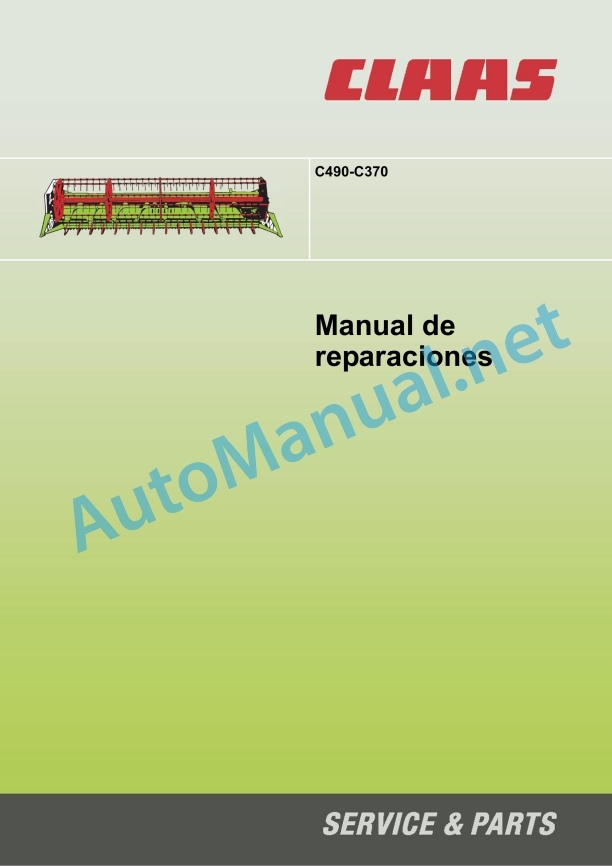
Claas C490-C300 Lexion Tucano (527) Combines Repair Manual ES
$100.00
- Model: C490-C300 Lexion Tucano (527) Combines
- Type Of Manual: Repair Manual
- Language: ES
- Format: PDF(s)
- Size: 8.7 MB
File List:
00 0290 397 0.pdf
00 0290 397 0.pdf:
Introduction
General indications
Manual handling
Manual validity
General repair instructions
Technical data
Cause of the fault
Replacement parts
Welding work
Tensioning steel roller chains
Tapered ring joints
Joints with head key
Self-locking screws with microencapsulated glue
Liquid screw insurance
Bearings with eccentric ring
Bearings with tensioner sleeve
Threaded joints with adjusting ring in hydraulic pipes
Threaded joints with progressive ring in hydraulic pipes
Threaded joints with sealing cone in hydraulic pipes
Hydraulic hoses
The repair is quick and correct, when the following is taken into account
Tightening torques
Tightening torques for metric regulation thread
Tightening torques for metric fine thread
Tightening torques for hydraulic screw connections with adjusting ring DIN 3861
Tightening torques for hydraulic screw connections and air conditioning screw connections with conical seal and toroidal seal DIN 3865
Tightening torques for hydraulic threaded fittings DIN 3901
Tightening torques for addressable hydraulic threaded fittings ISO 6149-2 / ISO 11926-2 (3)
Tightening torques for tilting threaded joints
Tightening torques for hollow screws DIN 7643
Tightening torques for brake line joints
Tightening torques for helical thread clamps
Technical data
Lubricants
CCN Statements
CCN (CLAAS Component Number = CLAAS component number)
General indications
Electrical installation regulations
Hydraulic installation regulations
Security measures
General indications
Especially important
Warning and danger signs
General prescriptions for safety and accident prevention
Headers and trailers
Adjustment and maintenance work
Risk of accident due to hydraulic fluid
First aid measures
Raise the machine on blocks
Put the machine out of service
02 Gears / coupling / cardan shaft
02 60 Cardan shaft
Disassemble and dismantle the cardan shaft
Cardan shaft summary
Assemble and mount the cardan shaft
08 Drives
08 00 Drive diagram
Drive scheme
08 14 Intermediate shaft
Remove the intermediate shaft
Intermediate shaft summary
Install the intermediate shaft
09 Hydraulic installation
09 15 Hydraulic pipes
Summary of Multi-Head Coupling (8011)
09 20 Valves
Reel Regulation Valve Block Summary
09 20 Special valve tool
Remove the valve element
Unscrew the iron core
Remove the seal ring
20 Reception of the harvest
20 15 Windlass
Disassemble the reel
Assemble the windlass
Remove the reel suspension
Reel Suspension Summary
Assemble the windlass suspension
Reel RPM Sensor Summary (B017)
Reel height adjustment sensor summary (B039)
Remove the left support arm from the reel
Assemble the left reel support arm
Remove the right support arm from the reel
Assemble the right support arm of the reel
Remove the right star from the reel
Summary of the right pinwheel star
Assemble the right star of the reel
Remove the central star from the reel
Summary of the central pinwheel star
Assemble the central star of the windlass
Remove the left star from the reel
Summary of the left pinwheel star
Install the left star of the reel
Dismantle the command star
Command Star Summary
Assemble the command star
Remove the spike tube from the reel
Install the reel barbed tube
Remove the reel drive
Summary of the reel chain drive (K9)
Assemble the reel drive
Summary of Chain Drive Sprocket (K9)
Summary of chain driven sprocket (K9)
Dismantle the hydraulic cylinder of the horizontal adjustment of the reel (3016)
Summary of the hydraulic cylinder for horizontal reel regulation (3016)
Assemble the hydraulic cylinder of the horizontal regulation of the reel (3016)
Dismantle the hydraulic cylinder of the left reel height adjustment (3015)
Summary of the hydraulic cylinder of the left reel height adjustment (3015)
Assemble the hydraulic cylinder of the left reel height adjustment (3015)
Dismantle the hydraulic cylinder of the right reel height adjustment (3014)
Summary of the hydraulic cylinder of the right adjustment of the height of the reel (3014)
Assemble the hydraulic cylinder of the right reel height adjustment (3014)
Remove the hydraulic motor from the reel drive (2012)
Reel Drive Hydraulic Motor Summary (2012)
Assemble the hydraulic motor of the reel drive (2012)
21 Power supply unit
21 40 Feed drum
Remove the feed drum
Install the feed drum
Remove the left feed drum suspension
Summary of Left Feed Drum Suspension
Install the left feed drum suspension
Remove the right feed drum suspension
Install the right feed drum suspension
Remove the adjusting shaft
Adjustment axis summary
Install the adjusting shaft
Dismantle the control shaft
Command tree summary
Install the control shaft
Summary chain (K6) feed drum drive
Remove the chain driven sprocket (K6) with friction clutch
Overview of chain driven sprocket (K6) with friction clutch
Install the chain driven sprocket (K6) with friction clutch
21 40 Feed drum special tool
Removing/installing the feed drum suspension
Remove/install chain driven sprocket (K6) with friction clutch
23 Harvesting device
23 05 Cutter bar
Disassemble and dismantle the oscillating gear
Swing Gear Summary
Assemble and assemble the oscillating gear
Blade drive summary, belt (R1)
Tensioner pulley, belt (R1) summary
Deflection pulley, belt (R1), summary
Remove the belt driven pulley (R1)
Summary of belt driven pulley (R1)
Install the belt driven pulley (R1)
21 23 Reaper device special tool
Disassemble/assemble oscillating gear
Install the belt deflection pulley (R1)
26 Adaptation to the soil
26 05 AUTO CONTOUR
AUTO CONTOUR Probe Sensor Summary (B003 / B004)
80 Pieces for assembly / machine body
80 10 Lock
Remove head lock
Head Lock Summary
Install the head lock
CCN (CLAAS Component Number = CLAAS component number)
Alphabetical index
John Deere Repair Technical Manual PDF
John Deere PowerTech M 10.5 L and 12.5 L Diesel Engines COMPONENT TECHNICAL MANUAL CTM100 10MAY11
John Deere Repair Technical Manual PDF
John Deere Diesel Engines POWERTECH 2.9 L Component Technical Manual CTM126 Spanish
John Deere Repair Technical Manual PDF
John Deere Repair Technical Manual PDF
John Deere Transmission Control Unit Component Technical Manual CTM157 15JUL05
John Deere Repair Technical Manual PDF
John Deere Repair Technical Manual PDF
John Deere Repair Technical Manual PDF
John Deere Repair Technical Manual PDF
John Deere 18-Speed PST Repair Manual Component Technical Manual CTM168 10DEC07
John Deere Repair Technical Manual PDF


