Claas Celtis 456-426 (A24) Tractors Operator Manual EN
$50.00
- Model: Celtis 456-426 (A24) Tractors
- Type Of Manual: Operator Manual
- Language: EN
- Format: PDF(s)
- Size: 25.1 MB
File List:
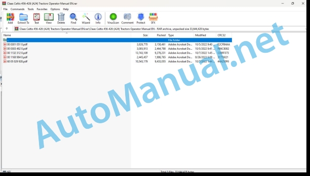
00 0301 051 0.pdf
00 0303 482 0.pdf
00 1132 312 0.pdf
00 1169 984 0.pdf
60 05 029 928.pdf
00 0301 051 0.pdf:
PROFI CAM 3
Table of contents
1 Introduction
1.1 Notes on the manual
1.1.1 Validity of manual
1.1.2 Information about this Operator’s Manual
1.1.3 Symbols and notes
1.1.4 Optional equipment
1.1.5 Qualified specialist workshop
1.1.6 Maintenance information
1.1.7 Warranty notes
1.1.8 Spare parts and technical questions
1.2 Intended use
1.2.1 Intended use
1.2.2 Reasonably foreseeable misuse
2 Safety
2.1 Identifying warnings
2.1.1 Hazard signs
2.1.2 Signal word
2.2 Safety rules
2.2.1 Meaning of Operator’s Manual
2.2.2 Observing safety decals and warnings
2.2.3 Optional equipment and spare parts
3 Product description
3.1 Overview and method of operation
3.1.1 How the PROFI CAM works
3.2 Identification plates and identification number
3.2.1 Position of identification plates
3.2.2 Explanation of PROFI CAM identification plate
3.3 Information on the product
3.3.1 CE marking
4 Operating and control elements
4.1 Camera system
4.1.1 Camera system monitor
4.2 Menu structure
4.2.1 Main menu
4.2.2
4.2.3
4.2.4
4.2.5
4.2.6
5 Technical specifications
5.1 PROFI CAM
5.1.1 Monitor
5.1.2 Camera
5.1.3 Switch box
5.1.4 Degree of protection against foreign bodies and water
6 Preparing the product
6.1 Shutting down and securing the machine
6.1.1 Switching off and securing the machine
6.2 Prior to operation
6.2.1 Carry out prior to operation
6.2.2 Installing the sun protection
6.2.3 Aligning the camera
6.2.4 Connecting the camera electrics
7 Operation
7.1 Monitor
7.1.1 Switching on the monitor
7.1.2 Calling up the menu
7.1.3 Setting a menu item
7.1.4 Setting the image orientation
7.1.5 Setting automatic screen darkening
7.1.6 Image mirroring
7.1.7 Setting the trigger view
7.1.8 Setting the follow-up time for trigger view
7.1.9 Setting the display mode
7.1.10 Activating/deactivating a display mode
8 Faults and remedies
8.1 Electrical and electronic system
8.1.1 Overview of problems on PROFI CAM camera system
8.1.2 Replacing the switch box fuse
9 Maintenance
9.1 Maintenance intervals
9.1.1 Every 10 operating hours or daily
9.2 Camera system
9.2.1 Checking the camera system for dirt
9.2.2 Cleaning the camera
9.2.3 Cleaning the switch box
9.2.4 Cleaning the monitor
10 Placing out of operation and disposal
10.1 General Information
10.1.1 Putting out of operation and disposal
11 Technical terms and abbreviations
11.1 Abbreviations
11.1.1 Units
11.1.2 Abbreviations
11.1.3 Technical terms
00 0303 482 0.pdf:
PROFI CAM 4
Table of contents
1 Introduction
1.1 Notes on the manual
1.1.1 Validity of manual
1.1.2 Information about this Operator’s Manual
1.1.3 Symbols and notes
1.1.4 Optional equipment
1.1.5 Qualified specialist workshop
1.1.6 Maintenance information
1.1.7 Notes on warranty
1.1.8 Spare parts and technical questions
1.2 Intended use
1.2.1 Intended use
1.2.2 Reasonably foreseeable misuse
2 Safety
2.1 Identifying warnings
2.1.1 Hazard signs
2.1.2 Signal word
2.2 Safety rules
2.2.1 Meaning of Operator’s Manual
2.2.2 Structural changes
2.2.3 Optional equipment and spare parts
2.2.4 Operation only following proper putting into operation
2.2.5 Technical status
2.2.6 Respecting technical limit values
Respecting technical limit values
2.2.7 Hazards when driving on roads and fields
3 Product description
3.1 Overview and method of operation
3.1.1 How the PROFI CAM works
3.2 Identification plates and identification number
3.2.1 Identification plates
3.3 Information on the product
3.3.1 CE marking
4 Operating and display elements
4.1 Camera system
4.1.1 Camera system monitor
4.1.2 CEBIS
4.2 Menu structure
4.2.1 Main menu
4.2.2
4.2.3
4.2.4
4.2.5
4.2.6
5 Technical specifications
5.1 PROFI CAM
5.1.1 Monitor
5.1.2 Camera
5.1.3 Switch box
6 Preparing the product
6.1 Switching off and securing the machine
6.1.1 Switching off and securing the machine
6.2 Prior to putting into operation
6.2.1 Carry out prior to operation
6.2.2 Installing the sun protection
6.2.3 Aligning the camera
7 Operation
7.1 Monitor
7.1.1 Switching on the monitor
7.1.2 Calling up the menu
7.1.3 Setting a menu item
7.1.4 Setting the image orientation
7.1.5 Setting automatic screen darkening
7.1.6 Image mirroring
7.1.7 Setting the trigger view
7.1.8 Setting the follow-up time for trigger view
7.1.9 Setting the display mode
7.1.10 Activating/deactivating a display mode
8 Faults and remedies
8.1 Electric and electronic system
8.1.1 Overview of problems on PROFI CAM camera system
9 Maintenance
9.1 Maintenance intervals
9.1.1 Every 10 operating hours or daily
9.2 Camera system
9.2.1 Checking the camera system for dirt
9.2.2 Cleaning the camera
9.2.3 Cleaning the switch box
9.2.4 Cleaning the monitor
10 Putting out of operation and disposal
10.1 General information
10.1.1 Putting out of operation and disposal
11 Technical terms and abbreviations
11.1 Abbreviations
11.1.1 Units
11.1.2 Abbreviations
11.1.3 Technical terms
00 1132 312 0.pdf:
CLAAS frontal loader FL 80, FL 100
Celtis 406
Use and Maintenance
For your safety
Warning triangle
Appropriate use
CLAAS frontal loader FL 80
Celtis 426
Celtis 436-446
CLAAS frontal loader FL 100
Celtis 456
SOMMAIRE
GB_0011323120_005-006.pdf
CONTENTS
CLAAS frontal loader
Identification 8
Safety 9
Failure to comply with rules for safety and use 9
Safety stickers with warning pictograms 12
Frontal loader characteristics 14
Control 15
Unhitching of the frontal loader 16
Linkage of the frontal loader 19
Linkage of the tool 21
Unhitching of the tool 22
Level indicator 23
PCH system 23
Maintenance of the frontal loader 24
Maintenance on the tractor with frontal loader 24
Statement of compliance 26
GB_0011323120_007-026.pdf
CLAAS frontal loader
Identification
CERTIFICATE OF COMPLIANCE
FOREWORD
PRECAUTIONS BEFORE STARTING
Failure to comply with rules for safety and use
Condition of the frontal loader
ADJUSTMENT OR MAINTENANCE – REPAIRS
Hydraulics
ROAD USE – USE FOR TRANSPORT
Operation
GENERAL RULE
Axle load
Safety stickers with warning pictograms
Frontal loader characteristics
ACTIVATION
For the Propilot (1)
For the Flexpilot (2)
Operation
1st function
2nd function
3rd function
4th function
Unhitching of the frontal loader
Operation on left side
Operations on right side
Linkage of the frontal loader
Operations on right side
Operations on left side
Linkage of the tool
Unhitching of the tool
Level indicator
PCH system
Maintenance of the frontal loader
Maintenance on the tractor with frontal loader
Statement of compliance
00 1169 984 0.pdf:
Sensor case for tractors Stage IIIB, IV and VSensor case for tractors Stage IIIB, IV and VSensor case for Stage IIIB, IV and V tractors
Contents
1 Sensorkoffer – Sensor case – Sensor suitcase – Stage IIIB, IV & V
1.1 Auflistung Kofferinhalt
1.1 Listing case content
1.1 Presentation of the contents of the suitcase
60 05 029 928.pdf:
Use and Maintenance
IDENTIFICATION – CERTIFICATION – SAFETY
IDENTIFICATION
CERTIFICATION
CONTROLS AND DRIVING POSITION
INSTRUMENTS AND CONTROLS (DASHBOARD)
INDICATOR AND CONTROL LIGHTS
DIGITAL DISPLAYS
DRIVER’S SEAT
CONTROLS AND ACCESSORIES IN THE CAB ROOF
CONTROLS AND ACCESSORIES
RECOMMENDATION
ROLL BAR
INSTRUMENTS AND CONTROLS (DASHBOARD)
DRIVER’S SEAT
ELECTRICITY (CAB)
CHARACTERISTICS
ELECTRICITY (ROLL BAR)
CHARACTERISTICS
OPERATIONS TO BE CARRIED OUT BEFORE MOVING OFF
STARTING THE ENGINE
ENGINE STARTING HELP WHEN COLD
STOPPING THE ENGINE
OPERATION
BLEEDING AIR FROM THE INJECTION CIRCUIT
TRANSMISSION
GEARBOX WITH TWINSHIFT AND REVERSHIFT
GEARBOX WITH INVERTER AND MECHANICAL DOUBLER
GEARBOX WITH HYDRAULIC DOUBLER
GEARBOX WITHOUT DOUBLER
TABLES OF FORWARD SPEEDS
GEAR BOX
SELECTION OF RANGES
SELECTION OF THE CRAWLING SPEED
DIFFERENTIAL
POWER TAKE-OFF
PROCEDURE FOR SETTING OFF AGAIN
HITCHING-UP AND TOWING OF POWER TAKE-OFF IMPLEMENTS
STATIONARY WORKING
TOWING THE TRACTOR
FRONT LIVE AXLE – FRONT AXLE
CHARACTERISTICS
FRONT AXLE ENGAGEMENT
HYDRAULICS – REAR LIFT AND TOW LINKAGE
CHARACTERISTICS
REAR LIFT
LIFTING (ELECTRONIC TRACTO CONTROL) TCE 9
AUTOMATIC TOW LINKAGES
INSTRUCTIONS FOR ADJUSTING THE REAR TOW LINKAGE
AUXILIARY SPOOL VALVES
FRONT POWER TAKEOFF, LIFTING AND FRONT COUPLING
CHARACTERISTICS
ON BOARD COMPUTER
ON-BOARD COMPUTER (INFOTRAC)
OPERATION
INFOTRAC CALIBRATION PROCEDURE OPERATING SPEED
WHEELS AND TYRES
GENERAL TYRE PRESSURES
TYRES AND TRACKS
SETTING THE TRACK
STEERING STOPS
REAR AXLE
DIMENSIONS, WEIGHTS, CAPACITIES AND BALLAST
DIMENSIONS
DIMENSIONS ROLL BAR VERSION
CAPACITIES
MAINTENANCE
SERVICE LOGBOOK
OPERATIONS THAT ARE MANDATORY UNDER THE GUARANTEE
OPERATIONS MANDATORY UNDER THE TERMS OF THE CONTRACTUAL GUARANTEE
John Deere Repair Technical Manual PDF
John Deere Repair Technical Manual PDF
John Deere Repair Technical Manual PDF
John Deere Repair Technical Manual PDF
John Deere Diesel Engines POWERTECH 2.9 L Component Technical Manual CTM126 Spanish
John Deere Repair Technical Manual PDF
John Deere Repair Technical Manual PDF
John Deere Parts Catalog PDF
John Deere Tractors 7500 Parts Catalog CPCQ26568 30 Jan 02 Portuguese
John Deere Parts Catalog PDF
John Deere Harvesters 8500 and 8700 Parts Catalog CPCQ24910 Spanish
John Deere Repair Technical Manual PDF
John Deere Diesel Engines PowerTech 4.5L and 6.8L – Motor Base Technical Manual 07MAY08 Portuguese

