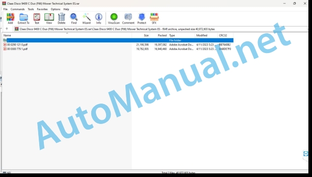
Claas Disco 9400 C Duo (F66) Mower Technical System ES
$150.00
- Model: Disco 9400 C Duo (F66) Mower
- Type Of Manual: Technical System
- Language: ES
- Format: PDF(s)
- Size: 34.7 MB
File List:
00 0290 121 0.pdf
00 0300 779 1.pdf
00 0290 121 0.pdf:
1. Introduction
Validity of instructions
2 DISCO 3000 TC, TRC, AS, FG – hydraulic installation
Hydraulic connection diagram
Connection diagram DISCO 3000 TC, TRC, AS, FG
Denominations
3 DISCO 2700, 3100, 3500 Contour – hydraulic installation
Hydraulic connection diagram
Connection diagram
Denominations
Function Description
Hydraulic cylinder working / transport position (3169)
Function Description
4 DISC 3050 TCAS
Hydraulic connection diagram
Hydraulic connection diagram
Denominations
Location of components
Setting the speed of the swath belt
Troubleshooting
5 DISC 3100 Contour / 2700C Contour
Hydraulic connection diagram
Connection diagram
Denominations
Function Description
Hydraulic cylinder working / transport position (3169)
Function Description
Unilateral check throttle valve
Denominations
Location of components
6 DISC 3100C
Hydraulic connection diagram
Connection diagram
Denominations
Function Description
Hydraulic cylinder working / transport position (3169)
Function Description
Unilateral check throttle valve
Denominations
7 DISC 3500C
09 Hydraulic installation main group
Connection diagram
Denominations
Function Description
Hydraulic cylinder working / transport position (3169)
Function Description
Unilateral check throttle valve
Denominations
Location of components
8 DISC 3900
Hydraulic connection diagram
Connection diagram
Denominations
Function Description
Hydraulic cylinder working / transport position (3169)
Function Description
Unilateral check throttle valve
Denominations
Location of components
9 DISCO 8550C – hydraulic installation
Hydraulic connection diagram
Connection diagram
Denominations
10 DISCO 8550C – electrical installation
Electrical connection diagram
Connection diagram
Denominations
11 DISCO 8550 C Plus – hydraulic installation
Hydraulic connection diagram
Connection diagram
Denominations
12 DISCO 8550 C Plus – electrical installation
Electrical connection diagram
Connection diagram
Denominations
Male plug/female plug
Plug X1 to X4 on the CCT (CLAAS-Control-Terminal)
Location of components
Representation
RPM controller
Adjustment
Function Description
Function failure
13 DISCO 8550 AS – electrical installation
Row shifter (belt drive)
Connection diagram (DIN A3)
Denominations
Function Description
Adapt tape speeds
Function Description
Menu A left ribbon
Menu B right ribbon
Location of components
Representation
14 DISCO 8550 AS – hydraulic installation
Global wiring diagram
Hydraulic connection diagram for raising/lowering mowers and row shifters
Denominations
Row shifter hydraulic connection diagram (belt drive)
Denominations
Functions of the global hydraulic system
Raise the mowers, raise the row shifters
Lower mowers, lower row shifters
Row shifter
Location of components
Graphic representation
15 DISCO 8500 C-6 = 695SL, 8500 C-8 = 820-880, JAGUAR 8500 C – Hydraulic installation
Global wiring diagram
Connection diagram (DIN A3)
Denominations
Location of components
Function Description
16 DISCO 8500 C-6, 8500 C-8, JAGUAR 8500 C – electrical installation
Global wiring diagram
Connection diagram (DIN A3)
Denominations
Function Description
central electrical system
Denominations
Central electrical system from 2000
Denominations
Central electrical system until 2000
Denominations
Switch/Pin occupation on the CCT (CLAAS-Control-Terminal)
Denominations
17 JAGUAR 8700/8500, DISCO 8700 Plus – hydraulic installation
Global wiring diagram
Connection diagram (DIN A3)
Denominations
18 JAGUAR 8700/8500, DISCO 8700 Plus – electrical installation
Overall wiring diagram of machines nr. 492 00 503 to 492 00 512
Connection diagram (DIN A3)
Denominations
CCT Pin Occupation
MFG Pin Occupation
Block wiring diagram
Location of components
Overall wiring diagram starting from machine no. 492 00 513
Connection diagram (DIN A3)
Denominations
CCT Pin Occupation
MFG Pin Occupation
Block wiring diagram
Location of components
19 DISCO 8700 Plus, DISCO 8550 C-8 for JAGUAR 880-820 (491) – electrical installation
Global wiring diagram
Connection diagram (DIN A3)
Denominations
CCT Pin Occupation
MFG Pin Occupation
Block connection diagram from machine no.:652 01278 and type 654 from year of manufacture 2002
Block connection diagram from machine no.: 652…, 654…
Location of components
RPM controller
Adjustment
Function Description
Function failure
RPM controller plug
20 DISCO 8700 Plus, DISCO 8550 C-8 for JAGUAR 880-820 (491) – hydraulic installation
Global wiring diagram
Connection diagram (DIN A3)
Denominations
21 DISC 9100 – 8400
09 Hydraulic installation main group
General connection diagram with protection bracket
Denominations
General connection diagram without protection bracket
Denominations
10 Main electrical installation group
Electrical connection diagram DISCO 9100 – 8400 with CST
Denominations
Electrical connection diagram DISCO 9100 – 8400 with ISO-BUS
Denominations
Mower control module (A68), additional mower control module (A111)
Denominations
Mower control module (A068) – socket assignment
Module A068 – plug X1
Module A068 – plug X2
Additional mower control module (A111) – socket assignment
Additional module A111 – socket X1
Additional module A111 – socket X2
Location of components
Individual components
22 DISC 9300C – 8600C with reversing device
09 Hydraulic installation main group
Global wiring diagram
Function Description
Valve block
23 DISCO 9300 – 8600 without reversing device
09 Hydraulic installation main group
Global wiring diagram
Valve block
24 DISC 9300 – 8600
10 Main electrical installation group
Electrical connection diagram DISCO 9300 – 8600 with CST (CLAAS Standard Terminal)
Denominations
Electrical connection diagram DISCO 9300 – 8600 with ISO-BUS
Denominations
Electromagnetic coil fold, unfold the protective stirrup
Denominations
Mower control module (A68), additional mower control module (A111)
Denominations
Mower control module (A068) – socket assignment
Module A068 – plug X1
Module A068 – plug X2
Location of components
Individual components
00 0300 779 1.pdf:
DISC 9400
Introduction
Safety instructions
Safety and danger instructions
Manual validity
CCN Explanation
CCN (CLAAS Component Number)
General indications
Electrical regulations
Hydraulic regulations
CCN (CLAAS Component Number)
09 Hydraulic
0900 General instructions for the hydraulic installation
Hydraulic functions
Function description – connection to the tractor hydraulic system
0920 Valves
Valve block (1406200.x) DISCO 9400 – up to machine no. F6601096
Valve block (2627366.x) DISCO 9400 – from machine no. F6601097
0980 Hydraulic connection diagram
DISCO 9400 (Duo) hydraulic connection diagram
10 Install. electrical/electronic
1012 Modules / sensors
Mower control module (A068), expansion module (A099), additional mower control module (A111)
A068 – Mower control module
Pin assignment of module A068 – socket X1
Pin assignment of module A068 – socket X2
A099 – Expansion module
Pin assignment of module A099 – socket X1
Pin assignment of module A099 – socket X2
A111 – Additional mower control module
Pin assignment of module A111 – socket X1
Pin assignment of module A111 – socket X2
1080 Electronic connection diagram
DISCO 9400 electrical connection diagram
SCM 01 – Power supply / CAN Bus
SCM 03 – Hydraulic functions
Denominations
SCM 04 – Left outgoing unit
Denominations
SCM 05 – Right outgoing unit
Denominations
SCM 06 – Front mower unit
Denominations
SCM 07a – Lighting
Denominations
SCM 07b – LED Lighting
Denominations
SCM 08 – Options
Denominations
SCM 10 – Modules
1081 Plug summary
Socket database (chp CLAAS)
Example of key number representation (CHP)
Key number (CHP)
Plug Representation (CHP)
1085 Networks
1097 Check/measure/adjust
sensory system
92 Diagnosis
9210 Machine Error Codes
FMI fault code (Failure Mode Indicator)
General indications
FMI 00 (signal too large)
FMI 01 (signal too small)
IMF 02 (implausible signal)
FMI 03 (voltage too high)
FMI 04 (voltage too low)
FMI 05 (current too low)
FMI 06 (current too high)
FMI 07 (mechanical failure)
FMI 08 (frequency signal defective)
IMF 09 (communication failure)
FMI 10 (signal change too fast)
IMF 11 (multiple failure)
FMI 12 (defective ECU)
FMI 13 (signal outside calibration range)
IMF 16 (non-existent parameter)
FMI 17 (ECU not responding)
FMI 18 (power supply failure)
FMI 19 (software requirements not met)
IMF 95 (no signal change)
FMI 96 (CAN-Bus system defective)
IMF 97 (implausible state)
IMF 98 (warning)
IMF 99 (Info)
Fault codes DISCO 9200 Standard
DTC (Diagnostic Trouble Code) Summary
Location of components
Hydraulic installation
3000 Hydraulic Cylinders
SectionHead
5000 Pressure accumulators
6000 Valves with mechanical drive
7000 Hydraulically Actuated Valves
Electrical installation
To Modules
B Sensors
C Electrical/electronic devices
and lighting
and electromagnetic valves
John Deere Repair Technical Manual PDF
John Deere Transmission Control Unit Component Technical Manual CTM157 15JUL05
John Deere Repair Technical Manual PDF
John Deere Repair Technical Manual PDF
John Deere 18-Speed PST Repair Manual Component Technical Manual CTM168 10DEC07
John Deere Repair Technical Manual PDF
John Deere Repair Technical Manual PDF
John Deere Repair Technical Manual PDF
John Deere Repair Technical Manual PDF
John Deere PowerTech M 10.5 L and 12.5 L Diesel Engines COMPONENT TECHNICAL MANUAL CTM100 10MAY11


