Claas Front Loader C (B92) Tractors Operator Manual ES
$50.00
- Model: Front Loader C (B92) Tractors
- Type Of Manual: Operator Manual
- Language: ES
- Format: PDF(s)
- Size: 10.8 MB
File List:
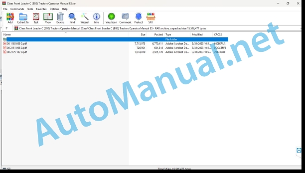
00 1165 939 0.pdf
00 2151 098 0.pdf
00 2175 182 0.pdf
00 1165 939 0.pdf:
MANUBALC40-C30-U40L6000-L500-L40V7000-V500-V60-V50-V40W500
1 Regarding this instruction manual
1.1 Information regarding the instruction manual
1.1.1 Use the user manual
Important information about this user manual
Structuring according to the MANUBAL subsets
Search and find
Direction signs
Specific terminology
Optional equipment and supplementary equipment
1.1.2 Symbols and instructions
Texts and illustrations
Indication of dangers and warnings
1.1.3 Technical instructions
2 Security
2.1 Safety regulations
2.1.1 Recommendations
2.1.2 Use according to assignment
2.1.3 Use not in accordance with the assignment
2.1.4 Safety and accident prevention instructions
2.1.5 MANUBAL
2.1.6 Checking the status of the MANUBAL
2.1.7 Adjustment, maintenance or repair work
2.1.8 Circulation and transportation
2.1.9 Safety regulations
2.1.10 Safety stickers
3 Machine Description
3.1 Identification plate and serial number
3.1.1 Identification plate
3.2 Overview
3.2.1 Description
bale clamps
Clamps for bales
Fittings
Bale spikes
3.3 Optional equipment
3.3.1 Wrapped Bale Clamp Kit
3.3.2 Lower spike kit
3.3.3 Spike length
3.3.4 Additional spikes
3.3.5 Enhancement
4 Technical data
4.1 MANUBAL
4.1.1 Characteristics of the MANUBAL with bale clamps
4.1.2 Characteristics of the MANUBAL with bale spikes
5 Preparation of the machine
5.1 Towing device
5.1.1 HANDLE Hitch
Case of a tool holder frame with manual release
5.1.2 Unhooking the MANUBAL
Case of a tool holder frame with manual release
5.2 Settings for use at work
5.2.1 Gripper opening/closing adjustment
Cylindrical bale
rectangular bale
5.2.2 MANUBAL W500 2nd bale detector
Operating principle
Detector adjustment
Forced activation of the detector
5.2.3 MANUBAL C40 — Setting the Power control system
5.2.4 Position of the tips of the bale spikes
Fixed spike position
Floating Spikes Position
inclined position
Position of retractable spikes on the road
5.2.5 MANUBAL V7000 with lower spikes
Lower spike configuration
Parking position
5.2.6 Spike separation
5.3 Optional equipment
5.3.1 Wrapped Bale Clamp Kit
Wrapped bale clamp open/close adjustment
Mounting the wrapped bale clamps
5.3.2 Lower spike kit
Lower spike configuration
Parking position
Spike spacing adjustment
5.3.3 Enhancement
6 Management
6.1 MANUBAL
6.1.1 Gripping bales due to their cylindrical surface
6.1.2 Gripping of bales due to their flat surface
6.2 MANUBAL V50
6.2.1 Change of position of the clamp
7 Maintenance
7.1 Maintenance instructions
7.1.1 Cleaning the MANUBAL
7.2 General maintenance instructions
7.2.Mntenance and storage
Maintenance
Parking lot
7.3 Greasing scheme
7.3.1 Greasing
8 EC declaration of conformity
8.1 MANUBAL
8.1.1 MANUBAL C40, C30, L6000, L500, L40, U40, V7000, V500, V60, V50, V40, W500
00 2151 098 0.pdf:
1. INSTRUCCIONES PARA EL USUARIO
2. NORMAS DE SEGURIDAD
3. ADHESIVOS DE SEGURIDAD
4. PLACA DE IDENTIFICACIÓN
5. ÁMBITO DE USO
6. PROCEDIMIENTO DE USO
7. CARACTERÍSTICAS TÉCNICAS
CERTIFICADO DE CONFORMIDAD
00 2175 182 0.pdf:
Front loader FL 120C-100C-80C-60C
1 Regarding this instruction manual
1.1 Information regarding the instruction manual
1.1.1 Recommendations on the use of the manual
2 Security
2.1 Safety instructions
2.1.1 Recommendations
2.1.2 Use according to assignment
2.1.3 Use not in accordance with the assignment
2.1.4 Safety and accident prevention instructions
2.1.5 Precautions necessary beforet-up
2.1.6 Front loader status check2.1.7 Adjustment, maintenance or repair work
2.1.8 Circulation and transportation
2.1.9 Lifting safety
2.1.10 Use of the front loader
2.1.11 Use of front loader implements
2.2 Safety instructions on the machine
2.2.1 General advice regarding safety markings
2.2.2 Safety stickers
3 Machine Description
3.1FL 120C-60C
3.1.1 Description
3.1.2 Description
3.1.3 Homologation
3.1.4 Compatibility of CLAAS front loaders and tractors
3.1.5 “FITLOCK” hitch system
3.1.6 Level indicator
3.1.7 Tool holder frames
MASTER-ATTACH tool holder frame
“EURO” tool holder frame
“MASTER-ATTACH/EURO” tool holder frame
“EURO/SMS-ALÖ3” tool holder frame
3.2 Optional equipment
3.2.1 “SHOCK ELIMINATOR SYSTEM”
3.2.2 “MACH SYSTEM”
3.2.3 “FASTLOCK” implement lock
3.2.4 Additional functions
Third function
Fourth function
“MACH 2” system
3.3 Additionastructure
3.3.2 Front implements
Sp bale clamps
4 Control and display instruments
4.1 Front loader controls
4.1.1 “FLEXPILOT” lever
4.1.2 “PROPILOT” lever
4.1.3 Multifunction lever (ARION 400)
4.1.4 “ELECTROPILOT” lever (ARION 500/600)
5 Technical data
5.1 FL 120C-60C
5.1.1 Characteristics of front loaders
6 Preparation of the machine
6.1FL 120C-60C
6.1.1 Front loader hitch
6.1.2 Hitching difficulties
6.1.3 Front loader release
6.1.4 Preparation of tool holders
“MASTER-ATTACH/EURO” tool holder frame
“EURO/SMS-ALÖ3” tool holder frame
6.1.5 Preparation of the level indicator
6.2 Head
6.2.1 Hitching the implement with a manual release tool holder frame
6.2.2 Hitching the implement with a tool frame with “FASTLOCK” release
6.2.3 Uncoupling the implement with a manual release frame
6.2.4 Uncoupling the implement with a tool frame with “FASTLOCK” release
6.3 Ballas
6.3.2 Ballast type
7 Management
7.1 Front loader controls
7.1.1 Han pressure points at the rear of the tractor
7.1.2 Using the “FLEXPILOT” command
Lock and unlock
Charger Features
Implement functions
7.1.3 Using the “PROPILOT” command
Lock and unlock
Charger Features
Implement function
7.1.4 Using the multifunction lever (ARION 400)
Lock and unlock
Charger Features
Implement function
7.1.5 Use of the “ELECTROPILOT” control (ARION 500/600)
Lock and unlock
Charger Features
Implement function
7.2 Additional equipment
7.2.1 Use of “SHOCK ELIMINATOR SYSTEM”
Manual valve
Electrohydraulic valve
8 Maintenance
8.1 FL 120C-60C
8.1.1 Transport/handling
8.1.2 Intervention on the tractor with loader
8.1.3 Cleaning the front loader
8.1.4 Tightening control
8.1.5 Greasing
Front loader
9 EU declaration of conformity
9.1 Fron.1 FL 120C-100C-80C-60C
10 Technical dictionary and abbreviations
10.1 Units
John Deere Repair Technical Manual PDF
John Deere Repair Technical Manual PDF
John Deere Diesel Engines PowerTech 4.5L and 6.8L – Motor Base Technical Manual 07MAY08 Portuguese
John Deere Parts Catalog PDF
John Deere Harvesters 8500 and 8700 Parts Catalog CPCQ24910 Spanish
John Deere Repair Technical Manual PDF
John Deere Repair Technical Manual PDF
John Deere Repair Technical Manual PDF
John Deere Diesel Engines POWERTECH 2.9 L Component Technical Manual CTM126 Spanish
John Deere Repair Technical Manual PDF
John Deere Parts Catalog PDF
John Deere Tractors 7500 Parts Catalog CPCQ26568 30 Jan 02 Portuguese
John Deere Repair Technical Manual PDF


