Claas GPS PILOT – Steer ready (B86) Digital solutions Operator Manual DE
$50.00
- Model: GPS PILOT – Steer ready (B86) Digital solutions
- Type Of Manual: Operator Manual
- Language: DE
- Format: PDF(s)
- Size: 360 MB
File List:
– 00 0018 530 0.pdf
– 00 0018 583 4.pdf
– 00 0018 646 2.pdf
– 00 0018 651 1.pdf
– 00 0301 050 0.pdf
– 00 0303 481 0.pdf
– 00 1400 091 0.pdf
– 00 1400 463 5.pdf
– 00 1400 634 3.pdf
– 00 1400 859 2.pdf
– 00 1402 752 1.pdf
– 00 1405 160 7.pdf
– 00 1405 180 7.pdf
– 00 1420 023 4.pdf
– 00 1420 051 2.pdf
– 00 2348 299 0.pdf
– 00 2666 665 5.pdf
00 0018 530 0.pdf
Table of Content:
1 BASELINE HD base station
2 Table of Contents
3 1 About these operating instructions
3.1 1.1 Notes on the instructions
4 2 Security
4.1 2.1 Intended use
4.2 2.2 Safety instructions
4.3 2.3 Safety instructions in these instructions
5 3 Product description
5.1 3.1 Overview and functionality
5.2 3.2 Type plates and identification numbers
6 4 Control and display elements
6.1 4.1 BASELINE HD
7 5 Technical data
7.1 5.1 BASELINE HD
8 6 Prepare product
8.1 6.1 BASELINE HD base station
8.2 6.2 Initial commissioning correction signal
9 7 Operation
9.1 7.1 BASELINE HD base station
9.2 7.2 Settings
10 8 Malfunction and remedy
10.1 8.1 Malfunction and remedy
11 9 Decommissioning and disposal
11.1 9.1 Decommissioning and disposal
12 10 technical terms and abbreviations
12.1 10.1 Terms and explanations
00 0018 583 4.pdf
Table of Content:
1 EASY on board App
2 Table of Contents
3 1 Introduction
3.1 1.1 Notes on the instructions
3.2 1.2 Intended use
3.3 1.3 Software update
3.4 1.4 Malfunction and remedy
3.5 1.5 Technical terms and abbreviations
4 2 Security
4.1 2.1 Recognize warnings
4.2 2.2 Safety instructions
5 3 EASY on board App
5.1 3.1 Control and display elements
5.2 3.2 Operation
6 4 Documentation
6.1 4.1 Product description
6.2 4.2 Control and display elements
6.3 4.3 Create order
6.4 4.4 Documentation
7 5 ISO Terminal
7.1 5.1 Product description
7.2 5.2 Control and display elements
7.3 5.3 Programmable buttons
8 6 Settings
8.1 6.1 Control and display elements
8.2 6.2 Settings
9.1 7.1 Settings
00 0018 651 1.pdf
Table of Content:
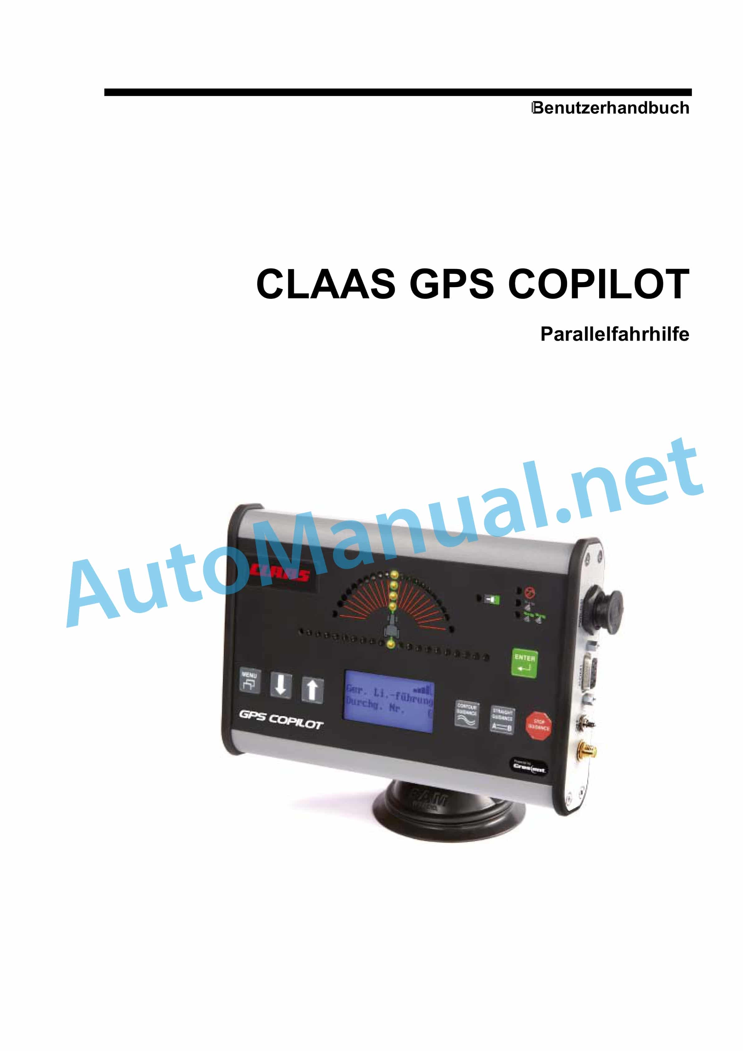
1 Quick guide GPS COPILOT
1.1 General
1.2 AB mode
1.3 Contour Mode
1.4 Change in working width
1.5 Change of signal type
1.6 Area measurement
1.7 Automatic A-B line shift
00 0301 050 0.pdf
Table of Content:
1 PROFI CAM 3
2 Table of Contents
3 1 Introduction
3.1 1.1 Notes on the instructions
3.2 1.2 Intended use
4 2 Security
4.1 2.1 Recognize warnings
4.2 2.2 Safety instructions
5 3 Product description
5.1 3.1 Overview and functionality
5.2 3.2 Type plates and identification number
5.3 3.3 Information on the product
6 4 Control and display elements
6.1 4.1 Camera system
6.2 4.2 Menu structure
7 5 Technical data
7.1 5.1 PROFI CAM
8 6 Prepare product
8.1 6.1 Switch off and secure the machine
8.2 6.2 Carry out before commissioning
9 7 Operation
9.1 7.1 Monitor
10 8 Malfunction and remedy
10.1 8.1 Electrics and electronics
11 9 Maintenance
11.1 9.1 Maintenance intervals
11.2 9.2 Camera system
12 10 Decommissioning and disposal
12.1 10.1 General information
13 11 technical terms and abbreviations
13.1 11.1 Abbreviations
00 0303 481 0.pdf
Table of Content:
1 PROFI CAM 4
2 Table of Contents
3 1 Introduction
3.1 1.1 Notes on the instructions
3.2 1.2 Intended use
4 2 Security
4.1 2.1 Recognize warnings
4.2 2.2 Safety instructions
5 3 Product description
5.1 3.1 Overview and functionality
5.2 3.2 Type plates and identification number
5.3 3.3 Information on the product
6 4 Control and display elements
6.1 4.1 Camera system
6.2 4.2 Menu structure
7 5 Technical data
7.1 5.1 PROFI CAM
8 6 Prepare product
8.1 6.1 Switch off and secure the machine
8.2 6.2 Carry out before commissioning
9 7 Operation
9.1 7.1 Monitor
10 8 Malfunction and remedy
10.1 8.1 Electrics and electronics
11 9 Maintenance
11.1 9.1 Maintenance intervals
11.2 9.2 Camera system
12 10 Decommissioning and disposal
12.1 10.1 General information
13 11 technical terms and abbreviations
13.1 11.1 Abbreviations
00 1400 091 0.pdf
Table of Content:
1 CULTI CAM
2 Table of Contents
3 1 About these operating instructions
3.1 1.1 Notes on the instructions
4 2 Security
4.1 2.1 Safety instructions
4.2 2.2 Safety instructions in these instructions
4.3 2.3 Safety devices
5 3 Product description
5.1 3.1 Overview and functionality
5.2 3.2 Optional equipment
5.3 3.3 Type plates and identification numbers
6 4 Control and display elements
6.1 4.1 COMMUNICATOR II
6.2 4.2 CULTI CAM
7 5 Technical data
7.1 5.1 COMMUNICATOR II
7.2 5.2 CULTI CAM
8 6 Prepare product
8.1 6.1 General information
8.2 6.2 Carry out before commissioning
8.3 6.3 Cultivation
8.4 6.4 CULTI CAM
9 7 Operation
9.1 7.1 Driving on the road
9.2 7.2 Switch COMMUNICATOR II on/off
9.3 7.3 COMMUNICATOR II Programmable buttons
9.4 7.4 COMMUNICATOR II ISOBUS settings
9.5 7.5 COMMUNICATOR II Terminal Settings
9.6 7.6 Work input
10 8 Malfunction and remedy
10.1 8.1 Overview of faults
11 9 Maintenance
11.1 9.1 General information
11.2 9.2 Maintenance instructions
12 10 Service
12.1 10.1 General information
13 11 Decommissioning and disposal
13.1 11.1 General information
14 12 technical terms and abbreviations
14.1 12.1 Terms and explanations
00 1400 463 5.pdf
Table of Content:
1 GPS PILOTGPS PILOT FLEX
2.1 1.1 Homologation
3.1 2.1 Homologation
4.1 3.1 Homologation
5.1 4.1 a 12.1 11.1 Homologacija
13.1 12.1 Homologizci
14.1 13.1 Omologazione
15.1 14.1 Homologacija
16.1 15.1 Homologcija
17.1 16.1 Homologacy
18.1 17.1 Homologacja
19.1 18.1 Homologao
20.1 19.1 Omologare
21.1 20.1 Homologizcia
22.1 21.1 Homologacija
23.1 22.1 Frskran
7.2 5.2 S7 Terminal
8 6 Prepare product
8.1 6.1 Switch off and secure the machine
8.2 6.2 Carry out before commissioning
8.3 6.3 Initial commissioning machine
8.4 6.4 Initial commissioning of the implement
8.5 6.5 Initial commissioning correction signal
8.6 6.6 Set subscriptions
9 7 Operation
9.1 7.1 Checklists
9.2 7.2 GPS COPILOT
9.3 7.3 GPS Settings
9.4 7.4 System Settings
9.5 7.5 Vehicle settings
9.6 7.6 Device settings
9.7 7.7 Order management
9.8 7.8 Field trip with GPS COPILOT
9.9 7.9 Boundaries and markers
9.10 7.10 Straight lines
9.11 7.11 Circular line guidance
9.12 7.12 Contour line guidance
9.13 7.13 Section display
10 8 Malfunction and remedy
10.1 8.1 Errors and measures
10.2 8.2 S7 Terminal
10.3 8.3 Diagnosis
11 9 Maintenance
11.1 9.1 Overview of maintenance intervals
12 10 Decommissioning and disposal
12.1 10.1 General information
13 11 EC declaration of conformity
13.1 11.1 GPS COPILOT
14 12 technical terms and abbreviations
14.1 12.1 GPS COPILOT
00 1400 859 2.pdf
Table of Content:
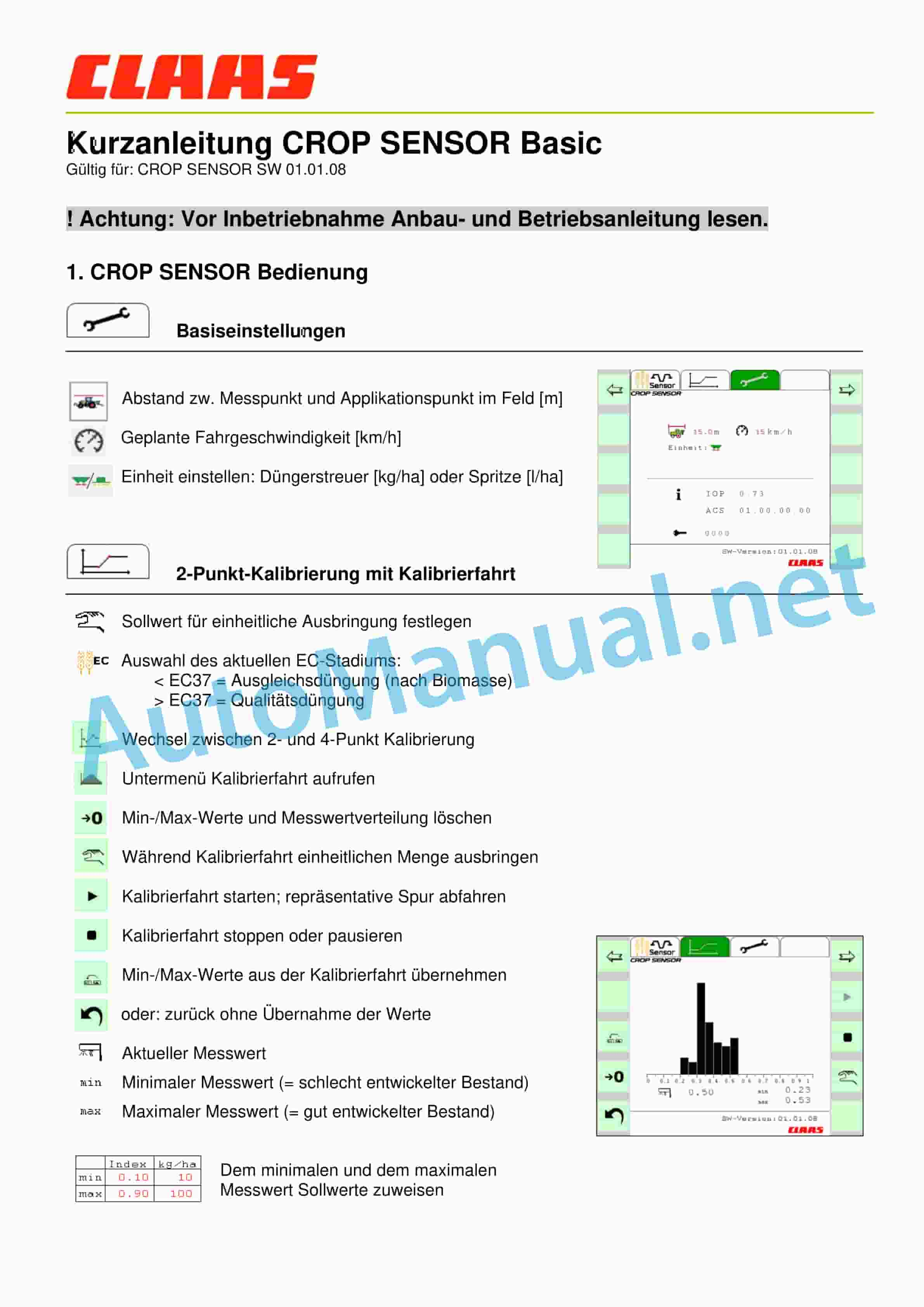
1 Quick guide CROP SENSOR Basic
1.1! Attention: Read the installation and operating instructions before commissioning.
1.2 1. CROP SENSOR Operation
2 Attention: If the application rate is limited by the min/max quantity, this is only possible on the work screen via the display
3 2. Status and error messages
00 1402 752 1.pdf
Table of Content:
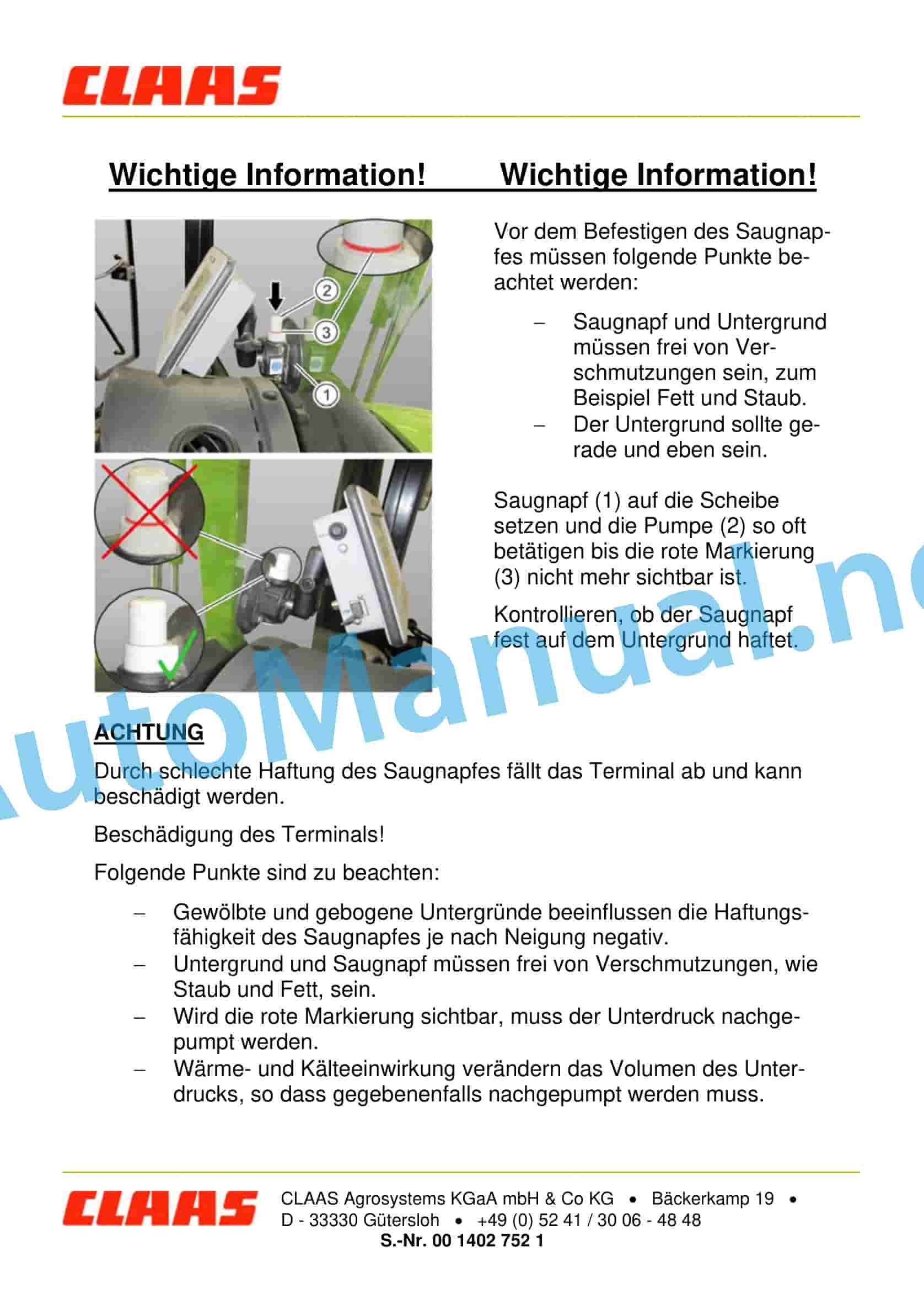
1 Important information! Important information!
1.1 ATTENTION
00 1405 160 7.pdf
Table of Content:
1 GPS PILOT
2 Table of Contents
3 1 Introduction
3.1 1.1 General information
3.2 1.2 Intended use
4 2 Security
4.1 2.1 Recognize warnings
4.2 2.2 Safety instructions
5 3 Product description
5.1 3.1 Overview and functionality
5.2 3.2 Safety devices
5.3 3.3 Optional equipment
5.4 3.4 Type plates and identification numbers
6 4 Control and display elements
6.1 4.1 GPS PILOT
6.2 4.2 Overview S10 Terminal
6.3 4.3 Menu structure GPS PILOT
6.4 4.4 Application ISO UT
6.5 4.5 Camera application
7 5 Technical data
7.1 5.1 GPS PILOT
7.2 5.2 S10 Terminal
8 6 Prepare product
8.1 6.1 Switch off and secure the machine
8.2 6.2 Carry out before commissioning
8.3 6.3 Initial commissioning machine
8.4 6.4 Initial commissioning of the implement
8.5 6.5 Section display and section control settings
8.6 6.6 Initial commissioning correction signal
8.7 6.7 Set subscriptions
9 7 Operation
9.1 7.1 Checklists
9.2 7.2 S10 Terminal
9.3 7.3 GPS PILOT
9.4 7.4 System Settings
9.5 7.5 GPS Settings
9.6 7.6 Map Settings
9.7 7.7 Vehicle settings
9.8 7.8 Device settings
9.9 7.9 Driver profiles
9.10 7.10 Product profiles
9.11 7.11 Order management
9.12 7.12 ISOBUS order management
9.13 7.13 Field trip with GPS PILOT
9.14 7.14 Limits
9.15 7.15 Straight lines
9.16 7.16 Circular line guidance
9.17 7.17 Contour line guidance
9.18 7.18 AB contour line guidance
9.19 7.19 TURN IN*
9.20 7.20 AUTO TURN*
9.21 7.21 Section display and section control
9.22 7.22 Quantity control
9.23 7.23 Mapping Options
9.24 7.24 ISO UT
9.25 7.25 Camera
9.26 7.26 Favorites
10 8 Malfunction and remedy
10.1 8.1 Errors and measures
10.2 8.2 S10 Terminal
10.3 8.3 Navigation computer
10.4 8.4 Module
10.5 8.5 Diagnosis
11 9 Maintenance
11.1 9.1 Overview of maintenance intervals
11.2 9.2 GPS PILOT
12 10 Decommissioning and disposal
12.1 10.1 General information
13 11 EC declaration of conformity
13.1 11.1 GPS PILOT
14 12 Homologation
14.1 12.1 GPS PILOT
15 13 technical terms and abbreviations
15.1 13.1 GPS PILOT
00 1405 180 7.pdf
Table of Content:
1 GPS PILOT
2 Table of Contents
3 1 Introduction
3.1 1.1 General information
3.2 1.2 Intended use
4 2 Security
4.1 2.1 Recognize warnings
4.2 2.2 Safety instructions
5 3 Product description
5.1 3.1 Overview and functionality
5.2 3.2 Safety devices
5.3 3.3 Optional equipment
5.4 3.4 Type plates and identification numbers
6 4 Control and display elements
6.1 4.1 GPS PILOT
6.2 4.2 Overview S7 Terminal
6.3 4.3 Menu structure GPS PILOT
7 5 Technical data
7.1 5.1 GPS PILOT
7.2 5.2 S7 Terminal
8 6 Prepare product
8.1 6.1 Switch off and secure the machine
8.2 6.2 Carry out before commissioning
8.3 6.3 Initial commissioning machine
8.4 6.4 Initial commissioning of the implement
8.5 6.5 Initial commissioning correction signal
8.6 6.6 Set subscriptions
9 7 Operation
9.1 7.1 Checklists
9.2 7.2 S7 Terminal
9.3 7.3 GPS PILOT
9.4 7.4 GPS Settings
9.5 7.5 System Settings
9.6 7.6 Vehicle settings
9.7 7.7 Device settings
9.8 7.8 Order management
9.9 7.9 Field trip with GPS PILOT
9.10 7.10 Boundaries and markers
9.11 7.11 Straight lines
9.12 7.12 Contour line guidance
9.13 7.13 AB contour line guidance
9.14 7.14 Circular line guidance
9.15 7.15 TURN IN*
9.16 7.16 AUTO TURN*
9.17 7.17 Section display
10 8 Malfunction and remedy
10.1 8.1 Errors and measures
10.2 8.2 S7 Terminal
10.3 8.3 Navigation computer
10.4 8.4 Module
10.5 8.5 Diagnosis
11 9 Maintenance
11.1 9.1 Overview of maintenance intervals
11.2 9.2 GPS PILOT
12 10 Decommissioning and disposal
12.1 10.1 General information
13 11 EC declaration of conformity
13.1 11.1 GPS PILOT
14 12 Homologation
14.1 12.1 GPS PILOT
15 13 technical terms and abbreviations
15.1 13.1 GPS PILOT
00 1420 023 4.pdf
Table of Content:
1 GPS PILOT
2 Table of Contents
3 1 Introduction
3.1 1.1 General information
3.2 1.2 Intended use
4 2 Security
4.1 2.1 Recognize warnings
4.2 2.2 Safety instructions
5 3 Product description
5.1 3.1 Overview and functionality
5.2 3.2 Safety devices
5.3 3.3 Optional equipment
5.4 3.4 Type plates and identification numbers
6 4 Control and display elements
6.1 4.1 GPS PILOT
6.2 4.2 Overview S10 Terminal
6.3 4.3 Menu structure GPS PILOT
6.4 4.4 Application ISO UT
6.5 4.5 Camera application
7 5 Technical data
7.1 5.1 GPS PILOT
7.2 5.2 S10 Terminal
8 6 Prepare product
8.1 6.1 Switch off and secure the machine
8.2 6.2 Carry out before commissioning
8.3 6.3 Initial commissioning machine
8.4 6.4 Initial commissioning of the implement
8.5 6.5 Section display and section control settings
8.6 6.6 Initial commissioning correction signal
8.7 6.7 Set subscriptions
9 7 Operation
9.1 7.1 Checklists
9.2 7.2 S10 Terminal
9.3 7.3 GPS PILOT
9.4 7.4 System Settings
9.5 7.5 GPS Settings
9.6 7.6 Map Settings
9.7 7.7 Vehicle settings
9.8 7.8 Device settings
9.9 7.9 Driver profiles
9.10 7.10 Product profiles
9.11 7.11 Order management
9.12 7.12 ISOBUS order management
9.13 7.13 Field trip with GPS PILOT
9.14 7.14 Limits
9.15 7.15 Straight lines
9.16 7.16 Circular line guidance
9.17 7.17 Contour line guidance
9.18 7.18 AB contour line guidance
9.19 7.19 TURN IN*
9.20 7.20 AUTO TURN*
9.21 7.21 Section display and section control
9.22 7.22 Quantity control
9.23 7.23 Mapping Options
9.24 7.24 ISO UT
9.25 7.25 Camera
9.26 7.26 Favorites
10 8 Malfunction and remedy
10.1 8.1 Errors and measures
10.2 8.2 S10 Terminal
10.3 8.3 Navigation computer
10.4 8.4 Diagnosis
11 9 Maintenance
11.1 9.1 Overview of maintenance intervals
11.2 9.2 GPS PILOT
12 10 Decommissioning and disposal
12.1 10.1 General information
13 11 EC declaration of conformity
13.1 11.1 GPS PILOT
14 12 Homologation
14.1 12.1 GPS PILOT
15 13 technical terms and abbreviations
15.1 13.1 GPS PILOT
00 1420 051 2.pdf
Table of Content:
1 GPS PILOT
2 Table of Contents
3 1 Introduction
3.1 1.1 General information
3.2 1.2 Intended use
4 2 Security
4.1 2.1 Recognize warnings
4.2 2.2 Safety instructions
5 3 Product description
5.1 3.1 Overview and functionality
5.2 3.2 Safety devices
5.3 3.3 Optional equipment
5.4 3.4 Type plates and identification numbers
6 4 Control and display elements
6.1 4.1 GPS PILOT
6.2 4.2 Overview S7 Terminal
6.3 4.3 Menu structure GPS PILOT
7 5 Technical data
7.1 5.1 GPS PILOT
7.2 5.2 S7 Terminal
8 6 Prepare product
8.1 6.1 Switch off and secure the machine
8.2 6.2 Carry out before commissioning
8.3 6.3 Initial commissioning machine
8.4 6.4 Initial commissioning of the implement
8.5 6.5 Initial commissioning correction signal
8.6 6.6 Set subscriptions
9 7 Operation
9.1 7.1 Checklists
9.2 7.2 S7 Terminal
9.3 7.3 GPS PILOT
9.4 7.4 GPS Settings
9.5 7.5 System Settings
9.6 7.6 Vehicle settings
9.7 7.7 Device settings
9.8 7.8 Order management
9.9 7.9 Field trip with GPS PILOT
9.10 7.10 Boundaries and markers
9.11 7.11 Straight lines
9.12 7.12 Circular line guidance
9.13 7.13 Contour line guidance
9.14 7.14 AB contour line guidance
9.15 7.15 TURN IN*
9.16 7.16 AUTO TURN*
9.17 7.17 Section display
10 8 Malfunction and remedy
10.1 8.1 Errors and measures
10.2 8.2 S7 Terminal
10.3 8.3 Navigation computer
10.4 8.4 Diagnosis
11 9 Maintenance
11.1 9.1 Overview of maintenance intervals
11.2 9.2 GPS PILOT
12 10 Decommissioning and disposal
12.1 10.1 General information
13 11 EC declaration of conformity
13.1 11.1 GPS PILOT
14 12 Homologation
14.1 12.1 GPS PILOT
15 13 technical terms and abbreviations
15.1 13.1 GPS PILOT
00 2348 299 0.pdf
Table of Content:
1 CEMIS 700
2 Table of Contents
3 1 Introduction
3.1 1.1 General information
3.2 1.2 Intended use
4 2 Security
4.1 2.1 Safety instructions
5 3 Product description
5.1 3.1 Overview and functionality
5.2 3.2 Type plates and identification numbers
6 4 Information on the product
6.1 4.1 Software version
7 5 Control and display elements
7.1 5.1 CEMIS 700
8 6 Technical data
8.1 6.1 CEMIS 700
9 7 Operation
9.1 7.1 CEMIS 700
9.2 7.2 Terminal Settings
10 8 Maintenance
10.1 8.1 Maintenance
11 9 Decommissioning and disposal
11.1 9.1 General information
12 10 technical terms and abbreviations
12.1 10.1 Terms and explanations
00 2666 665 5.pdf
Table of Content:
1 GPS PILOTGPS PILOT FLEX
2.1 1.1 Homologation
3.1 2.1 Homologation
4.1 3.1 Homologation
5.1 4.1 Homologacin
6.1 5.1 Homologao
John Deere Repair Technical Manual PDF
John Deere Repair Technical Manual PDF
John Deere Parts Catalog PDF
John Deere Tractors 7500 Parts Catalog CPCQ26568 30 Jan 02 Portuguese
John Deere Repair Technical Manual PDF
John Deere Transmission Control Unit Component Technical Manual CTM157 15JUL05
John Deere Parts Catalog PDF
John Deere Tractors 6300, 6500, and 6600 Parts Catalog CQ26564 (29SET05) Portuguese
John Deere Repair Technical Manual PDF
John Deere Repair Technical Manual PDF
John Deere Repair Technical Manual PDF
John Deere Parts Catalog PDF
John Deere Harvesters 8500 and 8700 Parts Catalog CPCQ24910 Spanish

