Claas Jaguar 880-830 (500) Forage Harvesters Repair Manual EN
$100.00
- Model: Jaguar 880-830 (500) Forage Harvesters
- Type Of Manual: Repair Manual
- Language: EN
- Format: PDF(s)
- Size: 57.2 MB
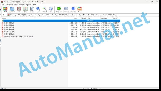
File List:
00 0296 365 1.pdf
00 0302 272 3.pdf
00 0303 918 0.pdf
00 0303 966 1.pdf
00 0305 072 0.pdf
00 0305 431 0.pdf
Inspection protocol OM 502 LA OM 460 LA.pdf
00 0296 365 1.pdf:
Mercedes-Benz OM460LA
Table of contents
Introduction
General information
Validity of manual
Handling the manual
Texts and figures
Document structure based on the assembly structure
Search and find
Directions
Abbreviations
Technical terms
General repair instructions
Technical specifications
Information on proper repairs
Self-locking bolts
Liquid locking compound
Steel roller chains
Tensioning
Chain connector
Taper ring fasteners
Dismounting
Installation
Gib head key joints
Dismounting
Installation
Lock collar bearing
Dismounting
Installation
Adapter sleeve bearings
Dismounting
Installation
Chuck bushing
Dismounting
Installation
Circlips
Ferrule fittings
Screwing in
Non-tight ferrule connection
Sealing cone fittings
Hydraulic hoses
Hose placement
Treatment of sealing faces
Spare parts
Torque settings
Tightening torques for metric standard threads
Tightening torques for metric fine thread screws
Tightening torques for hydraulic screw fittings and air conditioner screw fittings with sealing cone and O-ring according to DIN 3865
Tightening torques for hydraulic screw fittings with ferrule according to DIN 3861
Tightening torques for SDS hydraulic male connectors
Tightening torques for hydraulic swivel fittings
Tightening torques for hollow screws DIN 7643
Tightening torques for direction-adjustable SDE hydraulic male connectors
Tightening torques for brake line screw fittings
Tightening torques for worm drive hose clamps
Tightening torque for spring-loaded worm drive hose clamps
CCN explanation
CCN (CLAAS Component Number)
Electric systems standard
Hydraulic system standard
CCN (CLAAS Component Number)
General information
Of special importance
Identification of warning and danger signs
Regulations for avoiding accidents with personal injuries
Testing, adjusting and repair work
Engine operation
Suspended loads
Working on piping and hoses
Working on the electric system
Working on the hydraulic system
Electric welding
Painting work
Working with urea solution
Information on how to avoid damage and premature wear
Liability limitation
Shutting down and storage
Regulations for avoiding health and environmental damage
Precautionary measures for protection against health and environmental damage
Disposal of operating utilities and auxiliary operating utilities
Information for working on the diesel engine
Accident protection
Cleanliness
Installation instructions
Engine overhaul
Putting into operation after an engine overhaul
First aid measures
01 Engine
0102 Complete component
Type design
Engine data
Engine description
Engine components
Ignition order
Cranking the engine
Special tool for built-in engine
Special tools for removed engine
Cranking the engine in built-in condition:
JAGUAR double engine (A)
JAGUAR Double engine (B)
Cranking the engine in removed condition
0105 Engine suspension
Lifting eyes
Technical specifications
0110 Engine housing
Oil sump
Install special tool
Technical specifications
Installation
Crankshaft front seal
Special tool
Technical specifications
Removing the radial seal
Installing the radial seal
Removing the cassette seal
Installing the cassette seal ring
Crankshaft rear seal
Special tool
Technical specifications
Installation
Crankcase cover
Special tool
Technical specifications
Installation
Camshaft timing gear wheel cover
Technical specifications
Installation instructions
Timing housing
Work preparation
Technical specifications
Installation
Oil separator
Technical specifications
0115 Engine unit
Special tool
Technical specifications
Disassembly
Checking
Assembly
Installation
Installation
Measuring the excess dimension
Connecting rod
Technical specifications
Checking
Installation
Cylinder liner
Special tool
Technical specifications
Checking
Installation
Applies to design type: 458.99x
Measuring the excess dimension
Measuring the cylinder bore
Crankshaft
Install special tool
Technical specifications
Checking
Installation
Crankshaft ring
Special tool
Technical specifications
Installation
Oscillation damper
Technical specifications
Installation instructions
Flywheel
Special tool
Technical specifications
Checking
Installation
Replace ring gear
Replacing the ring
0120 Cylinder head / Valves / Idler gear
Valve cover
Technical specifications
Cylinder head
Special tool
Technical specifications
Checking
Disassembly
Assembly
Installation
Rocker lever
Special tool
Technical specifications
Installation instructions
Replacing the roller tappets
Special tool
Technical specifications
Installation instructions
Checking the valves
Adjusting the valve lash
Valve springs and valve stem seals
Special tool
Mercedes-Benz
Technical specifications
Installation
Valve guide
Work preparation
Special tool
Technical specifications
Checking
Installation
Camshaft
Install special tool
Technical specifications
Checking
Installation
Camshaft timing gear wheel
Technical specifications
0125 Injection / Fuel system
Fuel system
Cylinder head injection line
Special tool
Technical specifications
Installation instructions
Cylinder head leakage lines
Technical specifications
Nozzle holder combination
Special tool
Technical specifications
Installation
Protective sleeve
Special tool
Technical specifications
Installation instructions
Plug-on pump
Special tool
Work preparation
Technical specifications
Installation
Fuel pump
Work preparation
Technical specifications
Removing the bearing
Installing the bearing
Installation
Fuel filter housing
Technical specifications
0130 Lubricating oil system
Lubricating oil system
Install special tool
Pre-filling
Oil spray nozzle
Technical specifications
Installation instructions
Oil filter housing
Technical specifications
Installation
Oil cooler
Technical specifications
Installation instructions
Oil pump
Technical specifications
Installation instructions
Oil excess pressure valve
Technical specifications
Installation instructions
0135 Cooling system
Special tool
Technical specifications
Draining
Filling up
Cleaning the coolant circuit
Coolant pump
Technical specifications
Installation
Coolant thermostat
Work preparation
Technical specifications
Checking
Installation
0140 Exhaust system
Exhaust manifold
Technical specifications
Installation
Exhaust turbo charger
Special tool
Technical specifications
Installation
Checking
Checking the axial play
Checking the radial play
Flap nozzle
Technical specifications
Installation
Catalyst
Work preparation
Technical specifications
Installation instructions
0145 Air intake
Intake housing
Technical specifications
Installation
0150 Engine attachment parts
Electric starting motor
Work preparation
Technical specifications
Installation
Removing the solenoid switch
Installing the solenoid switch
Removing the starter pinion
Installing the starter pinion
Alternator
Special tool
Technical specifications
Installation
Removing the pulley
Installing the pulley
Alternator
Special tool
Technical specifications
Installation
Removing the pulley
Installing the pulley
Alternator drive belt tensioner
Technical specifications
Installation instructions
Air compressor
Technical specifications
Applies to design type 458.992
Installation
Applies to design type 458.992
Checking the oil thrown out
0155 Engine control
MR/PLD control unit
Technical specifications
Installation instructions
0165 Exhaust gas aftertreatment
Exhaust treatment system
Work preparation
Special tool
Technical specifications
Checking the urea solution (purity)
Checking the urea solution (density)
Urea heater valve
Work preparation
Special tool
Technical specifications
Installation
Urea pump
Work preparation
Special tool
Technical specifications
Installation
Removing the pressure accumulator
Installing the pressure accumulator
Removing the dump valve
Installing the dump valve
Removing the intake filter
Installing the intake filter
Checking the electric wiring loom
Filling the accumulator
Urea dosing unit
Work preparation
Special tool
Technical specifications
Installation instructions
Flushing
Urea injector
00 0302 272 3.pdf:
JAGUAR 960-930JAGUAR 880-840
Table of contents
Validity of manual
Validity of manual
General safety precautions
Important
Marking of warnings and hazard prevention notes
01 Engine
0135 Cooling system
Shipping package of repair kit OM 470
Shipping package of parts kit OM 470
Installation of repair kit OM 470 (00 2404 046 X)
Shipping package of repair kit OM 471 / OM 473
Shipping package of parts kit OM 471
Shipping package of parts kit OM 473
Installation of repair kit OM 470 / OM 473 (00 2404 050 X)
00 0303 918 0.pdf:
JAGUAR 990-830 Cooling system
Table of contents
Introduction
General information
Important!
Validity of manual
Shipping package
Repair kit 00 2791 292 0
Cooling system: Chaff screen cleaning
Modification
General safety precautions
Putting the machine out of operation
Removing the suction arm drive
Mounting
Installing the suction arm drive 00 2791 292 0
00 0303 966 1.pdf:
JAGUAR 990-830Chopping
Table of contents
Introduction
General information
Important!
Validity of manual
Shipping package
Repair kit 00 2926 032 0
Shear bar adjustment module A084 generation II (CLAAS JAGUAR 500, 496)
Modification
Sequence of work steps
Putting the machine out of operation
Removing shear bar adjustment module A084 (CLAAS JAGUAR 500, 496)
Mounting
Installing shear bar adjustment module A084 generation II (CLAAS JAGUAR 500, 496)
Shipping package
Repair kit 00 2406 842 1
Shear bar adjustment module A084 generation II (CLAAS JAGUAR 502, 499, 498)
Modification
Sequence of work steps
Putting the machine out of operation
Removing shear bar adjustment module A084 (CLAAS JAGUAR 502, 499, 498)
Mounting
Installing shear bar adjustment module A084 generation II (CLAAS JAGUAR 502, 499, 498)
Software, configuration and shear bar adjustment
Software update
Updating the SBM (shear bar adjustment module) A084 software
Configuration and backup
Checking the configuration and preparing a backup
Shear bar adjustment
Sharpening the knives and adjusting the shear bar clearance
00 0305 072 0.pdf:
JAGUAR 990-830Cooling system
Table of contents
Introduction
General information
Validity of manual
Quick navigation
Shipping package
Repair kit 00 2789 091 0
Rotary screen XL: Replacing the perforated plate
Modification
General safety precautions
Putting the machine out of operation
Important!
Removing the rotary screen
Assembly 00 2789 091 0
Rotary screen XL: Replacing the perforated plate
Installation
Installing the rotary screen
Shipping package
Repair kit 00 2789 092 0
Rotary screen M: Replacing the perforated plate
Modification
General safety precautions
Putting the machine out of operation
Important!
Removing the rotary screen
Assembly 00 2789 092 0
Rotary screen M: Replacing the perforated plate
Installation
Installing the rotary screen
00 0305 431 0.pdf:
Table of contents
Introduction
Safety rules
Safety and hazard information
Validity of manual
Validity of manual
99 Overall machine
9997 Testing / measuring / adjusting
Vibrations check list
1 Cleaning and adjusting the machine
2 Locating the area of vibrations
3 Vibrations in the drives
3.1 Main drive
3.2 Fan drive
Only for JAGUAR types 494, 496, 497 and 498:
4 Cab bearings
5 Consultation with CLAAS
5.1 Vibrations during road travel
5.2 Clarification and consultation with CLAAS
5.3 Suggestions for improvement
Inspection protocol OM 502 LA OM 460 LA.pdf:
Customer-specific data
Please enter
Engine model series 500 / 460
Technical features
CLAAS Checklist
Forage harvester Model 492, 493 und 494
Performance measurement
Check the engine torque with Minidiag 2
Performance measurement
Check the engine torque with Star Diagnosis
Fuel low pressure measurement
Fuel system diagram OM 460 LA
Fuel system diagram OM 502 LA
Engine OM 502 LA
Engine OM 460 LA
Leak tests
Boost pressure measurement
Test boost pressure
Engine test sheet
OM 460 LA (242 kW) Forage harvester
OM 460 LA (242 kW) Forage harvester
OM 460 LA (260 kW) Forage harvester
OM 460 LA (260 kW) Forage harvester
OM 460 LA (295 kW) Forage harvester
OM 460 LA (295 kW) Forage harvester
OM 460 LA (315 kW) Forage harvester
OM 460 LA (315 kW) Forage harvester
OM 460 LA (335 kW) Forage harvester
OM 460 LA (335 kW) Forage harvester
OM 460 LA (360 kW) Forage harvester
OM 460 LA (360 kW) Forage harvester
Engine test sheet
OM 502 LA (350 kW) Forage harvester
OM 502 LA (350 kW) Forage harvester
OM 502 LA (390 kW) Forage harvester
OM 502 LA (390 kW) Forage harvester
OM 502 LA (420 kW) Combine harvester
OM 502 LA (420 kW) Combine harvester
OM 502 LA (480 kW) Forage harvester
OM 502 LA (480 kW) Forage harvester
Notes on fault codes
Important information on handling faults
ADM2/PLD-MR
ADM2 fault codes
Fault causes and remedies
PLD-MR fault codes
Fault causes and remedies
Overview of parameters
John Deere Parts Catalog PDF
John Deere Tractors 6300, 6500, and 6600 Parts Catalog CQ26564 (29SET05) Portuguese
John Deere Repair Technical Manual PDF
John Deere Repair Technical Manual PDF
John Deere Repair Technical Manual PDF
John Deere Repair Technical Manual PDF
John Deere Transmission Control Unit Component Technical Manual CTM157 15JUL05
John Deere Repair Technical Manual PDF
John Deere Diesel Engines PowerTech 4.5L and 6.8L – Motor Base Technical Manual 07MAY08 Portuguese
John Deere Repair Technical Manual PDF
John Deere DF Series 150 and 250 Transmissions (ANALOG) Component Technical Manual CTM147 05JUN98
John Deere Repair Technical Manual PDF
John Deere Repair Technical Manual PDF
John Deere 16, 18, 20 and 24HP Onan Engines Component Technical Manual CTM2 (19APR90)

