Claas Jaguar 980-930 (494) Forage Harvesters Operator Manual FR
$50.00
- Model: Jaguar 980-930 (494) Forage Harvesters
- Type Of Manual: Operator Manual
- Language: FR
- Format: PDF(s)
- Size: 79.1 MB
File List:
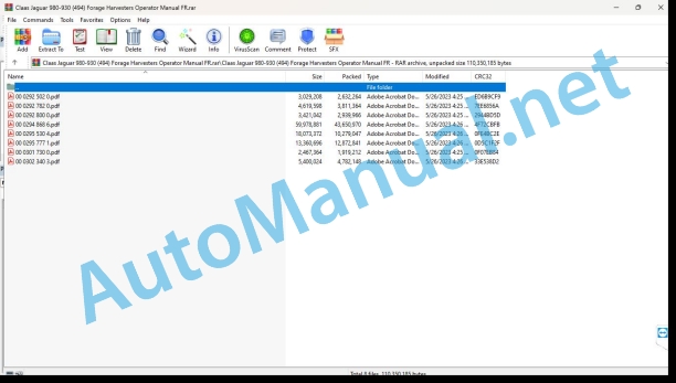
00 0292 502 0.pdf
00 0292 782 0.pdf
00 0292 800 0.pdf
00 0294 868 6.pdf
00 0295 530 4.pdf
00 0295 777 1.pdf
00 0301 730 0.pdf
00 0302 340 3.pdf
00 0292 502 0.pdf:
Contents
Introduction
Information about this notice
Validity of the notice
Maintenance
Disconnect the machine and secure it
Disconnect the machine and secure it
Eliminate crop flow malfunction
Resolve crop flow failures
00 0292 782 0.pdf:
JAGUAR 980 – 930
Contents
About this user manual
General informations
Validity of the notice
Security
Important
Marking of warnings and dangers
Preparing the machine
Disconnect the machine and secure it
Disconnect the machine and secure it
Corn cracker (optional equipment)
Place the corn cracker (optional equipment)
Set corn-cracker pattern
CEBIS use
Sharpen/counterblade menu
Maintenance
Power group
Adjust the feed drum under the scraper
Adjust the V-MAX chopper knives
Align the counterblade
Replace the V-MAX chopper knives
Adjust the basic setting of the bedknife
Remove/install the counterblade
00 0292 800 0.pdf:
JAGUAR 980 – 930
Contents
1 About this user manual
1.1 General information
1.1.1 Validity of the notice
2 Preparing the machine
2.1 Disconnect the machine and secure it
2.1.1 Disconnect the machine and secure it
2.2 Discharge
2.2.1 Install the HD ejector elbow extension
3 Maintenance
3.1 Hash
3.1.1 Replace the V-MAX chopper knives
00 0295 530 4.pdf:
JAGUAR 980 – 930
Contents
About this user manual
General informations
Validity of the notice
Controls and displays
Cabin / Driving position
Overview of the driving position
Control console (up to machine no….)
Control console (from machine No.: …)
Cab roof control elements (up to machine no. …)
Cab roof control elements (from machine no. …)
Control elements column B (up to machine No….)
Control elements column B (from machine No. …)
Advancement lever
Multifunction handle
Driving informant
Multifunction switch
TELE CAM screen (additional equipment)
Control elements and display
Control console and on-board information system
Travel indicator
Harvest indicator
Direct menu CEBIS switch
Direct menu HOTKEY switch
CEBIS error types
Message box symbols
Road driving and transportation
Prepare for road travel
Prepare to move into the field
Park the machine
Maneuvers with the machine
Start work
CEBIS use
CEBIS general advice
Validity
Main Menu
Front Tool Menu
Driving menu
AUTO PILOT menu
Chop Menu
Sharpen/counterblade menu
Performance Measurement Menu
Counter Menu
Maintenance/Diagnostic Menu
CEBIS Menu
Adjusting the diesel engine speed
DYNAMIC POWER
Connect DYNAMIC POWER
Activate diesel engine
Disconnect the diesel engine
Check the brake pressure switch
Activate the parking brake
Disconnect the parking brake
Brake the machine using the forward lever
Brake the machine using the foot brake
Submit a report
POWER TRAC (optional equipment)
Connect POWER TRAC (optional equipment)
Disconnect POWER TRAC (optional equipment)
Switch on the automatic cruise control (Tempomat, additional equipment)
Switching off automatic cruise control (Tempomat, additional equipment)
AUTO PILOT (additional equipment)
Setting the AUTO PILOT (additional equipment)
Connecting the AUTO PILOT (additional equipment)
Disconnect the AUTO PILOT (additional equipment)
Connecting the tire pressure regulator (additional equipment)
Disconnecting the tire pressure regulator (additional equipment)
Hydraulic system
Oscillation damping
Switching on oscillation damping
Ground guidance
Select ground guidance
Cutting height regulation
Connect cutting height regulation
Save the cutting height regulation value
Disconnect cutting height regulation
Cutting height preselection
Activate cutting height preselection
Memorize the cutting height preset value
Disconnect cutting height preselection
Adjust AUTO CONTOUR sensitivity
Power group
Learn the zero point of performance measurement
Connect the power group
Disconnect the power group
Connect inversion
Chopping bodies
Disable Hash Bodies
Adjusting the chopper cutting length
Sharpening the chopper knives
Electric adjustment of the gap between the corn cracker rollers (optional equipment)
Electric adjustment of the discharge accelerator drum gap dimension (optional equipment)
Ejector elbow
Raising the ejector elbow
Pivoting of the ejector elbow
Lowering of the ejector elbow
Park the ejector elbow (additional equipment)
Activate automatic swivel of the ejector elbow (additional equipment)
Automatic pivoting of the ejector elbow (additional equipment) memorize the pivoting position
Connect OPTI FILL
Disconnect OPTI FILL
Activate silage additive device
Disconnect the silage additive system
AUTO FILL (additional equipment)
Set AUTO FILL
Connect AUTO FILL
Position the transport trailer
AUTO FILL camera (additional equipment)
Disconnect AUTO FILL
00 0295 777 1.pdf:
Contents
1 Introduction
1.1 General advice
1.1.1 Use of the instructions
1.1.2 Validity of the notice
1.1.3 Technical information
1.2 Nameplates and identification numbers
1.2.1 Spare parts and technical questions
1.2.2 Nameplate
2 Safety Tips
2.1 General advice
2.1.1 Important
2.1.2 Conformity of use
2.2 Safety information
2.2.1 Marking of warnings and dangers
2.3 Warning pictograms
2.3.1 General advice regarding warning pictograms
2.3.2 Adapter
3 pieces supplied
3.1 LEXION front tool adapter
3.1.1 Retrofit clearance
4 Assembly
4.1 Prepare the installation
4.1.1 Turn off the machine
4.1.2 Check the parts provided
4.2 Assembly of machine equipment
4.2.1 Installing the hydraulic system (JAGUAR types 492/493 only)
4.2.2 Installation of the electrical system (only JAGUAR types 492/493)
4.2.3 Installation of the electrical system (JAGUAR type 494 only)
4.2.4 Shorten the PTO adapter (only JAGUAR type 493/494)
4.2.5 Preassemble the multicoupling
4.2.6 Install the reel peripheral speed cable set (cutting deck only, only for types 492/493)
4.2.7 Prepare a test operation and carry it out
5 Technical characteristics
5.1 JAGUAR – LEXION front tool adapter – TYPES 492 / 493 / 494
5.1.1 Dimensions
5.1.2 Weight
5.1.3 Acceptable front-end tools
6 Before first commissioning
6.1 General advice
6.1.1 General warnings Before initial commissioning
6.1.2 Checklist for initial commissioning
7 Before each commissioning
7.1 General advice
7.1.1 General warnings Before each commissioning
7.1.2 Commissioning checklist
8 Mount/dismount the front tool
8.1 General advice
8.1.1 General warnings place/remove the front tool
8.2 Mounting the adapter
8.2.1 Connect the cable set (JAGUAR type 494 only)
8.2.2 Remove the quick coupling (JAGUAR types 493/494 only)
8.2.3 Mounting the adapter
8.3 Install the front tool
8.3.1 Install CONSPEED
8.3.2 Install the cutting deck (folding)
8.4 Remove the adapter
8.4.1 Disconnect the cable set (JAGUAR type 494 only)
8.4.2 Remove the adapter
8.4.3 Install the quick coupling (JAGUAR types 493/494 only)
9.1 General advice
9.1.1 General work warning advice
9.2 Cabin / driving position
9.2.1 Control elements
10 Incidents and remedy
10.1 General advice
10.1.1 General warning tips Fault and solution
10.2 Attached parts / machine casing
10.2.1 Setting the lock
11 Maintenance
11.1 General advice
11.1.1 General warning advice Maintenance
11.2 General maintenance information
11.2.1 Fixing material
11.2.2 Post-harvest maintenance work
11.2.3 Tightening torque for metric adjustment thread
11.2.4 Tightening torques for fine metric threads
11.2.5 Tightening torques for hydraulic connections with cutting ring DIN 3861
11.2.6 Tightening torques for hydraulic connections and air conditioning connections with bicone ring and O-ring DIN 3865
11.3 Maintenance table
11.3.1 Maintenance frequencies
11.4 Lubricant table
11.4.1 Lubricants
11.5 Gearbox / Clutch
11.5.1 Check transmission gearbox oil level
11.5.2 Pour oil into the transmission gearbox
11.5.3 Change transmission gearbox oil
11.5.4 Check output gearbox oil level
11.5.5 Pour oil into the output gearbox
11.5.6 Change output gearbox oil
12 Lubrication plan
12.1 General advice
12.1.1 General warning tips lubrication scheme
12.2 Lubrication points
12.2.1 Lubrication intervals
12.2.2 Lubrication points – 100 h
Alphabetical index
00 0301 730 0.pdf:
IIIB diesel engines
Contents
1.1 Diesel engine
1.1.1 Connect the diesel engine
EN – Connect the diesel engine
No significant engine error recognized (DTC)
Engine Recognized Significant Error (DTC)
00 0302 340 3.pdf:
JAGUAR 990 /980 / 970 / 960 / 950 / 940 / 930JAGUAR 880 / 870 / 860 / 850 / 840 / 830JAGUAR 990 / 960 TERRA TRAC
Contents
1 Introduction
1.1 General instructions
1.1.1 Validity of the notice
1.1.2 Information about this user manual
1.1.3 Icons and notes
1.1.4 Notes on maintenance
1.1.5 Notes regarding warranty
1.1.6 Spare parts and technical questions
1.2 Nameplates and identification numbers
1.2.1 Adapter nameplate
2 Security
2.1 Recognize the warnings
2.1.1 Warning pictogram
2.1.2 Signal word
2.2 Safety tips
2.2.1 Meaning of the instructions for use
2.2.2 Observe warning pictograms and warning advice
2.2.3 Requirements for all people who work with the product
2.2.4 Couple the machine with the front tool
2.2.5 Risk of injury to the cardan shaft
2.2.6 Constructive modifications
2.2.7 Technical condition
2.2.8 Inappropriate operating consumables
2.2.9 Environmental protection and disposal
2.2.10 Liquids under pressure
2.3 Safety label
2.3.1 Structure of warning pictograms
2.3.2 Warning pictogram on the adapter
3 Control and display elements
3.1 Cabin and driving position
3.1.1 Control elements on column B
4 Technical characteristics
4.1 Adapter
4.1.1 Authorized machines
4.1.2 Dimensions
4.1.3 Weight
4.1.4 Lubricants
5.1 Adapter
5.1.1 Using the adapter
5.1.2 Remove the scraper bars
5.1.3 Adjust the speed of the feed drum
5.1.4 Adjust the cutting height
5.1.5 Adjust the interconnection
5.1.6 Mounting the adapter
5.1.7 Remove the adapter
6 Maintenance
6.1 Overview of maintenance frequencies
6.1.1 Every 10 operating hours or every day
6.1.2 Every 100 operating hours
6.1.3 Every 500 operating hours or every year
6.2 Lubrication plan
6.2.1 Lubricate the lubrication points every 10 hours of operation
6.2.2 Lubricate the lubrication points every 100 operating hours
6.3 Transmission, clutch and cardan shaft
6.3.1 Checking the oil level of the drive gearbox
6.3.2 Change the oil from the drive gearbox
Change the oil
Fill with oil
6.3.3 Check the output gearbox oil level
6.3.4 Change output gearbox oil
Drain the oil
Pour the oil
6.3.5 Check the chain tension
John Deere Repair Technical Manual PDF
John Deere PowerTech M 10.5 L and 12.5 L Diesel Engines COMPONENT TECHNICAL MANUAL CTM100 10MAY11
John Deere Repair Technical Manual PDF
John Deere Repair Technical Manual PDF
John Deere Repair Technical Manual PDF
John Deere 18-Speed PST Repair Manual Component Technical Manual CTM168 10DEC07
John Deere Parts Catalog PDF
John Deere Harvesters 8500 and 8700 Parts Catalog CPCQ24910 Spanish
John Deere Repair Technical Manual PDF
John Deere Repair Technical Manual PDF
John Deere Parts Catalog PDF
John Deere Tractors 7500 Parts Catalog CPCQ26568 30 Jan 02 Portuguese
John Deere Repair Technical Manual PDF
John Deere Repair Technical Manual PDF

