Claas Jaguar 980-930 (498) Forage Harvesters Technical System FR
$150.00
- Model: Jaguar 980-930 (498) Forage Harvesters
- Type Of Manual: Technical System
- Language: FR
- Format: PDF(s)
- Size: 228 MB
File List:
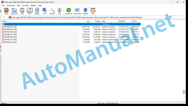
00 0288 553 5.pdf
00 0288 930 1.pdf
00 0291 028 2.pdf
00 0296 327 2.pdf
00 0298 056 3.pdf
00 0303 171 0.pdf
00 0303 625 1.pdf
00 0288 930 1.pdf:
MAN D2862-V12 Tier 4LE 133LE 134
Contents
Introduction
Safety tips
Safety instructions and dangers
Validity of the notice
Validity of the notice
Security
General instructions
Marking of warnings and dangers
Safety Routines
First aid measures
CCN explanation
CCN (CLAAS Component Number – CLAAS part number)
CCN (CLAAS Component Number – CLAAS part number)
01 Motor
0102 Complete set
Flame Starter Relay (A1154-MAN)
Connector allocation
Connector A
Connector B
0125 Injection system, fuel supply
System Description
Schematic structure of the Common Rail system
Schematic structure of the SCR dosing system
High pressure pump
High pressure pump CP3.4
ZME Unit of Measurement (Y332-MAN)
Pin assignment
High pressure accumulator (Rail)
Pressure limiter
Rail Pressure Sensor (B487-MAN, B514-MAN)
Connector allocation
Injector (Y341-MAN – Y352-MAN)
Fuel Temperature Sensor (B197-MAN)
Connector allocation
Connection diagram
Fuel pre-filter water level sensor
Connector allocation
0135 Cooling system
Make-up tank coolant level sensor
Connector allocation
0140 Exhaust device
Exhaust Gas Temperature Sensor After SCR Catalyst (B634-MAN)
Connector allocation
0155 Engine controls
EDC17 control unit (A435-MAN)
Pin allocation of the EDC17 control unit
Control unit connector A
Control unit connector B
Control unit connector C
Control device connector D
Crankshaft Sensor (Incremental RPM Sensor) (B488-MAN)
Connector allocation
Connection diagram
Camshaft Sensor (Segmented RPM Sensor) (B489-MAN)
Connector allocation
Connection diagram
Oil Pressure Sensor (B104-MAN)
Sensor characteristic curve
Connector allocation
Oil Level Sensor and Oil Temperature Sensor (B270-MAN)
Connector allocation
Fuel Pressure Sensor (B377-MAN)
Sensor characteristic curve
Connector allocation
Air Mass Measuring Device (B323-MAN)
Connector allocation
Intake Pressure Sensor (B623-MAN)
Connector allocation
Coolant Temperature Sensor (B124-MAN)
Connector allocation
Connection diagram
0165 Exhaust gas aftertreatment
Post-treatment of exhaust gases
Graphical representation of the V-motor system with SCR
Exhaust Gas Thermocouples (A1191-MAN)
Connector allocation
Lambda probe (B322-MAN)
Connector allocation
Power Module (A808-MAN)
Connector allocation
Dosing module (A1279-MAN)
Connector allocation
Tank Heater Valve (Y437-MAN)
Connector allocation
AdBlue® Combination Transmitter (A1192-MAN)
Connector allocation
NOx Sensor I (gross emission) (B1055-MAN)
Connector allocation
NOxI sensor (diagnostic) (B994-MAN)
Connector allocation
10 Electrical/electronic system
1080 Electrical connection plan
Electrical connection diagram of the EDC17 measuring device
1085 Network functions
CAN bus and power supply overview
90 Others
9090 Diagnosis
HD-OBD diagnostic socket (X200-MAN)
Error logging
CDS error display
FMI (Failure Mode Identification)
List of steps for checking the EDC17 control unit
1. Measurements on the EDC17 motor control device
Troubleshooting the high pressure system
Check leak volume
Measurement of overall leak volume
Preparations
Block diagram of the measurement structure
Checking the various injectors for leaks
Measure the flow rate of the high pressure pump
Acceleration test
Description
Compression test
Description
Cylinder Disconnect Test
Description
Acceleration test
Description
Injector test
Description
Reset pressure relief valve
Description
Pressure limiter test
Description
SCR dosage quantity test
Description
Reset SCR system errors
Description
System test of the SCR dosing system
Description
Reset the incentive counter
Description
CP3.4 D2862 Oil Lubricated High Pressure Pump Fuel Schematic
D2862 Engine Fuel Diagram – LE13x
Troubleshooting the CAN connection
1. Master NOx I sensor (gross emission)
2. Master NOx II sensor (diagnostic)
3. Master thermocouples
4. Master AdBlue® combined transmitter
5. NOx sensor I (gross emission) slave
6. NOx II sensor (diagnostic) slave
7. Slave thermocouples
Diagnostic program
Troubleshooting in the SCR dosing system
General overview
RPM plausibility/blocked pump
Leaking suction line
Return blocked
SPN 98 – FMI 1: engine oil level too high
SPN 98 – FMI 2: engine oil level too low
SPN 98 – FMI 3: implausibl egine oil level
SPN 100 – FMI 1: engine oil pressure too high
SPN 100 – FMI 2: engine oil pressure too low
SPN 168 – FMI 6: battery voltage short circuit
SPN 3004 – FMI 4: EGR valve blocked
SPN 3014 – FMI 3: signal from control devices – main relay implausible
SPN 3082 – FMI 1: oil pressure sensor signal too high
SPN 3082 – FMI 2: oil pressure sensor signal too low
SPN 3083 – FMI 1: Rail pressure sensor signal too high
SPN 3083 – FMI 2: rail pressure sensor signal too low
SPN 3083 – FMI 3: implausible rail pressure sensor signal
SPN 3752 – FMI 4: camshaft sensor signal missing
SPN 3752 – FMI 5: camshaft sensor – short circuit to ground
SPN 3752 – FMI 6: camshaft sensor – short circuit to plus
SPN 3753 – FMI 4: crankshaft sensor signal missing
SPN 3753 – FMI 5: crankshaft sensor – short circuit to ground
SPN 3753 – FMI 6: crankshaft sensor – short circuit to plus
SPN 3753 – FMI 8: crankshaft sensor – incorrect signal
SPN 3753 – FMI 10: crankshaft sensor – breakage
SPN 3775 – FMI 1: rail pressure too high
SPN 3775 – FMI 2: rail pressure too low
SPN 3776 – FMI 1: positive rail pressure regulation difference
SPN 3778 – FMI 1: rail pressure leak under thrust conditions
SPN 3780 – FMI 1: rail pressure leak at idle
SPN 3781 – FMI 1: pressure limiter open
SPN 3797 – FMI 5: heating of the Lambda probe – short circuit to ground
SPN 3797 – FMI 6: Lambda sensor heating – short circuit to plus
SPN 3797 – FMI 10: heating of the Lambda probe – breakage
SPN 3847 – FMI 4: Intake Pressure Sensor/Temperature Sensor Signal Missing
SPN 3847 – FMI 5: Intake Pressure Sensor/Temperature Sensor – Short to Ground
SPN 3847 – FMI 6: Intake Pressure Sensor/Temperature Sensor – Short to Plus
SPN 3847 – FMI 10: manifold pressure sensor/temperature sensor – rupture
SPN 3847 – FMI 11: intake pressure sensor/temperature sensor – false contact
SPN 3855 – FMI 5: Lambda probe sensor cables – short to ground
SPN 3855 – FMI 6: Lambda probe sensor cables – short circuit to plus
SPN 3856 – FMI 1: Lambda probe calibration too high
SPN 3856 – FMI 2: Lambda probe calibration too low
SPN 3857 – FMI 3: implausible values of the Lambda probe evaluation unit
SPN 3858 – FMI 1: Lambda probe temperature too high
SPN 3858 – FMI 2: Lambda probe temperature too low
SPN 3859 – FMI 1: Lambda probe temperature calibration too high
SPN 3859 – FMI 2: Lambda probe temperature calibration is too low
SPN 4400 – FMI 9: failure to defrost the AdBlue® system (hardware failure)
SPN 6140 – FMI 5: airless dosing system (pressure sensor) – short circuit after ground
SPN 6140 – FMI 6: airless dosing system (pressure sensor) – short circuit (UBat)
SPN 6140 – FMI 11: airless dosing system (pressure sensor) – (false contact)
SPN 6142 – FMI 5: airless dosing system (temperature sensor) – short circuit after ground
SPN 6142 – FMI 6: airless dosing system (temperature sensor) – short circuit after 6142 – FMI 11: airless dosing system (temperature sensor) – false contact
SPN 6143 – FMI 6: urea dosing valve – short circuit after UBat
SPN 6143 – FMI 7: urea dosing valve – short circuit
SPN 6143 – FMI 12: urea dosing valve – short circuit after UBat or interruption
SPN 6143 – FMI 13: urea dosing valve – short circuit to ground or interruption
SPN 6151 – FMI 2: PTC final stage
SPN 6151 – FMI 5: PTC final stage – short circuit (ground)
SPN 6151 – FMI 6: PTC final stage – short circuit (UBat)
SPN 6151 – FMI 10: PTC final stage – interruption (Open Load)
SPN 6161 – FMI 1: SCR pump blocked
SPN 6161 – FMI 2: correlation of pressure and speed of the SCR pump
SPN 6163 – FMI 1: correlation of pressure and speed of the SCR pump on the service routine
SPN 6163 – FMI 2: correlation of pressure and speed of the SCR pump on the service routine
SPN 6163 – FMI 3: correlation of pressure and speed of the SCR pump on the service routine
SPN 6164 – FMI 9: hardware failure of the dosing unit
SPN 6165 – FMI 3: correlation of pressure and speed of the SCR pump
SPN 6166 – FMI 1: SCR pump speed
SPN 6166 – FMI 3: SCR pump speed
SPN 6170 – FMI 9: hardware failure of the SCR pump
SPN 6171 – FMI 1: replace the SCR pump filter
SPN 6172 – FMI 1: the SCR pump filter is full
SPN 6197 – FMI 5: airless dosing system (speed feedback message)
SPN 6197 – FMI 6: airless dosing system (speed feedback message)
SPN 6207 – FMI 1: final stage of the urea dosing pump
SPN 6207 – FMI 5: final stage of the urea dosing pump – short circuit after ground
SPN 6207 – FMI 6: final stage of the urea dosing pump – short circuit after UBat
SPN 6207 – FMI 10: final stage of the urea dosing pump – interruption
SPN 6212 – FMI 9: failure to defrost the AdBlue® system – hardware failure
Location of parts
Electrical system
A435-MAN Engine management module
Component
Mounting points
High pressure pump
Component
Mount point
Unit f measurement (ZME)
Component
Mount point
High pressure accumulator (Rail)
Component
Mount point
Pressure limiter
Component
Mount point
B487-MAN Rail pressure sensor
Component
Mount point
Y341-MAN Injector 1
Component
Mount point
B488-MAN Crankshaft sensor (incremental speed sensor)
Component
Mount point
B489-MAN Camshaft sensor (segmented speed sensor)
Component
Mount point
Oil Level Sensor and Oil Temperature Sensor (B270-MAN)
Component
Mount point
B377-MAN Fuel Pressure Sensor
Component
Mount point
B323-MAN Air mass measuring device
Component
Mount point
B104-MAN Oil pressure sensor
Component
Mount point
B623-MAN Intake Pressure Sensor/Temperature Sensor
Component
Mount point
B124-MAN Coolant Temperature Sensor
Component
Mount point
B197-MAN Fuel Temperature Sensor
Component
Mount point
Oil temperature sensor
Component
Mount point
B634-MAN Exhaust gas temperature sensor after SCR catalyst
Component
Mount point
A1191-MAN Exhaust Gas Thermocouples
Component
Mount point
B322-MAN Lambda Probe
Component
Mount point
A808-MAN Power module
Component
Mount point
A1279-MAN Dosing module
Component
Mount point
Y437-MAN Tank Heating Valve
Component
Mount point
A1192-MAN AdBlue® Combination Transmitter
Component
Mount point
B1055-MAN NOx I sensor (gross emission)
Component
Mount point
B994-MAN NOx II sensor (diagnostic)
Component
Mount point
A1154-MAN Flame Starter Relay
Component
Mount point
00 0291 028 2.pdf:
MB OM460LAMB OM502LAMB OM906LAMB OM926LA
Contents
CCN explanation
CCN (CLAAS Component Number – CLAAS part numbe)
Electrical standard
Overview
Hydraulic standard Overview
CCN (CLAAS Component Number – CLAAS part number)
Introduction
Safety tips
Safety instructions and risk information
Validity of the notice
Validity of the notice
01 Motor
0125 Injection system, fuel supply
PLD Injection/Fuel System
PLD injection system
Function description
Plug-in pump power phases
Function description
Plug-in pump control
Function description
Classification of plug-in pumps
Example of plug-in pump nameplate
Coding, example of plug-in pump nameplate
Low fuel pressure measurement
Special tool
Preparing for low fuel pressure measurement
Function description
Measured values, low fuel pressure (after fuel filter)
0155 Engine controls
Diesel engine monitoring, diesel engine (MB TIER 3) TUCANO, JAGUAR
Measurement value table
Function description
Diesel engine monitoring, diesel engine (MB TIER 3) LEXION
Measurement value table
Function description
Diesel engine monitoring, diesel engine (MB TIER 4i) TUCANO, JAGUAR
Measurement value table
Function description
Torque limitation in case of urea shortage
Function description
Torque limitation in case of lack of urea quality
Function description
Torque limitation in case of time exceeded with system errors
Function description
Diesel engine monitoring, diesel engine (MB TIER 4i) LEXION
Measurement value table
Function description
Torque limitation in case of urea shortage
Function description
Torque limitation in case of lack of urea quality
Function description
Torque limitation in case of time exceeded with system errors
Function description
0165 Exhaust gas aftertreatment
MB TIER 4i compressed air system (LEXION, TUCANO)
Function description
Air dryer with integrated pressure regulator
Function description
Compressed air system MB TIER 4i (JAGUAR)
Function description
Air dryer with integrated pressure regulator
Function description
SCR system – Urea heating and injection
Function description
Combined filling level / urea temperature sensor
Function description
Urea pump unit
Function description
Reduction Catalyst Temperature Sensors
Function description
Dosing unit
Function description
NOx sensor
Function description
Combined sensor for intake air humidity and temperature
Function description
10 Electrical/electronic system
1012 Modules – Sensors
Module overview – MB (OM460LA, 502LA, 906LA, 926LA)
Designations
Module A015 – electronic engine management (ECM) – MB TIER 4i
Connector X1
Designations
Module allocation, connector X1
Connector X2, plug 1 of 2, inline 6 and V8 engine
Module allocation, connector X2 plug 1 of 2
Connector X2, plug 2 of 2, motor in line 6
Module allocation, connector X2 plug 2 of 2, motor in line 6
Connector X2, plug 2 of 2, V8 engine
Module allocation, connector X2, plug 2 of 2, V8 engine
Module A017 – Engine adaptation (ADM) – MB TIER 3
Designations
Designations
Module A017 – Engine adaptation (ADM) – MB TIER 4i
Designations
Designations
Module A032 – Reduction catalyst (SCR) – MB TIER4i
Designations
Designations
MB OM460LA sensors
Illustration of sensors
MB 502LA sensors
Illustration of sensors
MB sensors OM 906LA, OM 926LA
Illustration of sensors
1085 Network functions
BUS (CAN) system – Motor and machine
Function description
92 Diagnosis
Diagnosis according to error codes
9220 Diesel Engine Error Codes (J1939)
FMI (Failure Mode Indicator) error code
FMI (Failure Mode Indicator) error code
FMI 00 (Signal too large)
FMI 01 (signal too small)
IMF 02 (Implausible signal)
FMI 03 (voltage too high)
FMI 04 (voltage too low)
FMI 05 (current too low)
FMI 06 (current too high)
FMI 07 (mechanical error)
FMI 08 (frequency signal defective)
FMI 09 (communication error)
FMI 10 (signal modification too fast)
FMI 11 (multiple error)
FMI 12 (ECU faulty)
FMI 13 (signal outside calibration range)
FMI 16 (non-existent parameter)
FMI 17 (ECU not responding)
FMI 18 (voltage supply error)
FMI 19 (software conditions not met)
FMI 95 (no signal modification)
FMI 96 (CAN-bus system defective)
IMF 97 (implausible state)
IMF 98 (alarm)
IMF 99 (News)
Error Codes
J1939 Diesel Engine Error Code List (MB)
Function description
00 0296 327 2.pdf:
MAN D2868MAN D2862
Contents
CCN explanation
CCN (CLAAS Component Number – CLAAS part number)
CCN (CLAAS Component Number – CLAAS part number)
Introduction
Safety tips
Safety instructions and dangers
Validity of the notice
Validity of the notice
01 Motor
0125 Injection system, fuel supply
System Description
Schematic structure of the Common Rail system
High pressure pump
High pressure pump CP3.4 / CP3.4+
ZME Measuring Unit (MProp Fuel Proportional Valve) (Y332-MAN, Y356-MAN)
Connector allocation
High pressure accumulator (Rail)
Pressure limiter
Rail Pressure Sensor (B487-MAN, B514-MAN)
Sensor characteristic curve
Connector allocation
Injector (Y341-MAN, Y350-MAN)
Fuel Temperature Sensor (B197-MAN)
Connector allocation
Connection diagram
0140 Exhaust device
Exhaust Gas Temperature Sensor (B633-MAN)
Connector allocation
0155 Engine controls
EDC7 control unit (A435-MAN, A570-MAN)
EDC7 C32 Master CE Level IIIB/Tier 4i V8 Control Unit (A435-MAN) Motor Connector Pin Allocation A
EDC7 C32 Master CE Level IIIB/Tier 4i V8 Control Unit (A435-MAN) Vehicle Connector Pin Allocation B
EDC7 C32 Master CE Level IIIB/Tier 4i V8 Control Unit (A435-MAN) Injector Connector Pin Allocation C
EDC7 C32 Slave CE Level IIIB/Tier 4i V8 Control Unit (A570-MAN) Motor A Connector Pin Allocation
EDC7 C32 Slave CE Level IIIB/Tier 4i V8 Control Unit (A570-MAN) Vehicle B Connector Pin Allocation
EDC7 C32 Slave CE Level IIIB/Tier 4i V8 Control Unit (A570-MAN) Injector Connector Pin Allocation C
Crankshaft RPM Sensor (Incremental RPM Sensor) (B488-MAN)
Connector allocation
Connection diagram
Camshaft RPM Sensor (Rpm Segmentation Sensor) (B489-MAN)
Connector allocation
Connection diagram
Oil Pressure Sensor (B104-MAN)
Sensor characteristic curve
Connector allocation
Fuel Pressure Sensor (B377-MAN)
Sensor characteristic curve
Connector allocation
Bosch LDF 6T Intake Pressure Sensor (B623-MAN)
Connector allocation
Coolant Temperature Sensor (B124-MAN)
Connector allocation
Connection diagram
10 Electrical/electronic system
1080 Electrical connection plan
Quick view EDC7 (D2862-V12)
Quick view EDC7 (V8)
Quick view EDC7 (R6)
Quick overview of the DCU15 power module (V-motors)
Quick overview of the DCU15 power module (in-line motor)
90 Others
9090 Diagnosis
System structure of K cables, diagnostic sockets
Diagnostic socket (X200-MAN)
HD-OBD diagnostic socket (X200-MAN)
Error logging
CDS error display
FMI (Failure Mode Identification)
EDC 7 SPN List (C32)
List of EDC7 C32 check steps (6-cylinder engine)
Check step list EDC7 C32 CE level IIIB/Tier 4i (6-cylinder engine)
1. Measurements on the EDC7 C32 engine management device
Check Step List EDC7 C32 Master-Slave CE Level IIIB/Tier 4i (8-Cylinder V-Engine)
1. Measurements on the EDC7 C32 engine management device
Hydraulic Checklist
Fundamentals of Error Detection
Catalog of questions in case of problems
Common errors and tips for solving them
General notes on troubleshooting in the fuel industry
Troubleshooting the low pressure system
Troubleshooting the high pressure system
Check leak volume
Measurement of overall leak volume
Preparations
Principle representation of the measurement structure
Checking the various injectors for leaks
High pressure pump flow measurement
Troubleshooting with CDS
Compression test
Acceleration test
Cylinder Disconnect Test
Acceleration test
General fuel diagram of CP3.4 D2868 oil lubricated high pressure pump
CP3.4 D2862 Oil Lubricated High Pressure Pump Fuel Schematic
D2868 Euro 4/5 engine fuel diagram
D2862 Euro 4/5 engine fuel diagram
Troubleshooting plan
Diagnostic program
SPN 94 FUEL SUPPLY PRESSURE
SPN 100 physical OIL PRESSURE
SPN 102 INTAKE PRESSURE AFTER RADIATOR (charge air pipe) physical
SPN 105 CHARGE AIR TEMPERATURE BEFORE CYLINDER INTAKE (after EGR) physical
SPN 108 physical ATMOSPHERIC PRESSURE
SPN 110 Physical COOLANT TEMPERATURE
SPN 168 BATTERY VOLTAGE
SPN 171 ROOM TEMPERATURE physical
SPN 173 EXHAUST GAS TEMPERATURE BEFORE PHYSICAL EXHAUST GAS AFTERTREATMENT
SPN 174 physical FUEL TEMPERATURE
SPN 190 ENGINE SPEED
Oscilloscope curves
SPN 609 CAN 1 MODULE
SPN 651 BANK 1 INJECTOR 1 (6-cylinder engine: cylinder 1; 8-cylinder engine master: Cylinder 1, slave: cylinder 5; 12-cylinder engine master: cylinder 1, slave: cylinder 12)
SPN 652 BANK 2 INJECTOR 1 (6-cylinder engine: cylinder 5; 8-cylinder engine master: Cylinder 2, slave: cylinder 7; 12-cylinder engine master: cylinder 2, slave: cylinder 11)
SPN 653 BANK 1 INJECTOR 2 (6-cylinder engine: cylinder 3; 8-cylinder engine master: Cylinder 3, slave: cylinder 6; 12-cylinder engine master: cylinder 3, slave: cylinder 10)
SPN 654 BANK 2 INJECTOR 2 (6-cylinder engine: cylinder 6; 8-cylinder engine master: Cylinder 4, slave: cylinder 8; 12-cylinder engine master: cylinder 6, slave: cylinder 7)
SPN 655 BANK 1 INJECTOR 3 (6-cylinder engine: cylinder 2; 12-cylinder engine master: Cylinder 5, slave: cylinder 8)
SPN 656 BANK 2 INJECTOR 3 (6-cylinder engine: cylinder 4; 12-cylinder engine master: Cylinder 4, slave: cylinder 9)
SPN 1079 RAIL PRESSURE SENSOR POWER SUPPLY
SPN 1080 POWER SUPPLY TO LOW FUEL PRESSURE SENSOR, INTAKE PRESSURE SENSOR, OIL PRESSURE SENSOR, EXHAUST GAS RELATIVE PRESSURE SENSOR
SPN 1131 CHARGE AIR TEMPERATURE AFTER RADIATOR (in charge air pipe) physical
SPN 3004 EGR ACTUATOR PERMANENT REGULATION GAP
SPN 3007 INVALID DM4 REQUEST
SPN 3009 ENGINE OVERSPEED
SPN 3014 MAIN RELAY CONNECTED
SPN 3046 ATMOSPHERIC PRESSURE SENSOR
SPN 3063 INERTIA OPERATION NOT COMPLETED
SPN 3064 EDC STAND-ALONE SERVICE
SPN 3069 REDUNDANT RPM MONITORING
SPN 3076 START LOCK UNLOCK
SPN 3077 START LOCK UNLOCK
SPN 3082 LIKELIHOOD OF OIL PRESSURE SENSOR
SPN 3083 LIKELIHOOD OF RAIL PRESSURE SENSOR
SPN 3087 OIL PRESSURE SENSOR
SPN 3088 INTAKE PRESSURE SENSOR AFTER RADIATOR (in charge air pipe)
SPN 3089 CHARGE AIR TEMPERATURE SENSOR BEFORE CYLINDER INLET (after EGR)
SPN 3091 COOLANT TEMPERATURE SENSOR
SPN 3097 FUEL TEMPERATURE SENSOR
SPN 3099 RAIL PRESSURE SENSOR
Sensor characteristic curve
SPN 3100 FUEL PRESSURE SENSOR (LOW PRESSURE)
SPN 3671 ERROR LOADING EEPROM
SPN 3673 CAN MODULE 2 (CAN OBD or CAN master-slave)
SPN 3676 REDUNDANT FAILED SHUTDOWN DEVICE (INERTIA OPERATION MODE TEST)
SPN 3678 CAPACITOR BANK OVERAMPLIFICATION VOLTAGE 1
SPN 3679 CAPACITOR BANK OVERAMPLIFICATION VOLTAGE 2
SPN 3687 PRESSURE LIMITER DOES NOT OPEN
SPN 3732 FAULTY CLASSIFICATION FOR INITIALIZATION
SPN 3735 INTERNAL TEMPERATURE EDC
SPN 3736 END STAGE DISCONNECTION BY EDC EQUIPMENT
SPN 3746 FINAL STAGE HIGHSIDE EXHAUST GAS RECIRCULATION
SPN 3748 FINAL FLOOR HIGHSIDE MEASUREMENT UNIT
SPN 3751 FINAL STAGE HIGHSIDE STARTER RELAY (IMR)
SPN 3752 CAMSHAFT RPM SENSOR (SEGMENT SENSOR)
SPN 3753 CRANKSHAFT SPEED SENSOR (INCREMENTAL SENSOR)
Crankshaft speed sensor signal measured at 600 rpm between pin A73 and A55
SPN 3754 SYSTEM STARTUP WATCHDOG ERROR
SPN 3755 LIKELIHOOD OF LOW FUEL PRESSURE
SPN 3756 SUPPLY VOLTAGE EGR RECEIPT CONFIRMATION
SPN 3773 MASTER/SLAVE SERVICE MODE CHANGE ERROR
SPN 3775 RAIL PRESSURE MONITORING
SPN 3776 POSITIVE RAIL PRESSURE REGULATION DIFFERENCE
SPN 3777 NEGATIVE RAIL PRESSURE REGULATION DIFFERENCE
SPN 3778 RAIL PRESSURE: LEAK UNDER THRUST CONDITIONS
SPN 3779 RAIL PRESSURE: LEAK DUE TO QUANTITY COMPENSATION
SPN 3780 RAIL PRESSURE: HIGH REGULATOR OUTPUT AT IDLE
SPN 3781 OPEN PRESSURE LIMITER
SPN 3782 DYNAMIC FUEL SUPPLY PRESSURE
SPN 3785 MONITORING THE PARTICLE FILTER/PM-CAT
SPN 3786 PARTICLE FILTER TEMPERATURE LIMITS
SPN 3789 DIFFERENTIAL OR RELATIVE EXHAUST GAS PRESSURE SENSOR
SPN 3790 LIKELIHOOD OF DIFFERENTIAL OR RELATIVE EXHAUST GAS PRESSURE
SPN 3792 EXHAUST GAS TEMPERATURE SENSOR BEFORE EXHAUST GAS AFTERTREATMENT
SPN 3793 EXHAUST GAS TEMPERATURE SENSOR AFTER PHYSICAL EXHAUST GAS AFTERTREATMENT
SPN 3802 COMPRESSED AIR DISCONNECTION VALVE HIGHSIDE FINAL STAGE
SPN 3804 CAN 1 TIME OVER ERROR (FFR/MFR/EDC-CAN)
SPN 3806 CAN 2 TIMEOUT ERROR (OBD-CAN or CAN master-slave)
SPN 3811 LIKELIHOOD OF EXHAUST GAS TEMPERATURE BEFORE EXHAUST GAS AFTERTREATMENT
SPN 3812 LIKELIHOOD OF EXHAUST GAS TEMPERATURE AFTER EXHAUST GAS AFTERTREATMENT
SPN 3813 STARTER MONITORING (starter protection)
SPN 3814 INPUT OF THE CONTROL UNITS DISCONNECTION DURATION
SPN 3819 CAN MODULE 3 (CAN post-treatment of exhaust gases)
SPN 3820 CAN 1 BYTE MONITORING
SPN 3821 CAN 3 BYTE MONITORING (CAN exhaust gas aftertreatment)
SPN 3822 CAN 3 TIME EXCEEDING MONITORING (CAN post-treatment of exhaust gases)
SPN 3836 INPUT OF THE physical LAMBDA VALUE
Lambda probe connector allocation
SPN 3837 ENTRY OF THE LAMBDA PROBE
Lambda probe connector allocation
SPN 3838 INTERNAL RESISTANCE OF THE physical LAMBDA PROBE
Lambda probe connector allocation
SPN 3839 INTERNAL RESISTANCE OF THE LAMBDA PROBE
Lambda probe connector allocation
SPN 3844 LIKELIHOOD OF CHARGE AIR TEMPERATURE BEFORE CYLINDER INTAKE (after EGR)
SPN 3847 CHARGE AIR TEMPERATURE AFTER RADIATOR (in charge air pipe)
SPN 3849 NON-INTEGRATED SCR CATALYST (exhaust gas filter temperature likelihood)
SPN 3850 CLOSED EGR POSITION GAP
SPN 3851 EGR POSITION SENSOR (E-EGR)
SPN 3852 LIKELIHOOD OF EGR ABOVE TEMPERATURE
SPN 3853 PERMANENT REGULATION DIFFERENCE E-EGR
SPN 3855 LAMBDA SENSOR SYSTEM
Lambda probe connector allocation
SPN 3856 LAMBDA SENSOR CALIBRATION
Lambda probe connector allocation
SPN 3857 SPI COMMUNICATION LAMBDA SENSOR
SPN 3858 LAMBDA PROBE TEMPERATURE
Lambda probe connector allocation
SPN 3859 LAMBDA SENSOR TEMPERATURE CALIBRATION
Lambda probe connector allocation
SPN 3863 THRUST MONITORING
SPN 3868 LIKELY CHARGE AIR TEMPERATURE AFTER RADIATOR (in charge air pipe)
SPN 3919 NOx SENSOR HEATING ERROR STATUS
SPN 3920 NOx CONCENTRATION ERROR STATUS
SPN 3921 O2 CONCENTRATION ERROR STATUS
SPN 3927 LAMBDA PROBE NOT INTEGRATED IN THE EXHAUST PIPE
Lambda probe connector allocation
SPN 3929 EGR MONITORING WITH LAMBDA (MIL error)
SPN 3930 EGR MONITORING WITH LAMBDA (PR error)
SPN 3938 NON-ADAPTABLE LAMBDA PROBE
Lambda probe connector allocation
Location of parts
Electrical system
EDC7 control unit (A435-MAN, A570-MAN)
Description
Mount point
High pressure pump
Description
Mount point
ZME measuring unit (MProp = magnetic proportional valve) (Y332-MAN, Y356-MAN)
Description
Mount point
High pressure accumulator (Rail)
Description
Mount point
Pressure limiter
Description
Mount point
Rail Pressure Sensor (B487-MAN, B514-MAN)
Description
Mount point
Injector (Y341-MAN, Y350-MAN)
Description
Mount point
Crankshaft RPM Sensor (Incremental RPM Sensor) (B488-MAN)
Description
Mount point
Camshaft RPM Sensor (Rpm Segmentation Sensor) (B489-MAN)
Description
Mount point
Oil Pressure Sensor (B104-MAN)
Description
Mount point
Fuel Pressure Sensor (B377-MAN)
Description
Mount point
Bosch LDF 6T Intake Pressure Sensor (B623-MAN)
Description
Mount point
Coolant Temperature Sensor (B124-MAN)
Description
Mount point
Exhaust Gas Temperature Sensor (B633-MAN)
Description
Mount point
00 0303 171 0.pdf:
JAGUAR 980-930Type 494JAGUAR 880 – 830Type 496JAGUAR 980-930Type 497JAGUAR 980-930Type 498
Contents
Introduction
Safety tips
Safety instructions and dangers
Validity of the notice
Validity of the notice
Security
General informations
Marking of warnings and dangers
Safety Routines
First aid measures
62 Discharge
6298 Fault / Solution
Failure / Solution AUTO FILL
AUTO FILL, solution matrix for error detection
AUTO FILL operation check
00 0303 625 1.pdf:
Contents
Introduction
Safety tips
Safety instructions and dangers
Validity of the notice
Validity of the notice
21 Power group
2198 Fault / Solution
Metal Detector Checklist for Error Analysis
1. Sequence diagram for troubleshooting in case of false triggering
2. The metal detector is too (poorly) sensitive
3. The metal detector causes unwanted triggers
3.1 Check with the customer/workshop whether any welding work has been carried out recently in the area of the drum housing, feed housing
3.2 Clean the drum housing, feousing and check for irregularities
3.3 Carry out a stationary operating test (without front tool)
3.4 Carry out a stationary operating test (with front tool)
3.5 Check the wiring harness (especially with DTC 0x255b / 0x2554)
3.6 Check feed rolleetal detector
3.7 Check the magnetization of the transport housing / feed housing
3.8 Demagnetize the transport/feed housing
4. Other remarks
John Deere Repair Technical Manual PDF
John Deere Repair Technical Manual PDF
John Deere Repair Technical Manual PDF
John Deere Repair Technical Manual PDF
John Deere Repair Technical Manual PDF
John Deere Repair Technical Manual PDF
John Deere Repair Technical Manual PDF
John Deere Repair Technical Manual PDF
John Deere POWERTECH E 4.5 and 6.8 L Diesel Engines TECHNICAL MANUAL 25JAN08

