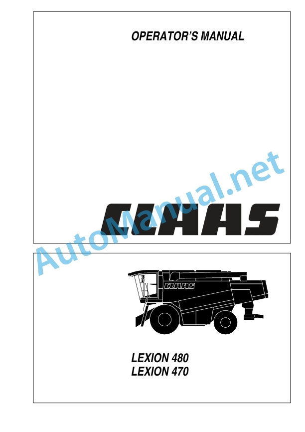
Claas Lexion 480 (546) Combines Operator Manual EN
$50.00
- Model: Lexion 480 (546) Combines
- Type Of Manual: Operator Manual
- Language: EN
- Format: PDF(s)
- Size: 312 MB
File List:
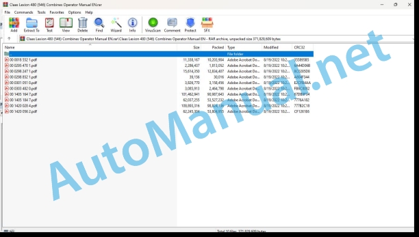
00 0018 552 1.pdf
00 0295 470 1.pdf
00 0298 247 1.pdf
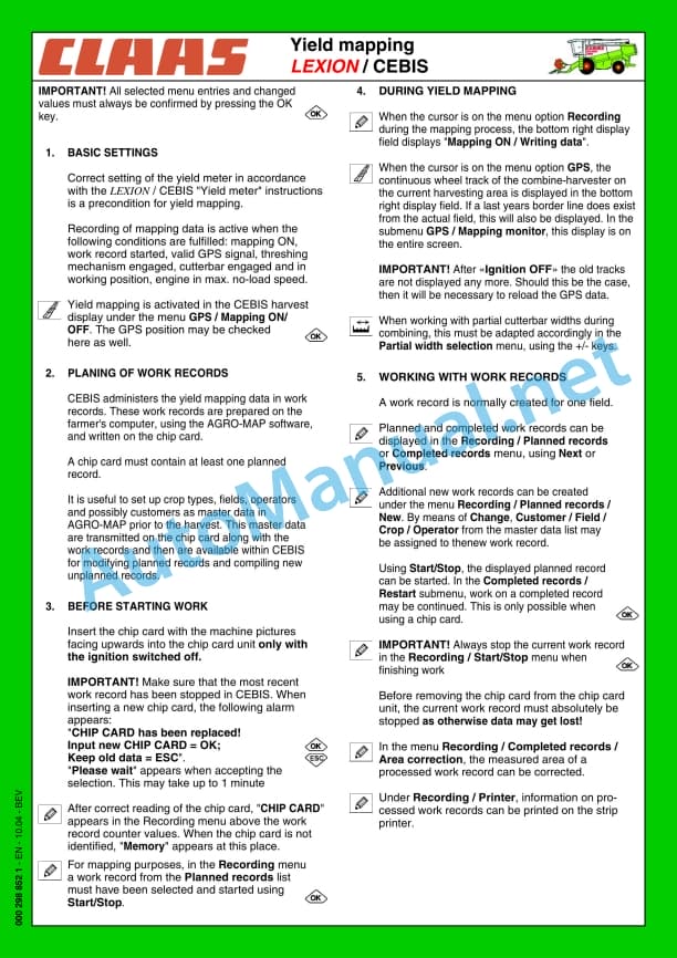
00 0298 852 1.pdf
00 0301 051 0.pdf
00 0303 482 0.pdf
00 1405 164 7.pdf
00 1405 184 7.pdf
00 1420 028 4.pdf
00 1420 056 2.pdf
00 0018 552 1.pdf:
TELEMATICS Website
Table of contents
1 About this Concise Operator’s Manual
1.1 Notes on the manual
1.1.1 Validity of manual
1.1.2 Notes regarding the Concise Operator’s Manual
1.1.3 Notes on warranty
2.1 Intended use
2.1.1 Proper use
3 Product description
3.1 Overview and method of operation
3.1.1 TELEMATICS product variants
3.1.2 TONI (TELEMATICS on implements)
3.1.3 Fleet View
3.1.4 TELEMATICS basic
3.1.5 TELEMATICS advanced
3.1.6 TELEMATICS professional
3.1.7 TELEMATICS app
4 Operating and control elements
4.1 TELEMATICS overview
4.1.1 Illustration conventions of buttons and navigation elements
4.1.2 Symbols and colours
4.2 Menu structure
4.2.1 Start screen
4.2.2 TELEMATICS website site map
4.2.3 Main menu overview
4.2.4
4.2.5
4.2.6
00 0295 470 1.pdf:
1 An-/Abkuppeln Anhänger
1.1 Hinweise zum An-/Abkuppeln von Anhängern
1.1.1 Allgemeine Hinweise
1.1.2 Allgemeine Sicherheitshinweise
1.1.3 Anhänger ankuppeln
1.1.4 Anhänger abkuppeln
1 Hitching/unhitching a trailer
1.1 Information about hitching/unhitching trailers
1.1.1 General information
1.1.2 General safety instructions
1.1.3 Hitching the trailer
1.1.4 Unhitching the trailer
1 Atteler / deteler a trailer
1.1 Conseils pour atteler / deteler the trailers
1.1.1 General councils
1.1.2 General safety advice
1.1.3 Workshop the trailer
1.1.4 Deteler the trailer
1 Hooking / unhooking the trailer
1.1 Instructions for hooking and unhooking the trailer
1.1.1 General warning
1.1.2 General safety rule
1.1.3 Hooking up the trailer
1.1.4 Sgancio del rimorchiHook/unhook the trailer
1.1 Indications relating to hooking/unhooking trailers
1.1.1 General indications
1.1.2 General security measures
1.1.3 Hitch the trailer
1.1.4 Unhook the trailer
1 Coupling / uncoupling trailer
1.1 Indications relating to the coupling / uncoupling of trailers
1.1.1 General indications
1.1.2 General safety instructions
1.1.3 Attach trailer
1.1.4 Uncoupling or towing
1 Aan-/afkoppelen van tänders
1.1 Aanwijzingen bij het aan-/afkoppelen van tänders
1.1.1 General instructions
1.1.2 General safety instructions
1.1.3 Aanhanger aankoppelen
1.1.4 Aanhanger afkoppelen
1 Til-/frakoppling af anhænger
1.1 Anvisings til til-/frakoppling af anhængere
1.1.1 General notices
1.1.2 General safety instructions
1.1.3 Tilkoppling af anhänger
1.1.4 Frakoppling af anhänger
1 Till-/frånkällung av släpvagn
1.1 Anvisningar för till-/frånkolloppung av släpvagnar
1.1.1 General instructions
1.1.2 General safety precautio Tillkoppling av släpvagn
1.1.4 Disconnecting the trailer
1 Til-/frakoppling av tilhenger
1.1 Information on til-/frakoppling av tilhengere
1.1.1 General notices
1.1.2 General security information
1.1.3 Koble på tilhenger
1.1.4 Koble fra tilhengeren
1 Perävaunun täkkäminen/irrotatänä
1.1 Perävaunun küppä-/irrotusohjeet
1.1.1 Generality
1.1.3 Vehicle coupling
1.1.4 Perävaunun irrotus
1 Piekabes piekabinâ²ana/atkabinâ²ana
1.1 Norâdîjumi par piekabju piekabinâ²anu/atkabinâ²anu
1.1.1 Vispârîgie norâdîjumi
1.1.2 Vispârîgie dro²îbas norâdîjumi
1.1.3 Piekabes piekabinâ²ana
1.1.4 Piekabes atkabinâ²ana
1 Priekabø prikabinimas ir atkabinimas
1.1 Nurodymai priekaboms prikabinti ir atkabinti
1.1.1 Instructions
1.1.3 Priekabos prikabinimas
1.1.4 Connecting Priekabos
1.1.1 Üldised juhised
1.1.2 Üldised saifsjuhised
1.1.4 Haagise lahtiühendamine
1 Do-/od¸¶czanie przycepy
1.1 Wżczówki dotycz¶ce do-/odions
1.1.2 General safety tips
1.1.3 Do¸¶czanie przycepy
1.1.4 Od¸¶czanie przycepy
1 Çàêà÷âàíå/îòêà÷âàíå íà ²åìà²êå
1.1 ÓêàçàíèØ çà çàêà÷âàíå/îòêà÷âàíå íà ²åìà²êåòà
1.1.1 Îáùè óêàçàíèØ
1.1.2 Îáùè èíñò²óêöèè çà áåçîïàñíîñò
1.1.3 Çåêà÷âàíå íà ²åìà²êå
1.1.4 Îòêà÷âàíå íà ²åìà²êåòî
1 Pøipojit/odpojit pøívìs
1.1 Pokyny pro pøipojování a odpojování pøívìsù
1.1.1 Vðobecná upozornìní
1.1.2 Vðobeconné bezpeènostní obsední
1.1.3 Personal connection
1.1.4 Personal disconnection
1 Cuplarea and decuplarea remorcii
1.1 Instruc iuni pentru cuplarea și decuplarea remorcilor
1.1.1 Indicate ii general
1.1.2 General safety instruction at work
1.1.3 Couplarea remorcii
1.1.4 Decuplaria remorcii
1 ÓÆíäåóç/Á²ïóÆíäåóç ñõìïõëêïÆìåíïõ
1.1 Õ²ïäåßîåéò ãéá ôç sik fel- / leszállához
1.1.1 General instructions
1.1.2 General safety instructions
1.1.3 A pótkocsi (pótkocsi) felszóksi
1.1.4 A pótkocsi (pótkocsi) leszpóksi
1 Spajanje/odvajanje påres
1.1 Napomene uz spoženje/odvajanje prálakas
1.1.1 Opæenite napomene
1.1.2 Opæenite security napomene
1.1.3 Trailer coupling
1.1.4 Trailer removal
1 Pripojit’/odpojit’ ships
1.1 Pokyny na pripájanie a odpájanie návesov
1.1.1 I saw instructions
1.1.2 Vðobeconné bezpeènostné instructions
1.1.3 Návesu: Pripojenie
1.1.4 Odpojenie návesu
1 Priklop/odklop trailers
1.1 Instructions for priklop/odklop prikolic
1.1.1 Sploðna navoda
1.1.2 Exploding safety warning
1.1.3 Priklop trailers
1.1.4 Priklop trailers
1 Zakaèivanje/otkaèivanje tähälä
1.1 Instructions for the trailer
1.1.1 Opðte napomene
1.1.2 Choose safety instructions
1.1.3 Zakaèiti prikolicu
1.1.4 Otkaèiti prikolicu
1 Ïîäñîåäèíåíèå/îòñîåäèí???? ???????
1.1.1 ????? ????????
1.1.2 ????? ???????? ?? ????????????
1.1.3 ϲ??????????? ??????
1.1.4 ??????????? ?????
1 R?mork ba?lama/??zme
1.1 R?mork ba?lama/??zme ile ilgidi bilgiler
1.1.1 General information
1.1.2 General security uyar?lar?
1.1.3 R?mork ba?lama
1.1.4 R?morkun d?zmelmesi
00 0298 247 1.pdf:
Introduction
Introduction
General information
Road traffic regulations
Identification plate / Serial number
Identification plate
Combine serial number
Engine serial number CATERPILLAR C12
Engine serial number CATERPILLAR C9
Straw chopper identification plate
Cabin serial number
Safety rules
Safety rules
Safety lock
Fire extinguisher
Battery master switch
Wheel chocks
Positioning the wheel chocks
Safety decals with pictorials
Specifications
Conversion factors
CLAAS LEXION 480
CLAAS LEXION 480
CLAAS LEXION 480
CLAAS LEXION 470
CLAAS LEXION 470
CLAAS LEXION 470
Safety features
Front attachments – weights_x0011_and_x0011_dimensions
Prior to operation
Perform the following steps prior to operation
Cabin with Climatic
Operating and display elements
Putting the Climatic into operation
Setting the cabin temperature
Manually setting the evaporator blower speed
Fully automatic heating
Manually setting the heating
Floor heating
REHEAT operation (Dehumidify cab windows)
Displaying the outside temperature
Switching the temperature display to Fahrenheit
Display of malfunction: error in thermometer F0 (cabin, blue)
Display of malfunction: error in thermometer F1 (exhaust, yellow)
Display of malfunction: error in thermometer F2 (outside, red)
Cabin with air conditioner (Standard version)
Cabin with compressor-type air conditioning system
Cabin with heating
Floor heating
Demister System (Fogged windows)
Problem, cause and / or remedy – Compressor-_x0004_type air conditioner
ing and closing the cabin roof
Windscreen washer system
Operator’s platform
Operator’s platform – Overview
Switch console
Monitor (Vehicle information display)
Monitor (Harvest display)
Rotary switch D
Steering column
Ignition switch (S)
Multi-function switch
Vehicle information unit
Multi-function handle
Adjusting the steering column
Swinging the steering column at the top
Steering wheel height adjustment
Central electrics
Swing grain tank unloading tube out and in
Safety feature
Switching grain tank unloading on and off
Switching threshing mechanism on and off
Operator’s seat
Operator’s seat, mechanical
Operator’s seat with air suspension (Optional equipment)
Front ladder
Hinged ladder
Access and ladder extension
Side position lights in case of excess width
Side lights in case of excess width
Rear ladder
Other uses of the rear ladder
Driving the combine
ne speed rotary switch
Manoeuvring
Starting the engine
Gear ranges
Servo gearshift (Optional equipment)
Adjusting the binds of the ground speed control_x0011_lever
Driving behaviour
Foot brake
Parking brake
Stopping the engine
CLAAS Autopilot (Maize picker head)
CLAAS Autopilot (Grain cutterbar)
Adjusting the directional stability of the combine
Setting the laser sensor in the field
Putting the CLAAS Autopilot into operation
Use in rape with left-hand side cutter
Cutterbar hydraulic cylinders
Attaching cutterbar hydraulic cylinders
Third cutterbar cylinder
Rear wheel drive axle
Adjusting rear wheel drive axle from transport to working position
Wheel tread adjustment – Rear wheel drive axle
Adjustable rear axle LEXION 470
Rear axle wheels – steering angle limiter (Adjustable rear axle)
8 t rear axle LEXION 480
Side panels
Opening and closing the side panels and_x0011_the rear door
Adjusting side panel / rear door locks
Cabin and lighting
Headlights, worklights and mirrors
Towing / Crop inspection / Grain tank
Crop inspection
Grain tank
Closing the grain tank openings
Installing dual wheels LEXION 480
Operating the front ladder with dual tyres installed
Additional weights LEXION 470
Installing the rear axle weights
Installing and removing the cutterbar
Installing the cutterbar
Tilting the cutterbar from transport position
Machines equipped with CLAAS Auto Contour
Adjusting the hydraulic cylinder for transverse cutter_x0004_bar control
Machines without CLAAS Auto Contour
Locking cutterbars and maize pickers (Cutterbars without Auto Contour)
Connecting the universal drive shaft
Connecting the reel drive hydraulic hoses (Cutterbar with hydraulic reel drive)
Mounting the stands
Removing the cutterbar
Disconnecting the reel drive hydraulic hoses (Cutterbar with hydraulic reel drive)
Removing the universal drive shaft
Removing the universal coupling
Opening the cutterbar locking
Laying down the cutterbar on the ground
Placing the cutterbar on the cutterbar trailer
Operation CEBIS
Operation – basic machine
Feeder housing
Cutterbar reverse drive
Cutterbar floatation springs
Checking the setting of the cutterbar floatation springs
Cutting height indicator
Cutterbar spring pressure indicator
Blocking the cutterbar springs
Adjusting drop rate of the front attachment
Cutterbar clutch
Engaging and disengaging the cutterbar
Threshing mechanism
Stone trap
Engaging and disengaging the threshing mechanism
Threshing drum
Cleaning the threshing parts
Basic concave setting
Learning the limit stops
Threshing drum speed
Threshing drum drives
Threshing drum two-step variable speed drive
Installing and removing preconcave segments
Concave segment
Removing the concave segment
Installing the concave segment
Unslugging the threing drum
Separation rotors LEXION 480
Separation rotors
Step drive
Variable-speed rotor drive (Optional equipment)
Removing the separation grates
Installing the separation grates
Warning signal
Covering the rotor separating jackets
Separation rotors LEXION 470
Separation rotors
Step drive
Variable-speed rotor drive (Optional equipment)
Dummy concaves
Installing and removing dummy concaves
Installing the dummy concaves
Warning signal
Preparation floor
Frogmouth sieves
Electrical sieve adjustment
Removing the sieves (Electric sieve adjustment system)
Installing the sieves
Tightening torques of axial mountings for_x0011_the_x0011_upper and lower sieves
Sieves – Basic setting
Harvesting without finishing sieves
Cleaning fan
Electric fan speed adjustment
Wind-controlled cleaning step
Adjustment of primary wind duct
Wind board
Fan shutters for combining grass seed and other special cro (Extra equipment)
Dynamic sidehill levelling (3-D cleaning system)
Combine performance monitor
Rotary separation system
Grain delivery
Augers and auger troughs
Grain tank
Grain tank extension
Unloading the grain tank
Grain tank unloading aid (Extra equipment)
Grain tank unloading tube
Swinging the unloading tube out and in
Inspection doors on the grain tank unloading tube
Shear bolt for grain tank unloading
Grain tank unloading – engaging and disengaging
Grain tank access
Automatic chain lubrication – grain tank unloading (Extra equipment)
Straw chopper / Uni-Spreader LEXION 480
Straw chopper
Before using the straw chopper for the first time, check
Adjusting length of cut
Adjusting the cross blade
Putting the straw chopper into operation
Uni-spreader fans
Adjusting the spreading width
Setting of the range of spreader spout swing
Putting the chopper out of operation and conveg_x0004_ the machine for laying swaths
Removing the chopper feed pan
Reducing the chopper speed
Straw chopper / Chaff spreader LEXION 470
Straw chopper
Before using the straw chopper, check
Adjusting spreading width
Spreader hopper height adjustment
Electric deflector adjustment
Adjusting the length of cut
Adjusting cross knife
Putting the straw chopper into operation
Putting the straw chopper out of operation
Chopper position for cutterbar trailer hitching
Reducing the chopper speed
Chaff spreader
Folding the chaff spreader open
Straw spreader
Adjusting the spread pattern
Sieve chart and suggested combine adjustments
Sieve chart
Suggested combine adjustments
Disawner plates
Threshing segment
Problem, cause and / or remedy – Basic machine
Maintenance – basic machine
Important maintenance instructions
Important maintenance instructions and_x0011_safety_x0011_rules
Maintenance schedules lubricants charts
Maintenance schedules
Lubricants_x0011_charts
Hydraulic system
Hydraulic accumulators
Checking the oil level
Changing hydraulic oil
Changing the hydraulic oil filter
Cleaning the coarse filters
Refilling the system after a hydraulic oil change (Sauer 90 R 130 / 90 M 100)
Bleeding the hydraulic cylinders for cutterbar transverse control
Transmission / Brakes
Transmission gearbox
Checking the oil level
Oil change
Final drives (2-step) (20 t / 19 t / 20 t HD)
Checking the oil level
Oil change
Final drives (Planetary gear)
Checking the oil level
Oil change
Threshing drum two-step variable speed drive
Oil change
Checking the oil level
Transfer gearbox (Engine)
Checking the oil level
Oil change
Rotor drive gearboxes
Checking the oil level
Oil change
Grain tank unloading transmission
Checking the oil level
Oil change
Uni-spreader gearbox (straw chopper)
Checking the oil level
Changing the oil
Gear shift control adjustment
Foot brake and brake fluid
Parking brake
Feeder housing
Tension feeder chains
Cleaning the suction blower (extra equipment)
Elevator chains
Tensioning the grain elevator chain (Combines without yield meter)
Tensioning the grain elevator chain (Combines with yield meter)
Tensioning the returns elevator chain
Drive belts / drive chains – basic_x0011_machine
General notes
Drive system diagram, left-hand side
Drive belts and chains
Drive system diagram, right-hand side
Drive belts
Removing the cutterbar drive belt (1) (Cutterbar drive without variable-speed drive)
Installing and tensioning the cutterbar drive belt_x0011_(1)
Removing the cutterbar drive belt (2) (Cutterbar drive with variable-speed drive)
Installing and tensioning the cutterbar drive belt_x0011_(2)
Removing the cutterbar variable-speed drive belt (3)
Installing thcutterbar variable-speed drive belt_x0011_(3)
Removing the impeller drive belt (4)
Installing and tensioning the impeller drive belt_x0011_(4)
Removing the cutterbar intermediate drive belt_x0011_(5)
Installing and tensioning the cutterbar inter_x0004_mediate_x0011_drive belt (5)
Removing the hydraulic pump drive belt (6) for straw spreader / chaff spreader
Installing and tensioning the hydraulic pump drive belt (6) for straw spreader / chaff spreader
Removing the main intermediate drive belt (7)
Installing and tensioning the main intermediate drive belt (7)
Removing the intermediate drive belt for grain tank unloading (8)
Installing and tensioning the intermediate drive belt for grain tank unloading (8)
Removing the straw chopper intermediate drive belt (9)
Installing and tensioning the straw chopper intermediate drive belt (9)
Removing the straw chopper drive belt (10_x0011_and_x0011_11)
Installing and tensioning the straw chopper drive belt (10 and 11)
Adjusting the uni-spreader intermediate drive LEXION 480
Removing the uni-spreader drive belt (12)
Installing and tensioning the uni-spreader drive belt (12)
Adjusting the uni-spreader drive
Installing and tensioning the uni-spreader drive belt (16)
Removing the sieve pan intermediate drive belt (13)
Installing and tensioning the sieve pan inter_x0004_mediate drive belt (13)
Removing the sieve pan intermediate drive belt (14)
Installing and tensioning the sieve pan inter_x0004_mediate drive belt (14)
Removing the sieve pan drive belt (15)
Installing and tensioning the sieve pan drive belt (15)
Adjusting the axial rotor step drive (18)
Adjusting the axial rotor intermediate drive
Removing and installing drive belt (19)
Removing the fan intermediate drive belt (20)
Installing and tensioning the fan intermediate drive belt (20)
Removing the fan drive belt (21)
Installing the fan drive belt (21)
Removing the threshing mechanism variable speed drive belt (22)
Installing the threshing mechanism variable speed drive belt (22)
Removing the threshing drum drive belt_x0011_(23)
Installing and tensioning the threshing drum_x0011_drive_x0011_belt_x0011_(23)
Removing the accelerator drive belt (24)
Installing and tensioning the accelerator drive_x0011_belt (24)
Removing the rotary radiator screen suction drive belt (28)
Installing and tensioning the rotary radiator screen suction drive belt (28)
Tensioning the rotary radiator screen drive_x0011_belt (32)
Tensioning the suction blower drive belt (34)
Removing the grain tank unloading drive chain (17)
Installing and tensioning the grain tank unloading_x0011_drive chain (17)
Cabin / Compressor-type air condi_x0004_tioner_x0011_
Cleaning the filters
Cleaning the units located in the cabin roof
Compressor-type air conditioning system
Cleaning the condenser
Checking the refrigerant level
Replacing the filter receiver-drier
Required refrigerant charge – refrigerant R 134 a
Compressor oil
Maintenance work before the harvest
Combine performance monitor / Fire_x0011_extinguisher_x0011_
Combine performance monitor
Fire extinguisher
Compressed air system (Extra equipment)
Compressed air connections
Draining the compressed air accumulator
Pressure controller
Straw chopper
Removing the knives
Removing the straw guide plate (LEXION 470)
Installing the straw guide plate (LEXION 470)
Removing the straw guide plate (LEXION 480)
Installing the straw guide plate (LEXION 480)
Changing the knives
Replacing the stationary knives
Spreading unit
Installing and adjusting the toothed belt
Speed monitoring
Setting the magnetic pick-ups (sensors)
Winter storage instructions for combines
Maintenance – engine
Important maintenance instructions
Important maintenance instructions and safety_x0011_rules_x0011_
Maintenance schedules and lubricants cha Maintenance schedule
Lubricants chart
Maintenance – engine
Engine overview
Fuel system
Additional fuel tank (Extra equipment)
Replaceable filter of additional fuel tank
Water separator / fuel pre-filter (Extra equipment – small version)
Fuel pre-filter, disassembled:
Water separator / Fuel pre-filter (Extra equipment, replaces fuel pre-filter Fig._x0011_11)
Water separator / fuel pre-filter disassembled:
Fuel filter
Replacing the filter cartridge
Bleeding the fuel system
Checking engine oil level
Engine oil change
Draining the old oil
Oil filter
Filling in engine oil
Cooling system
Water drain plugs on the engine block
Water cooler
Filling the cooling system with coolant
Overpressure
Antifreeze / corrosion protection
Warning notice
Cooling water temperature
Stopping the engine when overheated
Radiator rotary screen
Cleaning the radiator
Dry-type air ner
Warning device
Cleaning the air cleaner intake screen
Cleaning dry-type air cleaner
Cleaning the air cleaner
Safety filter cartridge
Electrical equipment
Alternator
Engine problems, cause and / or remedy
Engine winter storage
Engine preservation
Lubrication chart
Lubricants and lubrication instructions
00 0301 051 0.pdf:
PROFI CAM 3
Table of contents
1 Introduction
1.1 Notes on the manual
1.1.1 Validity of manual
1.1.2 Information about this Operator’s Manual
1.1.3 Symbols and notes
1.1.4 Optional equipment
1.1.5 Qualified specialist workshop
1.1.6 Maintenance information
1.1.7 Warranty notes
1.1.8 Spare parts and technical questions
1.2 Intended use
1.2.1 Intended use
1.2.2 Reasonably foreseeable misuse
2.1 Identifying warnings
2.1.1 Hazard signs
2.1.2 Signal word
2.2 Safety rules
2.2.1 Meaning of Operator’s Manual
2.2.2 Observing safety decals and warnings
2.2.3 Optional equipment and spare parts
3 Product description
3.1 Overview and method of operation
3.1.1 How the PROFI CAM works
3.2 Identification plates and identification number
3.2.1 Position of identification plates
3.2.2 Explanation of PROFI CAM identification plate
3.3 Information on the product
3.3.1 CE marking
4 Operating and control elements
4.1 Camera system
4.1.1 Camera system monitor
4.2 Menu structure
4.2.1 Main menu
4.2.2
4.2.3
4.2.4
4.2.5
4.2.6
5 Technical specifications
5.1 PROFI CAM
5.1.1 Monitor
5.1.2 Camera
5.1.3 Switch box
5.1.4 Degree of protection against foreign bodies and water
6 Preparing the product
6.1 Shutting down and securing the machine
6.1.1 Switching off and securing the machine
6.2 Prior to operation
6.2.1 Carry out prior to operation
6.2.2 Installing the sun protection
6.2.3 Aligning the camera
6.2.4 Connecting the camera electrics
7 Operation
7.1 Monitor
7.1.1 Switching on the monitor
7.1.2 Calling up the menu
7.1.3 Setting a menu item
7.1.4 Setting the image orientation
7.1.5 Setting automatic screen darkening
7.1.6 Image mirroring
7.1.7 Setting the trigger view
7.1.8 Setting the follow-up time for trigger view
7.1.9 Setting the display mode
7.1.10 Activating/deactivating a display mode
8 Faults and remedies
8.1 Electrical and electronic system
8.1.1 Overview of problems on PROFI CAM camera system
8.1.2 Replacing the switch box fuse
9 Maintenance
9.1 Maintenance intervals
9.1.1 Every 10 operating hours or daily
9.2 Camera system
9.2.1 Checking the camera system for dirt
9.2.2 Cleaning the camera
9.2.3 Cleaning the switch box
9.2.4 Cleaning the monitor
10 Placing out of operation and disposal
10.1 General Information
10.1.1 Putting out of operation and disposal
11 Technical terms and abbreviations
11.1 Abbreviations
11.1.1 Units
11.1.2 Abbreviations
11.1.3 Technical terms
00 0303 482 0.pdf:
PROFI CAM 4
Table of contents
1 Introduction
1.1 Notes on the manual
1.1.1 Validity of manual
1.1.2 Information about this Operator’s Manual
1.1.3 Symbols and notes
1.1.4 Optional equipment
1.1.5 Qualified specialist workshop
1.1.6 Maintenance information
1.1.7 Notes on warranty
1.1.8 Spare parts and technical questions
1.2 Intended use
1.2.1 Intended use
1.2.2 Reasonably foreseeable misuse
2.1 Identifying warnings
2.1.1 Hazard signs
2.1.2 Signal word
2.2 Safety rules
2.2.1 Meaning of Operator’s Manual
2.2.2 Structural changes
2.2.3 Optional equipment and spare parts
2.2.4 Operation only following proper putting into operation
2.2.5 Technical status
2.2.6 Respecting technical limit values
Respecting technical limit values
2.2.7 Hazards when driving on roads and fields
3 Product description
3.1 Overview and method of operation
3.1.1 How the PROFI CAM works
3.2 Identification plates and identification number
3.2.1 Identification plates
3.3 Information on the product
3.3.1 CE marking
4 Operating and display elements
4.1 Camera system
4.1.1 Camera system monitor
4.1.2 CEBIS
4.2 Menu structure
4.2.1 Main menu
4.2.2
4.2.3
4.2.4
4.2.5
4.2.6
5 Technical specifications
5.1 PROFI CAM
5.1.1 Monitor
5.1.2 Camera
5.1.3 Switch box
6 Preparing the product
6.1 Switching off and securing the machine
6.1.1 Switching off and securing the machine
6.2 Prior to putting into operation
6.2.1 Carry out prior to operation
6.2.2 Installing the sun protection
6.2.3 Aligning the camera
7 Operation
7.1 Monitor
7.1.1 Switching on the monitor
7.1.2 Calling up the menu
7.1.3 Setting a menu item
7.1.4 Setting the image orientation
7.1.5 Setting automatic screen darkening
7.1.6 Image mirroring
7.1.7 Setting the trigger view
7.1.8 Setting the follow-up time for trigger view
7.1.9 Setting the display mode
7.1.10 Activating/deactivating a display mode
8 Faults and remedies
8.1 Electric and electronic system
8.1.1 Overview of problems on PROFI CAM camera system
9 Maintenance
9.1 Maintenance intervals
9.1.1 Every 10 operating hours or daily
9.2 Camera system
9.2.1 Checking the camera system for dirt
9.2.2 Cleaning the camera
9.2.3 Cleaning the switch box
9.2.4 Cleaning the monitor
10 Putting out of operation and disposal
10.1 General information
10.1.1 Putting out of operation and disposal
11 Technical terms and abbreviations
11.1 Abbreviations
11.1.1 Units
11.1.2 Abbreviations
11.1.3 Technical terms
00 1405 164 7.pdf:
Table of contents
1 Introduction
1.1 General information
1.1.1 Validity of Manual
1.1.2 Information about this Operator’s Manual
1.1.3 Symbols and notes
1.1.4 Optional equipment
1.1.5 Qualified specialist workshop
1.1.6 Maintenance notes
1.1.7 Notes on warranty
1.1.8 Spare parts and technical questions
1.1.9 Licensing for road traffic
Sample report
Clearance certificate
General operating permit
1.2 Intended use
1.2.1 Intended use
1.2.2 Reasonably foreseeable misuse
2.1 Identifying warnings
2.1.1 Hazard signs
2.1.2 Signal word
2.2 Safety rules
2.2.1 Meaning of Operator’s Manual
2.2.2 Update of terminal software
2.2.3 Requirements made on all persons working with the product
2.2.4 Hazard areas
Hazard areas
2.2.5 Interaction between the control terminal and the machine or tractor
2.2.6 Structural changes
2.2.7 Optional equipment and spare parts
2.2.8 Use of USB devices
2.2.9 Operation only following proper putting into operation
2.2.10 Technical status
2.2.11 Hazard from damage on the product
2.2.12 Respecting technical limit values
Respecting technical limit values
2.2.13 Preparing the product for road travel
2.2.14 Hazards when driving on the road with an ISOBUS implement
Switching on the terminal during road travel.
2.2.15 Hazards when driving on the road and on the field
2.2.16 Electrocution by electrical system
2.2.17 Potentially fatal electric shock from overhead lines
2.2.18 Liquids under pressure
2.2.19 Maintenance operations and repair work
2.2.20 Driving with the GPS PILOT
Road travel
2.2.21 Working with Task Control* and Section Control*
3 Product description
3.1 Overview and method of operation
3.1.1 Overview of GPS PILOT – Hydraulic system
3.1.2 Overview of GPS PILOT – Steer ready
3.1.3 Overview of GPS PILOT FLEX
3.1.4 Overview of GPS PILOT ex works
3.1.5 Overview of the S10 terminal
3.1.6 Overview of navigation computer (ECU)
3.1.7 Electric steering wheel
3.1.8 Overview of correction signals
EGNOS/WAAS/MSAS
Omnistar HP / XP
John Deere Repair Technical Manual PDF
John Deere Transmission Control Unit Component Technical Manual CTM157 15JUL05
John Deere Repair Technical Manual PDF
John Deere Parts Catalog PDF
John Deere Tractors 6300, 6500, and 6600 Parts Catalog CQ26564 (29SET05) Portuguese
John Deere Repair Technical Manual PDF
John Deere Repair Technical Manual PDF
John Deere Repair Technical Manual PDF
John Deere Application List Component Technical Manual CTM106819 24AUG20
John Deere Repair Technical Manual PDF
John Deere DF Series 150 and 250 Transmissions (ANALOG) Component Technical Manual CTM147 05JUN98
John Deere Repair Technical Manual PDF
John Deere Diesel Engines POWERTECH 2.9 L Component Technical Manual CTM126 Spanish
John Deere Repair Technical Manual PDF
John Deere Repair Technical Manual PDF

