Claas Lexion 530-510 (583) Combines Operator Manual EN
$50.00
- Model: Lexion 530-510 (583) Combines
- Type Of Manual: Operator Manual
- Language: EN
- Format: PDF(s)
- Size: 366 MB
File List:
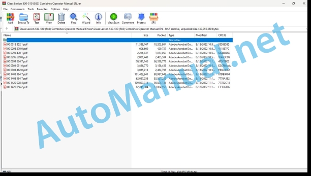
00 0018 552 1.pdf
00 0295 270 0.pdf
00 0295 470 1.pdf
00 0295 699 0.pdf
00 0299 524 7.pdf
00 0301 051 0.pdf
00 0303 482 0.pdf
00 1405 164 7.pdf
00 1405 184 7.pdf
00 1420 028 4.pdf
00 1420 056 2.pdf
00 0018 552 1.pdf:
TELEMATICS Website
Table of contents
1 About this Concise Operator’s Manual
1.1 Notes on the manual
1.1.1 Validity of manual
1.1.2 Notes regarding the Concise Operator’s Manual
1.1.3 Notes on warranty
2.1 Intended use
2.1.1 Proper use
3 Product description
3.1 Overview and method of operation
3.1.1 TELEMATICS product variants
3.1.2 TONI (TELEMATICS on implements)
3.1.3 Fleet View
3.1.4 TELEMATICS basic
3.1.5 TELEMATICS advanced
3.1.6 TELEMATICS professional
3.1.7 TELEMATICS app
4 Operating and control elements
4.1 TELEMATICS overview
4.1.1 Illustration conventions of buttons and navigation elements
4.1.2 Symbols and colours
4.2 Menu structure
4.2.1 Start screen
4.2.2 TELEMATICS website site map
4.2.3 Main menu overview
4.2.4
4.2.5
4.2.6
00 0295 270 0.pdf:
1 Einleitung
1.1 Allgemeine Hinweise
1.1.1 Handling of the Anleitung
1.1.2 Gültigkeit der Anleitung
2 Vor Inbetriebnahme
2.1 Mähdrescher fahren mit mechanischer / elektro-hydraulischer Fahrbetätigung
2.1.1 Schaltvorgang EHS-Notbetrieb über Gang-Taster (ab Maschinen-Nr. …)
3 Wartung – Grundmaschine
3.1 Schmierstofftabellen
3.1.1 Schmierstoffe
4 Wartung Engine
4.1 Wartungstabellen
4.1.1 Wartungstabelle CATERPILLAR Engine
1 Introduction
1.1 General Information
1.1.1 How to use this manual
1.1.2 Validity of instructions
2 Prior to operation
2.1 Driving the combine with mechanical / electro-hydraulic ground drive control
2.1.1 EHS emergency operation shifting procedure using the gear touch sensor (from serial no. …)
3 Maintenance – Basic machine
3.1 Lubric charts
3.1.1 Lubricants
4 Engine maintenance
4.1 Maintenance schedules
4.1.1 CATERPILLAR engine maintenance schedule
1 Introduction
1.1 General advice
1.1.1 Use of the notice
1.1.2 Validity of the notice
2 Avant la mise en service
2.1 Conduite de la moissonneuse-batteuse avec commande mécanique/électrohydraulique d’avancement
2.1.1 Processus de passage des vitesses en servicing de secaurs EHS au moyen de la touche rapport (à de la machine N˚ …)
3 Entretien – basic machine
3.1 Tableaux des lubricants
3.1.1 Lubricants
4 Engine maintenance
4.1 Tableaux d’entertien
4.1.1 CATERPILLAR engine maintenance table
1 Introduction
1.1 General indications
1.1.1 Application of the user manual
1.1.2 Validity of the user manual
2 Prima della messa in exercise
2.1 Advancement of the mietitrebbia with mechanical command / hydraulic electric
2.1.1 In this button you can start the EHS emergency using a button (from the machine No. …)
3 Maintenance – base machine
3ricating tab
3.1.1 Lubricants
4 Motor maintenance
4.1 Maintenance tab
4.1.1 CATERPILLAR engine maintenance table
1. Introduction
1.1 General instructions
1.1.1 Using the instructions
1.1.2 Validity of instructions
2 Before start-up
2.1 Driving the combine with a mechanical / electro-hydraulic feed drive
2.1.1 EHS gear changing process in emergency operation, using the gear button (from machine no. …)
3 Maintenance – Base machine
3.1 Lubricant tables
3.1.1 Lubricant
4 Engine maintenance
4.1 Maintenance tables
4.1.1 CATERPILLAR engine maintenance table
00 0295 470 1.pdf:
1 An-/Abkuppeln Anhänger
1.1 Hinweise zum An-/Abkuppeln von Anhängern
1.1.1 Allgemeine Hinweise
1.1.2 Allgemeine Sicherheitshinweise
1.1.3 Anhänger ankuppeln
1.1.4 Anhänger abkuppeln
1 Hitching/unhitching a trailer
1.1 Information about hitching/unhitching trailers
1.1.1 General information
1.1.2 General safety instructions
1.1.3 Hitching the ter
1.1.4 Unhitching the trailer
1 Atteler / deteler a trailer
1.1 Conseils pour atteler / deteler the trailers
1.1.1 General councils
1.1.2 General safety advice
1.1.3 Workshop the trailer
1.1.4 Deteler the trailer
1 Hooking / unhooking the trailer
1.1 Instructions for hooking and unhooking the trailer
1.1.1 General warning
1.1.2 General safety rule
1.1.3 Hooking up the trailer
1.1.4 Sgancio del rimorchio
1 Hook/unhook the trailer
1.1 Indications relating to hooking/unhooking trailers
1.1.1 General indications
1.1.2 General security measures
1.1.3 Hitch the trailer
1.1.4 Unhook the trailer
1 Coupling / uncoupling trailer
1.1 Indications relating to the coupling / uncoupling of trailers
1.1.1 General indications
1.1.2 General safety instructions
1.1.3 Attach trailer
1.1.4 Uncoupling or towing
1 Aan-/afkoppelen van tänders
1.1 Aanwijzingen bij het aan-/afkoppelen van tänders
1.1.1 General instructions
1.1.2 General safety inructions
1.1.3 Aanhanger aankoppelen
1.1.4 Aanhanger afkoppelen
1 Til-/frakoppling af anhænger
1.1 Anvisings til til-/frakoppling af anhængere
1.1.1 General notices
1.1.2 General safety instructions
1.1.3 Tilkoppling af anhänger
1.1.4 Frakoppling af anhänger
1 Till-/frånkällung av släpvagn
1.1 Anvisningar för till-/frånkolloppung av släpvagnar
1.1.1 General instructions
1.1.2 General safety precautions
1.1.3 Tillkoppling av släpvagn
1.1.4 Disconnecting the trailer
1 Til-/frakoppling av tilhenger
1.1 Information on til-/frakoppling av tilhengere
1.1.1 General notices
1.1.2 General security information
1.1.3 Koble på tilhenger
1.1.4 Koble fra tilhengeren
1 Perävaunun täkkäminen/irrotatänä
1.1 Perävaunun küppä-/irrotusohjeet
1.1.1 Generality
1.1.3 Vehicle coupling
1.1.4 Perävaunun irrotus
1 Piekabes piekabinâ²ana/atkabinâ²ana
1.1 Norâdîjumi par piekabju piekabinâ²anu/atkabinâ²anu
1.1.1 Vispârîgie no??bas nor?d?jumi
1.1.3 Piekabes piekabin?ana
1.1.4 Piekabes atkabin?ana
1 Priekab? prikabinimas ir atkabinimas
1.1 Nurodymai priekaboms prikabinti ir atkabinti
1.1.1 Instructions
1.1.3 Priekabos prikabinimas
1.1.4 Connecting Priekabos
1.1.1 ?ldised juhised
1.1.2 ?ldised saifsjuhised
1.1.4 Haagise lahti?hendamine
1 Do-/od??czanie przycepy
1.1 W|cz?wki dotycz?ce do-/od??czania przyczep
1.1.1 General instructions
1.1.2 General safety tips
1.1.3 Do??czanie przycepy
1.1.4 Od??czanie przycepy
1 ?????????/????????? ?? ??????
1.1 ???????? ?? ?????????/????????? ?? ????????
1.1.1 ???? ????????
1.1.2 ???? ????????? ?? ???????????
1.1.3 ????????? ?? ??????
1.1.4 ????????? ?? ????????
1 P?ipojit/odpojit p??v?s
1.1 Pokyny pro p?ipojov?n? a odpojov?n? p??v?s?
1.1.1 V?obecn? upozorn?n?
1.1.2 V?obeconn? bezpe?nostn? obsedn?
1.1.3 Personal connection
1.1.4 Personal disconnection
1 Cuplarea and decuplarea remorcii
1.1 Instruc iuni pentru cuplarea și decuplarea remorcilor
1.1.1 Indicate ii general
1.1.2 General safety instruction at work
1.1.3 Couplarea remorcii
1.1.4 Decuplaria remorcii
1 ÓÆíäåóç/Á²ïóÆíäåóç ñõìïõëêïÆìåíïõ
1.1 Õ²ïäåßîåéò ãéá ôç óÆíäåóç/á²ïóÆíäåóç ñõìïõëêïÆìåíùí
1.1.1 ÃåíéêÅò ïäçãßåò
1.1.2 ÃåíéêÅò ïäçãßåò áóöáëåßáò
1.1.3 ÓÆíäåóç êïôóáäüñïõ
1.1.4 Á²ïóÆíäåóç ôïõ ñõìïõëêïÆìåíïõ
1 A pótkocsi fel- / lesköpa
1.1 Utasítás a pótkocsik fel- / leszállához
1.1.1 General instructions
1.1.2 General safety instructions
1.1.3 A pótkocsi (pótkocsi) felszóksi
1.1.4 A pótkocsi (pótkocsi) leszpóksi
1 Spajanje/odvajanje påres
1.1 Napomene uz spoženje/odvajanje prálakas
1.1.1 Opæenite napomene
1.1.2 Opæenite security napomene
1.1.3 Trailer coupling
1.1.4 Trailer removal
1 Pripojit’/odpojit’ ships
1 Priklop/odklop trailers
1.1 Instructions for priklop/odklop prikolic
1.1.1 Sploðna navoda
1.1.2 Exploding safety warning
1.1.3 Priklop trailers
1.1.4 Priklop trailers
1 Zakaèivanje/otkaèivanje tähälä
1.1 Instructions for the trailer
1.1.1 Opðte napomene
1.1.2 Choose safety instructions
1.1.3 Zakaèiti prikolicu
1.1.4 Otkaèiti prikolicu
1 Ïîäñîåäèíåíèå/îòñîåäèíåíèå ï²èöåïà
1.1 ÓêàçàíèØ ïî ïîäñîåäèíåíè /îòñîåäèíåíè ï²èöåïîâ
1.1.1 Îáùèå óêàçàíèØ
1.1.2 Îáùèå óêàçàíèØ ïî áåçîïàñíîñòè
1.1.3 ϲèñîåäèíåíèå ï²èöåïà
1.1.4 Îòñîåäèíèòü ï²èöåï
1 Römork ba²lama/çözme
1.1 Römork ba²lama/çözme ile ilgidi bilgiler
1.1.1 General information
1.1.2 General security uyarÆlarÆ
1.1.3 Römork ba²lama
1.1.4 Römorkun dözmelmesi
00 0295 699 0.pdf:
1 Introduction
1.1 Gdisplays
2.2.1 Keypad
2.2.2 Rotary switch and direct menu
2.2.3 Vehicle control display
2.2.4 Harvest display
2.2.5 Main menu
2.2.6 Prior to initial commissioning
2.2.7 Menu Settings / Front attachment
2.2.8 Menu Settings / Diesel engine
2.2.9 Menu Settings / Speeds
2.2.10 Menu Settings / Secondary separation
2.2.11 Settings menu / Autopilot
2.2.12 Settings menu / CEBIS
2.2.13 Front attachment menu
2.2.14 Reel menu
2.2.15 No. of partial widths menu
2.2.16 Driving menu
2.2.17 Crop setting menu
2.2.18 Yield measuring menu
2.2.19 Recorder menu
2.2.20 Maintenance menu
2.2.21 Reference values for pulses per 100m
3 Prior to operation
3.1 CRUISE PILOT
3.1.1 Learning zero throughput
3.1.2 Preselecting the CRUISE PILOT strategy
3.1.3 Switch on CRUISE PILOT
3.1.4 Switch off CRUISE PILOT
3.1.5 Saving the cruise control ground speed (km/h)
3.1.6 Changing the cruise control ground speed (km/h)
3.1.7 Saving the throughput (t/h) of the crop
3.1.8 Changing the throughput (t/h) of the crop
3.1.9 CRUISE PILOT – driving behaviour when emptying the grain tank
4 Operation – Basic machine
4.1 Cab / Operator’s platform
4.1.1 Cutting height control
4.1.2 Saving the ground pressure
4.1.3 Saving the cutting height
00 0299 524 7.pdf:
1 Introduction
1.1 General Information
1.1.1 How to use this manual
1.1.2 Validity of instructions
2 General Information
2.1 Road traffic
2.2 Important notice
2.3 Identification plate / Serial number
2.3.1 Identification plate / Serial number
2.3.2 Identification plate
2.3.3 Machine serial number
2.3.4 Engine serial number
2.3.5 Straw chopper identification plate
2.3.6 Cab serial number
2.4 Attachment parts / machine body
2.4.1 Access to the workplace and maintenance areas
3 Safety Rules
3.1 Safety rules
3.1.1 General information
3.1.2 Identification of warning and danger signs
3.1.3 Intended use
3.1.4 Reasonable foreseeable misuse
3.1.5 General safety and accident prevention regulations
3.1.6 Transporting passengers, instructor, operating personnel
3.1.7 Driving operations
3.1.8 Leaving the combine harvester
3.1.9 Front attachments (cutterbar etc.) and other components
3.1.10 Air conditioner
3.1.11 Maintenance
3.1.12 Basic rule
3.1.13 Accumulators
3.1.14 Decommissioning and disposal
3.1.15 Cylinder safety lock
3.1.16 Fire extinguisher
3.1.17 Battery isolating switch
3.1.18 Wheel chocks
3.1.19 Jack up the machine
3.1.20 Loading and tying down the machine
3.1.21 Hydraulic system
3.1.22 Danger of injury due to escaping hydraulic liquid
3.2 Safety decals with pictorials
3.2.1 General information on safety decals
3.2.2 Safety decals
4 Specifications
4.1 CLAAS LEXION 560 / 550 / 540 / 540 C
4.1.1 Cab / Operator’s platform
4.1.2 Cutterbar
4.1.3 Threshing mechanism
4.1.4 Separation
4.1.5 Cleaning (Standard cleaning system)
4.1.6 Grain delivery
4.1.7 Engine
4.1.8 Chassis
4.1.9 Tyres and tyre pressures
4.1.10 Torque settings of wheel bolts
4.1.11 Track width
4.1.12 Transport position / Working position
4.1.13 Weights
4.1.14 Safety features
4.2 CLAAS LEXION 530 / 520
4.2.1 Cab / Operator’s platform
4.2.2 Cutterbar
4.2.3 Threshing mechanism
4.2.4 Separation
4.2.5 Cleaning (Standard cleaning system)
4.2.6 Grain delivery
4.2.7 Engine
4.2.8 Chassis
4.2.9 Tyres and tyre pressures
4.2.10 Torque settings of wheel bolts
4.2.11 Track width
4.2.12 Transport position / Working position
4.2.13 Weights
4.2.14 Safety features
4.3 CLAAS LEXION 510
4.3.1 Cab / Operator’s platform
4.3.2 Cutterbar
4.3.3 Threshing mechanism
4.3.4 Separation
4.3.5 Cleaning (Standard cleaning system)
4.3.6 Grain delivery
4.3.7 Engine
4.3.8 Chassis
4.3.9 Tyres and tyre pressures
4.3.10 Torque settings of wheel bolts
4.3.11 Track width
4.3.12 Transport position / Working position
4.3.13 Weights
4.3.14 Safety features
5 Prior to operation
5.1 General Information
5.1.1 Initial operation check list
5.1.2 Loading and tying down the machine
5.2.1 Cab with automatic air conditioner
5.2.2 Automatic air conditioner
5.2.3 Putting the automatic air conditioner into operation
5.2.4 Setting the cab temperature
5.2.5 Manually setting the evaporator blower speed
5.2.6 Activating ECON operating mode
5.2.7 Deactivating ECON operating mode
5.2.8 REHEAT operation (Dehumidify cab windows)
5.2.9 Displaying the outside temperature
5.2.10 Changing the temperature display to _x001E_Fahrenheit
5.2.11 Floor heating
5.2.12 Display of malfunction – Error in thermometer F0 (cab, blue)
5.2.13 Display of malfunction – Error in thermometer F1 (exhaust, yellow)
5.2.14 Display of malfunction – Error in thermometer F2 (outside, red)
5.2.15 Cab with air conditioner (Standard version)
5.2.16 Putting the air conditioning system into operation
5.2.17 Heater
5.2.18 Floor heating
5.2.19 REHEAT operation (Dehumidify cab windows)
5.2.20 Problem, possible cause or remedy – air conditioner system
5.2.21 Cooling box
5.2.22 Cooling unit (option)
5.2.23 Cooling bag (option)
5.2.24 Ice bucket (option)
5.2.25 Windscreen washer
5.2.26 Crop inspection
5.2.27 Opening and closing the cab roof
5.2.28 Cab emergency exit
5.2.29 Operator’s platform overview
5.2.30 Control console
5.2.31 Screen (vehicle information display)
5.2.32 Screen (harvest display)
5.2.33 Keys C / Rotary switch D
5.2.34 Ignition switch
5.2.35 Multifunction switch
5.2.36 Vehicle information unit
5.2.37 Multifunction handle
5.2.38 Reel height limitation
5.2.39 Steering column adjustment
5.2.40 Steering wheel height adjustment
5.2.41 Central terminal compartment
5.2.42 Contents – Central terminal compartment (uto serial no. …)
5.2.43 Fuses (up to serial no. …)
5.2.44 Relays (up to serial no. …)
5.2.45 Contents – Central terminal compartment (from serial no. …)
5.2.46 Fuses (from serial no. …)
5.2.47 Relays (from serial no. …)
5.2.48 Operator’s seat
5.2.49 Operator’s seat, mechanical
5.2.50 Air-suspended driver’s seat
5.3 Lighting and socket outlets
5.3.1 Headlights, working lights, mirrors
5.3.2 Sidefinder (option)
5.3.3 Pathfinder lighting
5.3.4 Side position lights in case of excess width
5.3.5 Socket outlet 12 V
5.3.6 CDS 5000 diagnosis connection socket outlet
5.4 Access ladder
5.4.1 Access and ladder extension
5.4.2 Pre-assembling the front ladder (from serial no. …)
5.4.3 Installing the front ladder
5.4.4 Swivelling the front ladder (up to serial no. …)
5.4.5 Swivelling the front ladder (from serial no. …)
5.4.6 Ladder starting protection
5.4.7 Rear ladder
5.5 Side panels
5.5.1 Opening and closi the side panels and the tailgate
5.5.2 Opening the tailgate
5.5.3 Adjusting the gripping height of the side panels
5.5.4 Adjusting the side panel lock
5.5.5 Tool cabinet
5.6 Mud guards / Side panels / Hitch block / Transport trailer
5.6.1 Installing the mudguards
5.6.2 Adapting the side panels (Rice harvesting machines)
5.6.3 Fitting the hitch block
5.6.4 Converting the transport trailer to suit the machine
5.7 Rear axles (Standard cleaning system)
5.7.1 Rear axle overview
5.7.2 Rear drive axle 000 669 835 6
5.7.3 Rear axle 000 768 705 1
5.7.4 Rear axle 000 770 920 1
5.7.5 Rear axle 000 769 600 4
5.7.6 Rear axle 000 770 347 1
5.7.7 Rear axle 000 770 810 1
5.7.8 Converting the rear drive axle from transport to working position
5.7.9 Rear drive axle – Adjusting the track width
5.7.10 Rear drive axle 000 694 760 1 – Adjusting the steering stop
5.7.11 Converting the rear axle 000 770 920 1 / 000 768 705 1 from transport to working position
5.7.12 Converting the rear axle 000 769 600 4 from transport to working position
5.7.13 Rear axle 000 769 600 4 – Adjusting the track width
5.7.14 Converting the rear axle 000 770 347 1 / 000 770 810 1 from transport to working position
5.7.15 Rear axle 000 770 347 1 – Adjusting the track width
5.8 Additional weights of rear axle
5.8.1 Additional weights on rear axle LEXION 560 – 540 Standard cleaning system
5.8.2 Additional weights on rear axle LEXION 530 – 510 Standard cleaning system
5.8.3 Liquid filling of rear axle tyres
5.8.4 Installing the rear axle weight
5.8.5 Shipping package – rear axle weight (Rear drive axle)
5.8.6 Installing the rear axle weight
5.8.7 Shipping package – rear axle weight (adjustable and rigid rear axle)
5.9 Cutterbar hydraulic cylinders
5.9.1 Fitting the cutterbar hydraulic cylinders with springs
5.9.2 Number of cutterbar cylinders (LEXION 560 – 540)
5.9.3 Number of cutterbar cylinders (LEXION 530 – 510)
5.9.4 Installing the cutterbar floatation springs hydraulic cylinder
5.10 Accumulator
5.10.1 Filling the accumulator for CLAAS AUTO CONTOUR II
5.10.2 Special tool for filling the CLAAS AUTO CONTOUR II accumulator
5.11 Dual fitments
5.11.1 Installing the dual wheels
5.11.2 Use of front ladder when dual fitments are fitted (up to serial no. …)
5.11.3 Use of front ladder when dual fitments are fitted (from serial no. …)
5.12 Grain tank
5.12.1 Closing the grain tank drain holes
5.12.2 Open the grain tank cover completely by hand
5.13 Driving the combine with mechanical control
5.13.1 Driving the combine in general
5.13.2 Ground speed control lever variants
5.13.3 Engine speed rotary switch
5.13.4 Medium engine idle speed
5.13.5 Starting the engine
5.13.6 Forward travel / reverse travel
5.13.7 Gear selection
5.13.8 Setting the ground speed control lever to move easily
5.13.9 Setting the ground speed control lever to move easily
5.13.10 Stopping
5.13.11 Machine driving characteristics
5.13.12 Handling with cutterbar trailer
5.13.13 Steering
5.13.14 Coupling / decoupling brake pedals of the foot brake
5.13.15 Brake lining wear indicator (up to serial no. …)
5.13.16 Parking brake
5.13.17 Stopping the engine
5.13.18 Engaging/disengaging the CLAAS 4-Trac system
5.13.19 Towing the machine
5.13.20 Forward towing
5.13.21 Reverse towing
5.13.22 EHS emergency shifting using the gear pushbutton (from serial no. …)
5.13.23 Emergency operation decal – Electro-hydraulic gearshift (EHS)
5.13.24 Engaging the neutral gearbox position mechanically
5.13.25 Restoring the original state (gearbox can again be shifted electro-hydraulically)
5.13.26 Engaging the neutral gearbox position hydraulically
5.13.27 Engaging the 2nd gear hydraulically
5.14 CLAAS Autopilot (Maize picker)
5.14.1 Putting the CLAAS Autopilot into operation
5.15 CLAAS Autopilot (Grain cutterbar)
5.15.1 Adjusting the directional stability of the combine harvester
5.15.2 Setting the laser sensor in the field
5.15.3 Rough adjustment
5.15.4 Fine adjustment
5.15.5 Laser sensor (crop edge has moved out of visible range)
5.15.6 Adjusting the right laser sensor (accessory)
5.15.7 Putting the CLAAS Autopilot into operation
5.15.8 Use in rape with left side cutter
5.16 Information about hitching/ unhitching trailers
5.16.1 General information
5.16.2 General safety instructions
5.16.3 Hitching the trailer
5.16.4 Unhitching the trailer
6 Installing and removing the cutterbar
6.1 Installing the cutterbar
6.1.1 Tilting the cutterbar from transport position
6.1.2 Adjusting the cutterbar cross levelling hydraulic cylinder (up to serial no. …)
6.1.3 Adjusting the cutterbar cross levelling hydraulic cylinder (from serial no. …)
6.1.4 Aligning the coupling pins
6.1.5 Attaching the front attachment
6.1.6 Locking cutterbars and maize pickers (Cutterbars without Auto Contour)
6.1.7 Connecting the universal drive shaft
6.1.8 Mounting the stands
6.2 Removing the cutterbar
6.2.1 Removing the universal coupling
6.2.2 Removing the universal drive shaft
6.2.3 Opening the cutterbar locking
6.2.4 Laying down the cutterbar on the ground
6.2.5 Placing the cutterbar on the cutterbar trailer
7 CEBIS operation (Version 8.23)
7.1 CLAAS CEBIS on-board information system
7.2 CEBIS monitor and rotary switch
7.2.1 C keys
7.2.2 Rotary switch D
7.2.3 Flagging Box
7.2.4 Multifunction handle
7.2.5 Monitor areas E (Harvest display)
7.3 Rotary switch D
7.4 Prior to initial operation
7.5 Vehicle information display
7.6 Harvest display
7.7 Montana control system
7.7.1 Axle control mode
7.7.2 Cutting angle control
7.7.3 Lateral levelling control
7.7.4 Montana axle end stops
7.7.5 Cutting angle limits
7.7.6 Lateral levelling limits
7.7.7 Display period
7.8 CLAAS CRUISE PILOT
7.8.1 Maximum ground speed
7.8.2 Zero throughput
7.9 Yield mapping
7.10 Flagging
7.11.1 Mapping ON/OFF
7.11.2 Mapping monitor
7.11.3 Load GPS data
7.12 Preset reel values
7.12.1 Horizontal reel position
7.12.2 Reel speed
7.12.3 Reel height
7.13 Preset front attachment values
7.13.1 Snapping plate clearance
7.13.2 Cutterbar table length
7.13.3 CAC settings
7.13.4 CAC setting for LEXION Montana
7.14 Partial width selection
7.15 Yield meter
7.15.1 Components
7.15.2 Basic settings and calibration
7.15.3 Preparations for yield measuring
7.15.4 Moisture measurement ON/OFF, Moisture correction, Storage moisture
7.15.5 A quick way to obtain reasonable measuring data
7.16 Yield measuring
7.16.1 Calibration factor
7.16.2 Yield zero point measuring
7.16.3 Test-weighing
7.16.4 Weight measured
7.16.5 Moisture correction
7.16.6 Moisture measurement ON/OFF
7.16.7 Zero angle
7.16.8 Storage moisture
7.16.9 Display dry yield
7.17 Crop-dependent settings
7.17.1 List of crops
7.17.2 Cleaning by blowing
7.18 Recording
7.18.1 Planned records
7.18.2 Start / Stop
7.18.3 Completed records
7.18.4 Daily recorder
7.18.5 Total recorder
7.18.6 Crop recorder
7.18.7 Copying the chip card
7.19 Adjustments
7.19.1 Cutterbar
7.19.2 Speeds
7.19.3 Tachometer
7.19.4 Separation
7.19.5 CEBIS
7.19.6 Maintenance
7.19.7 Operator’s manual
7.19.8 Code protection
7.20 Engine loading
7.20.1 Engine diagnosis
7.21 Alarms
7.22 Messages
7.23 Fault / Remedy – Yield meter
7.24 Guideline values for pulses/100 m
8 Operation – Basic machine
8.1 HP feed rake conveyor
8.1.1 Adjusting the height of feeder chains
8.1.2 Adjusting the cutting angle of the HP feed rake conveyor (option) to its basic adjustment
8.1.3 Adjusting the cutting angle of the HP feed rake conveyor (optional equipment)
8.1.4 Front attachment reverser
8.1.5 Cutting height indicator
8.1.6 Setting the drop rate of the front attachment
8.1.7 Engaging the front attachment
8.1.8 Disengaging the front attachment (switch console)
8.1.9 Disengaging the front attachment (multifunction handle)
8.2 Standard feed rake conveyor
8.2.1 Adjusting the height of feeder chains
8.2.2 Feeder chain safety feature
8.2.3 Front attachment reverser
8.2.4 Checking the setting of the cutterbar floatation springs
8.2.5 Cutting height indicator
8.2.6 Spring pressure indicator
8.2.7 Blocking the front attachment floatation springs (Hydraulic lock)
8.2.8 Unlocking the front attachment floatation springs (Hydraulic lock)
8.2.9 Blocking the front attachment floatation springs (Mechanical blocking)
8.2.10 Unlocking the front attachment floatation springs (Mechanical blocking)
8.2.11 Setting the drop rate of the front attachment
8.2.12 Engaging the front attachment (switch console, up to serial no. …)
8.2.13 Engaging the front attachment (switch console, from serial no. …)
8.2.14 Disengaging the front attachment (switch console)
8.2.15 Disengaging the front attachment (multifunction handle)
8.3 Threshing mechanism
8.3.1 Stone trap (small stone trap)
8.3.2 Stone trap (large stone trap)
8.3.3 Engaging the threshing mechanism
8.3.4 Disengaging the threshing mechanism
8.3.5 Threshing drum
8.3.6 Cleaning the threshing mechanism
8.3.7 Concave setting
8.3.8 Basic concave setting
8.3.9 Designations and dimensions for grain concave / maize concave (small stone trap)
8.3.10 Designations and dimensions for grain concave / maize concave (large stone trap)
8.3.11 Designations and dimensions on spike tooth concave (large stone trap)
8.3.12 Designations and dimensions on spike tooth concave (small stone trap)
8.3.13 Adjusting the concave position sensor
8.3.14 Threshing drum speed
8.3.15 Drum drives
8.3.16 Two-step variable-speed drive
8.3.17 Removing and installing the preconcave segments (small stone trap)
8.3.18 Removing and installing the preconcave segments (large stone trap)
8.3.19 Concave segment
8.3.20 Removing the concave segment (small stone trap)
8.3.21 Installing the concave segment (small stone trap)
8.3.22 Removing a concave segment (large stone trap)
8.3.23 Installing the concave segment (large stone trap)
8.3.24 Disawner plates
8.3.25 Unslugging the threshing drum
8.3.26 Deflector curtain
8.3.27 Adjusting the deflector curtain
8.4 Straw walker
8.4.1 Straw walker – General
8.4.2 Cleaning the straw walker
8.4.3 Straw walker house plugging warning signal
8.4.4 Multiple finger separation system
8.4.5 Straw walker performance monitor
8.4.6 Straw walker sensors
8.4.7 Rice risers
8.4.8 Centre risers
8.4.9 Side risers
8.4.10 Parallel risers
8.4.11 CCM risers
8.5 Cleaning (Standard cleaning system)
8.5.1 Cleaning unit
8.5.2 Preparation floor
8.5.3 Frogmouth sieves
8.5.4 Electric sieve adjustment
8.5.5 Removing the sieves
8.5.6 Installing the sieves
8.5.7 Tightening torques of axial mountings for the upper and lower sieves
8.5.8 Sieves – Basic adjustment
8.5.9 Harvesting without lower sieves
8.5.10 Covering the returns pan
8.5.11 Cleaning fan
8.5.12 Adjusting the fan speed adjustment
8.5.13 Under-ventilated cleaning step (LEXION 560 – 520)
8.5.14 Adjusting the pre-separation deflector (LEXION 560 – 520)
8.5.15 Wind board (LEXION 560 – 520)
8.5.16 Straw walker step (LEXION 510)
8.5.17 Wind boards (LEXION 510)
8.5.18 Fan shutters for threshing grass seed and similar crops (accessory)
8.5.19 3-D cleaning system
8.5.20 Returns
8.5.21 Inspecting the returns
8.5.22 Upper sieve performance monitor
8.5.23 Sieve pan sensor
8.6 Grain delivery
8.6.1 Augers and auger troughs
8.6.2 Elevators
8.6.3 Grain tank
8.6.4 Grain tank extension
8.6.5 Unloading the grain tank
8.6.6 Emergency unloading grain tank cover
8.6.7 Grain tank unloading aid (accessory)
8.6.8 Grain tank unloading tube
8.6.9 Swinging the grain tank unloading tube out and in
8.6.10 Grain tank unloading tube transport position
8.6.11 Cleaning covers on the grain tank unloading tube
8.6.12 Shear bolt for grain tank unloading
8.6.13 Engaging and disengaging grain tank unloading
8.6.14 Grain tank access
8.6.15 Automatic chain lubrication – grain tank unloading (accessory)
8.6.16 Grain tank fill indicator
8.7 Straw chopper with radial spreader
8.7.1 Straw chopper
8.7.2 Checks prior to putting the straw chopper with radial spreader into operation
8.7.3 Putting the straw chopper into operation (swinging the radial spreader to chopping position)
8.7.4 Putting the straw chopper out of operation (swinging the radial spreader to swathing position)
8.7.5 Swinging the radial spreader to cutterbar trailer transport position
8.7.6 Adjusting the cross knife (straw chopper with radial spreader)
8.7.7 Adjusting the length of cut (straw chopper with radial spreader)
8.7.8 Activating the rasp bar (accessory) (straw chopper with radial spreader)
8.7.9 Adjusting the spreading width of radial spreader
8.7.10 Adjusting the spreading width centralising switch of radial spreader
8.7.11 Converting the radial spreader (spreader disc) to grain
8.7.12 Converting the radial spreader (spreader disc) to maize
8.7.13 Reducing the chopper speed
8.8 Straw chopper with standard spreader
8.8.1 Straw chopper
8.8.2 Checks prior to putting the straw chopper with standard spreader into operation
8.8.3 Straw chopper with standard spreader
8.8.4 Putting the straw chopper into operation (swinging the standard spreader to chopping position)
8.8.5 Putting the straw chopper out of operation (swinging the standard spreader to swathing position)
8.8.6 Swinging the standard spreader to cutterbar trailer transport position
8.8.7 Adjusting the cross knife (straw chopper with standard spreader)
8.8.8 Adjusting the length of cut (straw chopper with standard spreader)
8.8.9 Activating the rasp bar (accessory) (straw chopper with standard spreader)
8.8.10 Adjusting the standard spreader spreading width (up to serial no. …)
8.8.11 Adjusting the standard spreader spreading width (from serial no. …)
8.8.12 Adjusting the height of standard spreader
8.8.13 Adjusting the spreading width centralising switch of standa
John Deere Parts Catalog PDF
John Deere Tractors 6300, 6500, and 6600 Parts Catalog CQ26564 (29SET05) Portuguese
John Deere Repair Technical Manual PDF
John Deere POWERTECH E 4.5 and 6.8 L Diesel Engines TECHNICAL MANUAL 25JAN08
John Deere Parts Catalog PDF
John Deere Harvesters 8500 and 8700 Parts Catalog CPCQ24910 Spanish
John Deere Repair Technical Manual PDF
John Deere Repair Technical Manual PDF
John Deere Repair Technical Manual PDF
John Deere Repair Technical Manual PDF
John Deere Repair Technical Manual PDF

