Claas Lexion 5500-5300 (C83) Combines Technical System EN
$150.00
- Model: Lexion 5500-5300 (C83) Combines
- Type Of Manual: Technical System
- Language: EN
- Format: PDF(s)
- Size: 299 MB
File List:
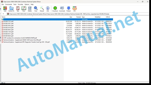
00 0300 725 2.pdf
00 0302 343 1.pdf
00 0302 565 2.pdf
00 0302 614 0.pdf
00 0302 805 2.pdf
00 0303 118 0.pdf
00 0303 815 1.pdf
00 0305 863 0.pdf
CHP-numbers for connectors CLAAS HARNESS PARTS.pdf
Technical Systems – Supplement CEMIS 1200 Fusion One SPA.pdf
Technical Systems – Supplement DTC Diagnostic Trouble Code Typ C89 – C83.pdf
00 0302 343 1.pdf:
PROFI CAM 3
Table of contents
General information
Marking of warnings and hazard prevention notes
First-aid measures
CCN explanation
CCN (CLAAS Component Number)
Electric system standard
Overview
Hydraulic system standard
Overview
CCN (CLAAS Component Number)
10 Electrical / Electronic equipment
1030 Board computer / Indicators
Camera system
Description of function
1097 Testing / Measuring / Adjusting
Testing / measuring / adjusting the PROFI CAM
Checking the fuse in the video channel select box (C102)
Testing the video camera connector (C055)
1098 Fault / remedy
Fault / remedy PROFI CAM
The video monitor (C101) shows no image or cannot be switched on (indicator light fails to light up)
Video monitor (C102) displays a blue image either permanently or temporarily
The video monitor image is blurred
Replacing the fuse in the video channel select box (C102)
Connection and connecting cable with video camera (C055)
00 0302 565 2.pdf:
Sensor system
Table of contents
CCN explanation
CCN (CLAAS Component Number)
Electric system standard
Overview
Hydraulic system standard
Overview
CCN (CLAAS Component Number)
Introduction
Safety rules
Safety and hazard information
10 Electrical / Electronic equipment
1097 Testing / Measuring / Adjusting
Test report of the angle sensor (0011780.x)
Application of test report
Required tools
Test report of the angle sensor (0011780.x)
Testing / Measuring / Adjusting of angle sensor (0011780.x)
1. Reason for test
2. Mechanical test of angle sensor
3. Electric test with CDS
4. Electric test with multimeter
5. Mechanical test of connecting cable
Completing the machine
Test report of position and speed sensors
Application of test report
Required tools
Sensor variants
Part numbers of speed sensors
Part number of position sensor
Test report of position and speed sensors
Testing / measuring / adjusting of position and speed sensors
1. Reason for test
2. Mechanical test
3. Electric test with CDS
4a. Installation dimensions
Check of installation dimension
Installation dimensions of gearbox speed sensor (0011 799.x) and cam speed sensor (0011 810.x)
Installation dimension of position sensor (0011 815.x)
4b. Installation position
Centring of sensor
Metal-free zone
5. Electric test with multimeter
Voltage measurement
Direction of rotation and speed sensor (0011 605.x)
Measured values table
6. Mechanical test of connecting cable
Completing the machine
Test report of the urea sensor (00 0773 207 x)
Application of test report
Required tools
Parts number of the urea sensor
Test report of the urea sensor
Testing / measuring / adjusting urea sensor
1. Reason for test
2. Mechanical test
3. Mechanical test of connecting cable
4. Electric test with multimeter
5. Component test with the CDS
00 0305 863 0.pdf:
LEXIONJAGUARXERION
Table of contents
Introduction
Notes on the manual
Validity of manual
Information about this Technical Systems Manual
Identifying warnings
Hazard signs
Signal word
01 Engine
0125 Injection / Fuel system
Injection / fuel system
Required tools and aids
Line valves for connecting to the engine
Valves and adapters for tank feed and return lines
Measuring setup (possible variant)
Test procedure
A – Leakage test of tank return line and possibly of tank suction line
B – Leakage test of feed lines (possibly including fuel sediment filter)
C – Test of non-return valve in the line (if provided)
D – Leakage test of return lines (possibly including the fuel cooler)
E – Leakage test of fuel sediment filter
F – Leakage test of engine
Steps 1 – 3
Fuel diagrams
Remarks about the circuit diagrams
LEXION fuel diagram
Key to diagram
JAGUAR with Mercedes-Benz OM47x LA
Key to diagram
JAGUAR with MAN D2862 (V12)
Key to diagram
CHP-numbers for connectors CLAAS HARNESS PARTS.pdf:
CLAAS HARNESS PARTS
Table of contents
10 Electrical / Electronic equipment
1081 Overview of connectors
CLAAS HARNESS PARTS (CHP)
Technical Systems – Supplement CEMIS 1200 Fusion One SPA.pdf:
01_Supplement to the system technology documents C8x_new
1_Validity Fusion one
4_SCM 110a CAN5
5_Table SCM 110a CAN5
6_SCM 330a Fusion One
7_Table SCM 330a Fusion one
Technical Systems – Supplement DTC Diagnostic Trouble Code Typ C89 – C83.pdf:
DTC: C89 – C83
General information
Marking of warnings and hazard prevention notes
First-aid measures
92 Diagnosis
9210 Error codes machine
FMI (Failure Mode Indicator)
FMI 00 (Signal too high)
FMI 01 (Signal too low)
FMI 02 (Erratic signal)
FMI 03 (Voltage too high)
FMI 04 (Voltage too low)
FMI 05 (Current too low)
FMI 06 (Current too high)
FMI 07 (Mechanical failure)
FMI 08 (Abnormal frequency signal)
FMI 09 (Communication error)
FMI 10 (Rate of signal change too fast)
FMI 11 (multiple faults)
FMI 12 (ECU defective)
FMI 13 (Signal outside of calibration range)
FMI 16 (Parameter not available)
FMI 17 (ECU not responding)
FMI 18 (Power supply failure)
FMI 19 (Software conditions not met)
FMI 95 (no signal change)
FMI 96 (CAN Bus system defective)
FMI 97 (Erratic condition)
FMI 98 (Warning)
FMI 99 (Info)
John Deere Repair Technical Manual PDF
John Deere Repair Technical Manual PDF
John Deere DF Series 150 and 250 Transmissions (ANALOG) Component Technical Manual CTM147 05JUN98
John Deere Repair Technical Manual PDF
John Deere Repair Technical Manual PDF
John Deere POWERTECH E 4.5 and 6.8 L Diesel Engines TECHNICAL MANUAL 25JAN08
John Deere Parts Catalog PDF
John Deere Tractors 7500 Parts Catalog CPCQ26568 30 Jan 02 Portuguese
John Deere Repair Technical Manual PDF
John Deere Diesel Engines PowerTech 4.5L and 6.8L – Motor Base Technical Manual 07MAY08 Portuguese
John Deere Repair Technical Manual PDF
John Deere Transmission Control Unit Component Technical Manual CTM157 15JUL05
John Deere Repair Technical Manual PDF
John Deere Application List Component Technical Manual CTM106819 24AUG20
John Deere Repair Technical Manual PDF
John Deere 16, 18, 20 and 24HP Onan Engines Component Technical Manual CTM2 (19APR90)

