Claas Lexion 570 Montana (581) Combines Technical System FR
$150.00
- Model: Lexion 570 Montana (581) Combines
- Type Of Manual: Technical System
- Language: FR
- Format: PDF(s)
- Size: 92.5 MB
File List:
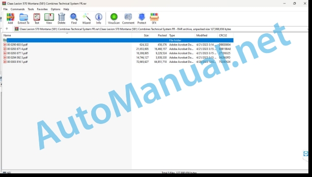
00 0290 603 0.pdf
00 0293 671 4.pdf
00 0293 677 1.pdf
00 0294 092 3.pdf
00 0303 816 1.pdf
00 0290 603 0.pdf:
Contents
Introduction
Validity of the notice
Overview
Connection diagrams
13c Scattering of straw and chaff. Radial spreader with spreading characteristics
13c Scattering of straw and chaff. Radial spreader with spreading characteristics
Designations
Table of measured values
Description of operation
Scattering mode switch U039
Description of operation
Sheet allocation
List of bindings
Wiring the modules
Module A51 – radial spreader
Designations
Pin Allocation
Alphabetical index
00 0293 671 4.pdf:
LEXION 570 – 520 Montana – Technical systems, Hydraulic system
1 General hydraulics
1.1 General hydraulics
1.1.1 Oil tank (general hydraulic system)
1.1.2 Hydraulic pumps
1.1.3 Hydraulic motors
1.1.4 Valves
1.2 General hydraulic system control plan
1.2.1 General hydraulic system control plan
LEXION-Montana 570-520 up to machine number 582 00051, 581 00027, 580 00028
1.2.2 General hydraulic system control plan
LEXION-Montana 570-520 – machine number 581 00027 to 581 00037
1.2.3 General hydraulic system control plan
LEXION-Montana 570-520 – machine number 582 00052 – 582 00153, 581 00038 – 581 00162, 580 00029 – 580 00071
1.2.4 General hydraulic system control plan
LEXION-Montana 570-520 from machine number 582 00154, 581 00163, 580 00072
Designations
1.3 Multifunction clutch
2 Steering hydraulics
2.1 Hydraulic steering control plans
2.1.1 Hydraulic steering control plan with AUTOPILOT concave adjustment with filling valve – LEXION 600 / 580 / 570
2.1.2 Hydraulic steering control plan with AUTOPILOT concave adjustment without filling valve – LEXION 560-510
2.1.3 Hydraulic steering control plan without AUTOPILOT
2.2 Management
2.2.1 Management function
2.2.2 Steering function – Two-stage orbitrol
2.3 AUTOPILOT
2.3.1 Right/left AUTOPILOT function
3 Operating hydraulics
3.1 Plan of hydraulic operating controls
3.1.1 Plan of hydraulic operating controls
3.1.2 Plan of hydraulic operating controls
3.1.3 Plan of hydraulic operating controls
3.2 Main valve up/down of the front tool
3.2.1 Main valve
3.3 Adjusting the concave
3.3.1 Concave adjustment – LEXION 600 / 580 / 570 Hydropneumatic overload system with filling valve
3.3.2 Adjustment of the LEXION 560 – 510 concave hydraulic overload system without filling valve
3.4 Adjusting the mixer speed
3.4.1 Adjusting the mixer rotation speed
3.5 Pivoting of the spreading fan / radial spreader / swath flap
3.5.1 Pivoting of the radial spreader
3.5.2 Pivoting the swath flap
3.6 Pivoting the hopper discharge chute
3.6.1 Pivoting the hopper discharge chute
3.7 Adjusting the rotor speed
3.7.1 Adjusting the rotor speed
3.8 Quick stop of the front tool
3.8.1 Quick stop of the front tool
3.9 Locking the cutting spring
3.9.1 Locking the cup spring
3.10 Adjusting the speed of the feed channel / front tool
3.10.1 Adjusting the rotation speed of the feed channel / front tool
3.11 Opening / closing of the grain hopper (hydraulic) Aid for emptying the grain hopper
3.11.1 Opening / closing of the grain hopper (hydraulic)
3.11.2 Hopper emptying assistance
3.12 Adjusting the front tool
3.12.1 AUTO-CONTOUR (CAC) – Transverse adjustment of the LEXION Montana front tool up to machine number 582 00051, 581 00037, 580 00028
3.12.2 AUTO-CONTOUR (CAC) – Transverse adjustment of the LEXION Montana front tool from machine number 582 00052, 581 00038, 580 00029
3.13 Inversion of the front tool
3.13.1 Inversion of the front tool – LEXION Montana 570-520
3.14 Front tool damping system
3.14.1 Front tool cushioning – with front tool cylinder with spring
3.14.2 Front tool cushioning – with front tool cylinder without spring (CAC II)
3.15 Half-track tension
3.15.1 Half-track tension
3.15.2 Half-track tension
3.16 Adjusting the cutting frame (Montana)
3.17 Cutting angle adjustment (Montana)
3.18 Operating brake
3.18.1 Filling the pressure accumulator – LEXION 600 Terra Trac, LEXION Montana
4 Low pressure hydraulic system
4.1 Low pressure hydraulic system – basic functions
4.1.1 Control plan for the LEXION 600 low pressure hydraulic system (wheeled machine)
4.1.2 Control plan for the LEXION 600 Terra Trac low pressure hydraulic system
4.1.3 Hydraulic control plan for the LEXION 580-510 low pressure circuit
4.1.4 Low pressure circuit pressure limiter
4.1.5 Low pressure hydraulic system distributors
4.1.6 Hydraulic cylinder of the low pressure circuit
4.1.7 Control of the 3-D cleaning box
4.1.8 Lubrication of hopper discharge chain
4.2 Low pressure hydraulic system – Montana auxiliary functions
4.2.1 Plan of low pressure hydraulic controls LEXION Montana 570-520
4.2.2 Solenoid valves of the low pressure hydraulic system – LEXION-Montana 570-520
4.2.3 Hydraulic cylinder of the low-pressure system
4.2.4 Position of the components of the low pressure hydraulic system – LEXION-Montana
5 Electro-hydraulic control (EHS)
5.1 Control plan for the LEXION Montana 570-520 electrohydraulic drive
6 Straw and chaff spreader
6.1 Straw spreader and chaff chopper
6.1.1 Hydraulic control plan for the straw fan and chaff chopper
6.1.2 Driving the straw spreader and chaff chopper
6.2 Radial spreader
6.2.1 Radial spreader control plan
6.2.2 Radial spreader for the working/transport position
6.2.3 Radial spreader in transport position
6.2.4 Driving the spreading plate of the radial spreader
7 Rotary sieve drive
7.1 Rotary sieve
7.1.1 Hydraulic control plan for the rotary screen
7.1.2 Rotary screen drive
8 Hydrostatic system
8.1 Hydrostatic system – Montana
8.1.1 Hydrostatic system control plan – Montana
up to machine number 582 00051, 581 00037, 580 00028
8.1.2 Hydrostatic system control plan – Montana
Machine number 582 00052 – 582 00153, 581 00038 – 581 00162, 580 00029 – 580 00071
8.1.3 Hydrostatic system control plan – Montana
from machine number 582 00154, 581 00163, 580 00072
8.1.4 Hydrostatic system control pressure
8.1.5 Pump block
8.1.6 Engine block
8.1.7 Hydrostatic system brake restrictor (HBM) control – external brake function
up to machine number 582 00051, 581 00037, 580 00028
8.1.8 Hydrostatic Brake Restrictor (HBM) Control – Integrated Restrictor
from machine number 582 00052, 581 00038, 580 00029
8.2 4-trac drive (4-wheel drive drive)
8.2.1 MUD HOG valve block
8.2.2 POCLAIN radial piston engine
8.2.3 4-Trac Overdrive
9 Axle hydraulics (Montana)
9.1 Axle hydraulic system control plan
9.1.1 Control plan for the hydraulic system of the LEXION-Montana 570-520 axle up to machine number 582 00051, 581 00037, 580 00028
9.1.2 Control plan for the hydraulic system of the LEXION-Montana 570-520 axle Machine number 582 00052 – 582 00153, 581 00038 – 581 00162, 580 00028 – 580 00071
9.1.3 Control plan for the hydraulic system of the LEXION-Montana 570-520 axle from machine number 582 00154, 581 00163, 580 00072
9.2 Axle control (Montana)
9.2.1 Axle control – cut-off valve / pressure relief valve up to machine number 582 00051, 581 00037, 580 00028
9.2.2 Axle control – cut-off valve / pressure relief valve from machine number 582 00052, 581 00038, 580 00029
9.2.3 Axle control – raising/lowering the axle, increasing the oil volume to machine number 582 00051, 581 00037, 580 00028
9.2.4 Axle control – axle raise/lower from machine number 582 00052, 581 00038, 580 00029
9.3 Gear shifting assistance (Montana)
9.4 Position of axle control components
10 Brake system
10.1 Hydraulic brake system LEXION-Montana 570-520
11 Standard fit
11.1 Hydraulic control plan for the standard cut
11.2 Vertical adjustment of the reel (standard cut)
11.3 Horizontal adjustment of the reel (standard cut)
11.4 Adjusting the reel speed (standard cut)
11.5 Driving rapeseed saws (standard cutting)
12 Vario Cup
12.1 Vario cutting hydraulic control plan
12.2 Vertical adjustment of the reel (Vario cut)
12.3 Horizontal adjustment of the reel (Vario cut)
12.4 Adjusting the reel speed (Vario cut)
12.5 Adjusting the cutting deck (Vario cutting)
12.6 Driving the rapeseed saws (Vario cutting)
13 Folding cup
13.1 Plan of the hydraulic controls of the folding cutter
13.2 Vertical adjustment of the reel (folding cut)
13.3 Horizontal adjustment of the reel (folding cut)
13.4 Adjusting the reel speed (folding cut)
13.5 Folding the cup
14 Conspeed corn header
14.1 Hydraulic control plan for the Conspeed corn header / 6-row (type 908)
14.2 Hydraulic control plan for the Conspeed corn header / 8-row (type 907)
14.3 Folding the picking units / adjusting the picking plates of the Conspeed corn header
14.4 Adjusting the reel speed (Conspeed corn header)
15 MaxFlex cutting bar
15.1 MaxFlex cutting control plan
15.2 Vertical adjustment of the reel (MaxFlex cut)
15.3 Horizontal adjustment of the reel (MaxFlex cut)
15.4 Adjusting the reel speed (MaxFlex cut)
15.5 Locking the cutting deck (MaxFlex cutting)
Component coordination scheme
Component coordination scheme
Keyword index
0293 671.4
00 0293 677 1.pdf:
Technical systems – Electrical system LEXION 570 – 520 MONTANA, up to machine number 582 00092, 581 00082, 580 00049
Construction of electrical plans
Power plant
Power plant (LEXION 600-510)
Montana 570-520 power station – with external control Montana
Montana 570-520 power station – with integrated Montana control
Module pinout layout
Module A6 – Air conditioning
Module A7 – Cabin fan speed regulator
Module A8 – AUTOCONTOUR (CAC)
Module A9 – Autopilot (ATP)
Module A10 – Bordinformator (BIF/CAB)
Module A12 – Rotation speed safety (DZW)
Module A13 – Flow Control (DKG)
Module A15 – Electronic engine control CATERPILLAR (CAT C13,C12,C10, C9, 3126B)
Module A15 – Electronic engine control CATERPILLAR (CAT C 6.6)
Module A15 – electronic engine control DAIMLER-CHRYSLER (DC)
Module A17 – Adaptation of the ADM DAIMLER-CHRYSLER (DC) engine
Module A16 – Reel adjustment
Module A21 – Quantimeter
Module A25 – Adjusting the grids
Module A27 – VARIO
Module A28 – Spreader fan (VGS)
Module A30 – Terminal
Module A33 – Sidefinder
Module A34 – Hopper emptying
Module A35 – Montana 570-520 distributor – with external Montana control
Module A36 – Montana 570-520 speed preselection – with external Montana control
Module A37 – Electrohydraulic control (EHS) – 3-speed transmission
Module A37 – Electrohydraulic control (EHS) – 2-speed transmission
Module A38 – Rotor (RIO)
Module A42 – MONTANA GEN II- module with integrated Montana control (from machine number 582 00052, 581 00027 and 580 00029)
Module A45 – Hydrostatic System Brake (HBM) Restrictor
Module A46 – Adjustment of the spreading plate (RIO)
Module A49 – Hydrostatic System Module (EFA)
Module A51 – Radial spreader
Module A65 – Pilot GPS terminal
Module A66 – GPS Pilot Module (GPB)
Electrical plans 01a – 50a
01a Main voltage supply, diesel engine starter
01s Main voltage supply, diesel engine starter, Montana 570-520
02a Starting the diesel engine, adjusting the speed of the diesel engine – CAT C12, C10, C9, 3126B
02b Starting the diesel engine, adjusting the speed of the diesel engine – DC 502 LA
02c Starting the diesel engine, adjusting the speed of the diesel engine – DC 502 LA, with electrohydraulically controlled hydrostatic drive (EFA)
02d Starting the diesel engine, adjusting the speed of the diesel engine – CAT C6.6
02e Starting the diesel engine, adjusting the speed of the diesel engine – CAT C13 ACERT, C9 ACERT (TIER III)
02s Diesel engine start, diesel engine speed adjustment – CAT C12, C10, C9, 3126B, Montana 570-520 – with external Montana control
02t Diesel engine start, diesel engine speed adjustment – CAT C12, C10, C9, 3126B, Montana 570-520 – with integrated Montana control
03a Diesel engine safety
04a Road driving control, circuit breaker valve
04b Road driving control, cut-off valve – with electrohydraulically controlled hydrostatic drive (EFA)
04s Road driving release, operating hydraulic system cut-off valve, Montana 570-520 – with external Montana control
04t Road driving release, operating hydraulic system cut-off valve, Montana 570-520 – with integrated Montana control
05a Dashboard, keyboard, rotary switch, printer
05b Dashboard, keypad, rotary switch, printer – with electrohydraulically controlled hydrostatic drive (EFA)
06a CAN-Bus, voltage supply module, with CATERPILLAR diesel engine – C12, C10, C9, 3126B
06b CAN-Bus, power supply module, with Daimler diesel engine – Chrysler DC 502 LA – without electrohydraulically controlled hydrostatic drive (EFA)
06c CAN-Bus, power supply module, with CATERPILLAR diesel engine – C13 ACERT (TIER III) – with electrohydraulically controlled hydrostatic drive (EFA)
06d CAN-Bus, power supply module, with Daimler diesel engine – Chrysler DC 502 LA, – with electrohydraulically controlled hydrostatic drive (EFA)
06e CAN-Bus, voltage supply module, with CATERPILLAR diesel engine – C 6.6
06f CAN-Bus, voltage supply module, with CATERPILLAR diesel engine – C9 ACERT (TIER III)
06s CAN-BUS, module voltage supply, Montana 570-520 – with external Montana control
06t CAN-BUS, module voltage supply, Montana 570-520 – with integrated Montana control
07a Beater clutch
08a Adjusting the concave / beater variator
09a Adjusting the rotor flaps / rotor variator
10a Fan variator
11a Adjusting the grids
12a Adjusting the spreading plate
13a Straw and chaff spreader, spreading fan – LEXION 580
13b Straw and chaff spreader
14a Pivoting of the hopper discharge chute
15a Emptying the grain hopper / helping to empty the grain hopper
16a Control of rapeseed saws
17a Front tool and reversing drive
17b Front implement and reversing drive – with electrohydraulically controlled hydrostatic system (EFA)
17s Tool drive, reversing drive, front tool quick stop, Montana 570-520 – with external Montana control
18a Front tool variator
19a Straw chopper
19b Straw chopper – Radial spreader without chaff ejector fan
19c Straw chopper – Radial spreader with chaff ejection fan
20a Raising/lowering the front tool, transverse adjustment
20b Front implement raise/lower, transverse adjustment – with electrohydraulically controlled hydrostatic drive (EFA)
20s Raising / lowering of the tool, transverse adjustment, Montana 570-520
21a Reel Adjustment, Standard Cut, MaxFlex Soybean Front Implement
21b Adjusting the VARIO cutting reel
21c Adjusting the folding cup reel
21d Folding the corn picker, adjusting the picking plates, corn auger
21st Rake up training – Training, adjustment of the swath packer
22a Reel variator
23a Adjusting the cutting deck (Vario), folding the cutting
23b Adjusting the cutting deck – MaxFlex
24a AUTOCONTOUR (CAC)
25a Safety of the rotation regime
26a Machine safety
26b Machine safety – with electrohydraulically controlled hydrostatic system (EFA)
26s Machine safety, Montana 570-520 – with external Montana control
26t Machine safety, Montana 570-520 – with integrated Montana control
27a Quantimeter / Grainmeter
28a AUTOPILOT – Laser system
28b AUTOPILOT – Sensor system
28c AUTOPILOT – GPS steering
29a Flow control
30a Grain hopper opening/closing (electric), grain hopper filling indicator, rotating beacon
30b Grain hopper opening/closing (hydraulic), grain hopper filling indicator, rotating beacon
31a Suspension of the front tool
32a 4-wheel drive control, auxiliary tank
32b 4-wheel drive control – Overdrive, auxiliary tank
32c 4-wheel drive control, auxiliary tank – with electrohydraulically controlled hydrostatic system (EFA)
32d 4-wheel drive control – Overdrive, auxiliary tank – with electrohydraulically controlled hydrostatic system (EFA)
33a Cutting spring lock
36a Flashing device (Europa)
36b Flashing device (USA)
37a Windshield wiper, windshield washer system
38a Air conditioning
38b Air conditioning automation
39a Cabin comfort equipment – driver’s seat
40a Auxiliary sockets, fuse test
41s Axle control and front implement control, Montana 570-520- with external Montana control
41t Axle control and front implement control, Montana 570-520 – with integrated Montana control
42a Hydrostatic system control and brake
42b Hydrostatic system control and brake – with electrohydraulically controlled hydrostatic drive (EFA) LEXION 600 TerraTrac
42s Hydrostatic system control and brake, Montana 570-520 with external Montana control
42t Hydrostatic and brake control, Montana 570-520 – with integrated Montana control
43a Electrohydraulically controlled hydrostatic system (EFA)
44a Electro-hydraulic control, 3-speed transmission
44b Electro-hydraulic control, 2-speed transmission
45a Main switch for lighting, rear lights, positioning ligh6a headlights, high beams, high beam switching
47a Work lighting I
48a Work lighting II
49a Lighting of the return to the drums, the grids, the hopper, buzzer, brake lights
49b Lighting of the return to the drums, grids, hopper, buzzer, brake lights – with hydrostatic system with electrohydraulic control (EFA)
50a Instrument lighting, radio, mirror adjustment
Coordination diagram
Keyword index
0293 677.1
00 0294 092 3.pdf:
LEXION 570 – 520 Montana From machine number 582 00093, 581 00083, 580 00050 Technical systems, Electrical system
Construction of electrical plans
Power plant
Module pinout layout
Module A6 – Air conditioning
Module A7 – Cabin fan speed regulator
Module A8 – AUTOCONTOUR (CAC)
Module A9 – Autopilot (ATP)
Module A10 – On-board informant (BIF/CAB)
Module A12 – Rotation speed safety (DZW)
Module A13 – Flow Control (DKG)
Module A15 – CATERPILLAR electronic engine control (CAT C13, C12, C10, C9, 3126B)
Module A15 – Electronic engine control CATERPILLAR (CAT C 6.6)
Module A15 – electronic engine control DAIMLER-CHRYSLER (DC)
Module A17 – Adaptation of the ADM DAIMLER-CHRYSLER (DC) engine
Module A16 – Reel adjustment
Module A21 – Quantimeter
Module A25 – Adjusting the grids
Module A27 – VARIO
Module A28 – Spreader fan (VGS)
Module A30 – Cebis Terminal
Module A33 – Sidefinder
Module A34 – Hopper emptying
Module A37 – Electrohydraulic control (EHS) – 3-speed transmission
Module A38 – Rotor (RIO)
Module A39 – Feed adjustment
A42 module • MONTANA GEN II module • X1 (42 poles)
Module A46 – Adjustment of the spreading plate (RIO)
Module A49 – Hydrostatic System Module (EFA)
Module A51 – Radial spreader
Module A65 – Pilot GPS terminal
Module A66 – GPS Pilot Module (GPB)
Module A83 – 4-Trac validation module
Electrical plan 01a-50a
01mMain voltage supply, diesel engine starter
02aStarting the diesel engine, adjusting the speed of the dieengine
0arting the diesel engine, adjusting the speed of the diesel engine
02cStarting the diesel engine, adjusting the speed of the diesel engine
02dStarting the diesel engine,Adjusting the speed of the diesel engine
03aDiesel engine safety
04m Road driving control, circuit breaker valve
05mDashboard, keyboard, rotary switch, printer
06mCAN-Bus, voltage supply module
07abeater clutch
08aAdjusting the concave/beater variator
09aAdjusting the rotor hatches/rotor variator
10aFan variator
11aAdjusting the grids
12aAdjustment of the spreading plate
13bStraw and chaff spreader
14aPivoting of the hopper discharge chute
15aEmptying the grain hopper / assisting with emptying the grain hopper
16aOrdering rapeseed saws
17aFront tool drive, reversing drive
18aFront tool variator
19aStraw chopper
19bStraw chopper
20aRaise/lower front tool, transverse adjustment
21aAdjusting the reel
21bAdjusting the reel
21cConspeed corn picker
22aReel variator
23aAdjusting the cutting deck (Vario), folding the cutting
24aAUTOCONTOUR (CAC)
25aSafety of the rotation regime
26mMachine safety
27aQuantimeter / Grainmeter
28aAUTOPILOT
28bAUTOPILOT
28cAUTOPILOT
29aFlow control
30aOpening / closing of the grain hopper (electric),
Coordination diagram
00 0294 092.3
John Deere Repair Technical Manual PDF
John Deere Repair Technical Manual PDF
John Deere Repair Technical Manual PDF
John Deere 16, 18, 20 and 24HP Onan Engines Component Technical Manual CTM2 (19APR90)
John Deere Repair Technical Manual PDF
John Deere Repair Technical Manual PDF
John Deere Repair Technical Manual PDF
John Deere 18-Speed PST Repair Manual Component Technical Manual CTM168 10DEC07
John Deere Repair Technical Manual PDF
John Deere Repair Technical Manual PDF
John Deere Application List Component Technical Manual CTM106819 24AUG20

