Claas Lexion 600 (589) Combines Repair Manual FR
$100.00
- Model: Lexion 600 (589) Combines
- Type Of Manual: Repair Manual
- Language: FR
- Format: PDF(s)
- Size: 165 MB
File List:
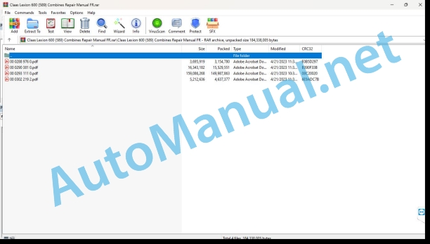
00 0288 976 0.pdf
00 0290 381 0.pdf
00 0293 111 0.pdf
00 0302 219 2.pdf
00 0288 976 0.pdf:
LEXION 770-405
Contents
Introduction
General informations
Validity of the notice
Use of the instructions
Texts and illustrations
Plan with module structure
Seek and find
Steering Specifications
Abbreviations
Specialized terminology
Security
General informations
To respect
Warning pictogram
Signal word
General safety and accident prevention instructions
General safety and accident prevention regulations, combine harvester
First aid measures
Exit the machine
Battery cut-off switch
Stop the machine
02 Transmission – Clutch – Cardan shaft
0210 Oscillation damper
Vibration damper
Technical characteristics
Preparing for work
To set down
Vibration damper
Technical characteristics
Preparing for work
To set down
Vibration damper
Technical characteristics
Preparing for work
To set down
00 0290 381 0.pdf:
Contents
1 Introduction
1.1 General advice
1.1.1 Validity of the notice
2 Power channel
2.1 Power channel
2.1.1 HP anti-slip strips – supply channel, replace
3 Straw deposit
3.1 Ball spreader
3.1.1 LEXION 600 – 560 ball spreader / ball throwing fan (types 589 – 584), overview
3.1.2 LEXION 600 – 560 radial spreader (types 589 – 584), overview
3.2 Straw spreader
3.2.1 Overview of the straw chopper
4 Workouts
4.1 Drive belts / drive chains
4.1.1 Left drive diagram (LEXION 600 with JET STREAM cleaning system)
4.1.2 Right-hand drive layout (LEXION 600 with JET STREAM cleaning system)
4.1.3 Left-hand drive layout (LEXION 580 with standard cleaning system)
4.1.4 Right-hand drive layout (LEXION 580 with standard cleaning system)
4.1.5 Left-hand drive layout (LEXION 570 with standard cleaning system)
4.1.6 Right-hand drive layout (LEXION 570 with standard cleaning system)
4.1.7 Left-hand drive layout (LEXION 570 with JET STREAM cleaning system)
4.1.8 Right-hand drive layout (LEXION 570 with JET STREAM cleaning system)
4.1.9 Left drive diagram (LEXION 560 – 510 with standard cleaning system)
4.1.10 Right-hand drive scheme (LEXION 560 – 510 with standard cleaning system)
4.1.11 Remove the belt (R26)
4.1.12 Install the belt (R26)
4.1.13 Adjust the belt (R26)
4.2 Fan drive, JET STREAM LEXION 570 cleaning system
4.2.1 Overview of fan drive (electric) from machine No. …
4.2.2 Overview of fan drive (spring loaded) from machine No….
4.2.3 Overview of the fan drive from machine No….
4.3 Special tool fan drive, JET STREAM LEXION 570 cleaning system
4.3.1 Disassemble the fan drive (spring loaded) from machine No…
4.3.2 Disassemble the fan variator (spring loaded) from machine No…
4.4 Front tool drive
4.4.1 Overview, belt (R2)
4.4.2 Remove the drive pulley, belt (R2) from the machine No. …
4.4.3 Overview of drive pulley, belt (R2) from machine No. …
4.4.4 Install the drive pulley, belt (R2) from the machine No. …
4.4.5 Belt overview (R3) (with front tool variator)
4.4.6 Remove the front implement variator (hydraulic) from the machine No. …
4.4.7 Overview of the front implement variator (hydraulic) from the machine No….
4.4.8 Install the front implement variator (hydraulic) from the machine No. …
4.4.9 Belt overview (R3) (with front tool step drive)
4.4.10 Overview, belt (R26)
4.4.11 Remove the drive pulley, belt (R26)
4.4.12 Overview of drive pulley, belt (R26)
4.4.13 Install the drive pulley, belt (R26)
4.4.14 Remove the driven pulley, belt (R26)
4.4.15 Overview of driven pulley, belt (R26)
4.4.16 Install the driven pulley, belt (R26)
4.4.17 Overview of tensioner pulley, belt (R26)
4.5 Special tool Front tool drive
4.5.1 Install the drive pulley, belt (R2) from the machine No. …
4.5.2 Remove the front implement variator (hydraulic) from the machine No. …
4.5.3 Install the front implement variator (hydraulic) from the machine No. …
4.5.4 Install the drive pulley, belt (R26)
4.5.5 Remove the driven pulley, belt (R26)
4.5.6 Install the driven pulley, belt (R26)
4.6 Straw pump drive
4.6.1 Remove the driven pulley, belt (R5) from the machine No….
4.6.2 Overview of driven pulley, belt (R5) from machine No….
4.6.3 Install the driven pulley, belt (R5) from machine No….
4.7 Special tool for driving the straw puller
4.7.1 Remove the driven pulley, belt (R5) from the machine No….
5 Axles, pneumatic
5.1 Steering axle
5.1.1 Removing the steering axle / CLAAS 4-TRAC axle / standard cleaning system
5.1.2 Install the steering axle / CLAAS 4-TRAC axle, standard cleaning system
5.1.3 Remove steering axle / CLAAS 4-TRAC axle / ACTIVE TRAC axle, JET STREAM cleaning system
5.1.4 Install the steering axle / CLAAS 4-TRAC axle / ACTIVE TRAC axle, JET STREAM cleaning system
5.1.5 Overview of the steering axle (10T adjustable)
5.1.6 Overview of the steering axle (9.5T adjustable)
5.1.7 Overview of the steering axle (9T adjustable)
5.1.8 Overview of the steering axle (9T fixed)
5.1.9 Overview of the steering axle (8.5T adjustable)
5.1.10 Steering axle overview (7.5T fixed/adjustable)
5.1.11 Overview of the steering axle (7T adjustable)
5.2 Drive wheel steering axle
5.2.1 Remove the engine support, ACTIVE TRAC axle (11T)
5.2.2 Overview of motor support, ACTIVE TRAC axle (11T)
5.2.3 Install the engine support, ACTIVE TRAC axle (11T)
5.2.4 Remove the ACTIVE TRAC axle gearbox (11T)
5.2.5 Install the ACTIVE TRAC axle gearbox (11T)
5.2.6 Overview of the ACTIVE TRAC axle (11T)
5.2.7 Overview of the CLAAS 4-TRAC (11T) axle
5.2.8 Overview of the CLAAS 4-TRAC axle (9T / 10T)
5.2.9 Overview of the CLAAS 4-TRAC axle (9.5T)
5.3 Special tool for drive wheel steering axle
5.3.1 Install the engine support, ACTIVE TRAC axle (11T)
6 Hydraulics
6.1 General
6.1.1 Bleed the hydrostatic system with mechanical-hydraulic transmission
6.1.2 Bleed the air in the hydrostatic system with electro-hydraulic transmission
6.1.3 Bleeding the air from the CLAAS 4-TRAC system with mechanical-hydraulic transmission
6.2 General hydraulic system special tool
6.2.1 Bleed the air from the hydrostatic system with mechanical-hydraulic transmission
6.2.2 Bleeding air from the hydrostatic system with electro-hydraulic transmission
6.3 Hydraulic motors
6.3.1 Remove the radial spreader motor (241 / 242)
6.3.2 Install the radial spreader motor (241 / 242)
6.3.3 Remove the motor from the CLAAS 4-TRAC axle (203 / 204)
6.3.4 Install the CLAAS 4-TRAC axle motor (203 / 204)
6.3.5 Remove the engine, ACTIVE TRAC axle (2063 / 2064)
6.3.6 Install the ACTIVE TRAC axle motor (2063 / 2064)
6.3.7 Overview of the hydraulic cylinder (same ratio cylinder) steering (323)
6.4 Special hydraulic motor tool
6.4.1 Install the radial spreader motor (241 / 242)
6.5 Hydraulic cylinder
6.5.1 Overview of the hydraulic cylinder (same ratio cylinder) steering (323)
7.1 Transfer case
7.1.1 Disassembly of the transfer case
7.1.2 Overview of the distributor box
7.2 Special transfer case tool
7.2.1 Disassemble the transfer case
7.2.2 Disassemble the transfer case
7.2.3 Assemble the transfer case
7.2.4 Assemble the transfer case
Alphabetical index
00 0302 219 2.pdf:
LEXION 770-405
Contents
Introduction
General informations
Validity of the notice
Use of the instructions
Texts and illustrations
Plan with module structure
Seek and find
Steering Specifications
Abbreviations
Specialized terminology
Tightening torques
Tightening torques for metric coarse threads
Tightening torques for metric fine pitch threads
Tightening torques for hydraulic screw connections with cutting ring DIN 3861
Security
General informations
To respect
Warning pictogram
Signal word
General safety and accident prevention instructions
General safety and accident prevention regulations, combine harvester
First aid measures
Deposit of harvested product / Deposit of straw
Exit the machine
Adjustment and maintenance work
Risk of injury from hydraulic fluid
Battery cut-off switch
Stop the machine
08 Orders
0841 Threshing gear control
Driven Pulley, Belt (R52)
Technical characteristics
Preparing for work
Special tool
Disassemble
To assemble
To set down
Lubrication interval
0842 Separation command
Driven Pulley, Belt (R41)
Technical characteristics
Preparing for work
Special tool
Disassemble
To assemble
To set down
Lubrication interval
John Deere Repair Technical Manual PDF
John Deere Repair Technical Manual PDF
John Deere Repair Technical Manual PDF
John Deere 18-Speed PST Repair Manual Component Technical Manual CTM168 10DEC07
John Deere Repair Technical Manual PDF
John Deere Diesel Engines PowerTech 4.5L and 6.8L – Motor Base Technical Manual 07MAY08 Portuguese
John Deere Repair Technical Manual PDF
John Deere Repair Technical Manual PDF
John Deere PowerTech M 10.5 L and 12.5 L Diesel Engines COMPONENT TECHNICAL MANUAL CTM100 10MAY11
John Deere Repair Technical Manual PDF
John Deere 16, 18, 20 and 24HP Onan Engines Component Technical Manual CTM2 (19APR90)
John Deere Repair Technical Manual PDF
John Deere Repair Technical Manual PDF
John Deere Repair Technical Manual PDF

