Claas Lexion 760-740 (C65) Combines Operator Manual FR
$50.00
- Model: Lexion 760-740 (C65) Combines
- Type Of Manual: Operator Manual
- Language: FR
- Format: PDF(s)
- Size: 158 MB
File List:
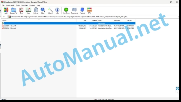
00 0292 445 2.pdf
00 0292 702 4.pdf
00 0292 702 4.pdf:
LEXION 760 MONTANALEXION 670 MONTANALEXION 630 MONTANA
Contents
1 About this user manual
1.1 Notes regarding the instructions
1.1.1 Validity of the notice
1.1.2 Notes on the supplement to the instructions for use
1.1.3 See the machine’s instructions for use
1.1.4 Symbols and remarks
1.1.5 Optional equipment
1.1.6 Qualified specialist workshop
1.1.7 Notes on maintenance
1.1.8 Notes regarding warranty
1.1.9 Technical characteristics
1.1.10 Spare parts and technical questions
2 Security
2.1 Recognize the warnings
2.1.1 Warning pictogram
2.1.2 Signal word
2.2 Safety tips
2.2.1 Travel mode with tilt compensation
2.3 Safety marking on the machine
2.3.1 Notes on warning pictograms
2.3.2 Cabin/driving station warning pictograms
3 Control and display elements
3.1 Cabin and driving position
3.1.1 Driving position
3.1.2 Contlonsole
3.1.3 MONTANA control panel
4 Technical characteristics
4.1 LEXION
4.1.1 Dimensions
Measurement conditions
4.1.2 Dimensions of the hopper drain tube
Measurement conditions
4.1.3 Turning diameter
Measurement conditions
4.1.4 Weight
Machine weight
Measurement conditions
Weight of equipment variants
4.1.5 Sound pressure level and vibrations
4.1.6 CATERPILLAR C-13 diesel engine
4.1.7 CATERPILLAR C-9.3 diesel engine
4.1.8 Undercarriage
Forward speed
Measurement conditions
Properties
Tire Pressure Charts
4.1.9 Track width
Channel table 1
Track width table 2
Route table 3
Route table 4
Route table 5
Route table 6
Track width table 7
4.1.10 Brakes
4.1.11 Management
4.1.12 Electrical system / electronic system
4.1.13 Harvest feeding
4.1.14 Power group
Measurement conditions
4.1.15 Threshing bodies
Properties of beaters
Pre-concave
Main concave
Trimming
4.1.16 Separation
Separation system
Rotor separation system
Shaker separation system
4.1.17 Cleaning
Cleaning system
Cleaning
4.1.18 Grain recovery
Hopper volume
Measurement conditions
Draining power (maximum)
Grain recovery
4.2 Operating consumables
4.2.1 Lubricants
5 Preparing the machine
5.1 Stop and immobilize the machine
5.1.1 Disconnect and secure the machine
5.2 Before commissioning
5.2.1 To be carried out before the first commissioning
5.3 Enter work and maintenance stations
5.3.1 Fold down the steps of the access ladder
5.3.2 Pivot the access ladder
5.4 Front tool
5.4.1 Install the cardan shaft
5.4.2 Remove the cardan shaft
5.4.3 Install the multiple coupling
5.4.4 Remove the multiple coupling
5.5 Chassis
5.5.1 Place the machine on jack stands
5.5.2 Place the machine on jack stands for the steering axle to swing
5.5.3 Procedure for adjusting the track width of the steering axle
5.5.4 Adjusting the track width of the steering axle
5.5.5 Adjusting the track width of the steering axle
5.5.6 Adjusting the track width of the steering axle
5.5.7 Adjusting the track width of the steering axle
5.5.8 Select bores at the adjusting element
5.6 Hydraulic system
5.6.1 Check the front tool relief pressure accumulator
5.7 Assembly parts and bodywork
5.7.1 Pre-assemble the access ladder
5.7.2 Install the access ladder
5.7.3 Install the weights for the folding front implements
5.8 Conveyor
5.8.1 Adjusting the feed chain in height
5.9 Threshing bodies
5.9.1 Beater hatch
6.1 Gearboxes, clutch and cardan shaft
6.1.1 Connect the differential lock
6.2 Chassis
6.2.1 Submit a report
6.2.2 Connect 4-TRAC*
6.2.3 Disconnect 4-TRAC*
6.2.4 MONTANA command
6.2.5 Controlling MONTANA functions
6.2.6 Switch on the MONTANA control
6.2.7 Lower the machine completely before traveling on the road
6.2.8 Bring the machine to neutral position
6.2.9 Manual axle control
6.2.10 Manual control of the front tool
6.2.11 Automatic service
6.2.12 Changing the cutting angle / inclination (cross regulation) in automatic operation
6.3 Brake
6.3.1 Activate the parking brake
6.3.2 Deactivate the parking brake
7 Faults and solutions
7.1 Chassis
7.1.1 Chassis, failure and solution
7.2 Gearboxes, clutch and cardan shaft
7.2.1 Mechanically shift the gearbox to neutral position
7.3 Brake
7.3.1 Mechanically release the parking brake
7.3.2 Mechanically release the parking brake
7.4 Electrical and electronic system
7.4.1 MONTANA command – failure and solution
7.5 Power group
7.5.1 Power group, fault and solution
8 Maintenance
8.1 Maintenance intervals
8.1.1 Before the start of the harvest
8.1.2 Every 10 operating hours or daily
8.1.3 Every 50 operating hours
8.1.4 Every 100 operating hours
8.1.5 Every 500 hours of service or annually
8.2 Lubrication plan
8.2.1 Lubricate the left side lubrication points every 100 operating hours
8.2.2 Lubricate the right side lubrication points every 100 operating hours
8.2.3 Lubricate the left side lubrication points every 500 operating hours
8.2.4 Lubricate the right side lubrication points every 500 operating hours
8.3 Chassis
8.3.1 Check the wheel fixation
Drive axle
Steering axle
8.3.2 Check the oil level of the differential and axle support
8.3.3 Drain the oil from the differential and axle support
Change the oil
Fill with oil
8.3.4 Check the oil level of the drive axle wheel connecting rods
8.3.5 Replacing the oil in the drive axle wheel connecting rods
Drain the oil
Pour the oil
8.3.6 Lubricate the pivot rings of the wheel connecting rods
8.3.7 Adjust the wheel connecting rod linkage
8.3.8 Check the oil level of the drive axle gearbox
8.3.9 Replacing the drive axle gearbox oil
Drain the oil
Pour the oil
8.3.10 Check the oil level in the drive axle axle box
8.3.11 Replace the oil in the drive axle axle box
Drain the oil
Pour the oil
8.4 Brake
8.4.1 Check foot brake pressure alarm display
8.5 Power group
8.5.1 Adjusting the feed chains of the MONTANA feed channel
8.5.2 Carry out basic cutting angle adjustment
8.5.3 Basic adjustment of the transverse position
John Deere Repair Technical Manual PDF
John Deere PowerTech M 10.5 L and 12.5 L Diesel Engines COMPONENT TECHNICAL MANUAL CTM100 10MAY11
John Deere Parts Catalog PDF
John Deere Harvesters 8500 and 8700 Parts Catalog CPCQ24910 Spanish
John Deere Parts Catalog PDF
John Deere Tractors 7500 Parts Catalog CPCQ26568 30 Jan 02 Portuguese
John Deere Repair Technical Manual PDF
John Deere Diesel Engines POWERTECH 2.9 L Component Technical Manual CTM126 Spanish
John Deere Repair Technical Manual PDF
John Deere 18-Speed PST Repair Manual Component Technical Manual CTM168 10DEC07
John Deere Repair Technical Manual PDF
John Deere Repair Technical Manual PDF
John Deere Repair Technical Manual PDF
John Deere Repair Technical Manual PDF
John Deere Application List Component Technical Manual CTM106819 24AUG20


