Claas Lexion 760-740 (C75) Combines Repair Manual ES
$100.00
- Model: Lexion 760-740 (C75) Combines
- Type Of Manual: Repair Manual
- Language: ES
- Format: PDF(s)
- Size: 328 MB
File List:
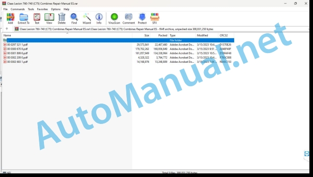
00 0297 321 1.pdf
00 0300 670 8.pdf
00 0301 899 6.pdf
00 0302 209 0.pdf
00 0302 683 1.pdf
00 0297 321 1.pdf:
LEXION 770 – 620
Introduction
General data
Manual validity
Using the manual
Texts and figures
Index with the structure of constructive groups
Search and find
Direction signs
Abbreviations
Technicalities
General repair instructions
Technical data
Indications for correct repair
Self-locking screws
Liquid screw insurance
Steel roller chains
connecting link
Tapered ring joints
Disassembly
Mounting
Head key joints
Disassembly
Mounting
Bearings with tension ring
Disassembly
Mounting
Bearings with tensioner sleeve
Disassembly
Mounting
Tension bushing
Disassembly
Mounting
Threadings with adjustment ring
Screw in
Non-tight joint with adjusting ring
Screw connections with sealing cone
Hydraulic hoses
Laying the hoses
Joint surface work
Replacement parts
Tightening torques
Tightening torques for normal metric threads
Tightening torques for metric fine threads
Tightening torques for hydraulic threads and air conditioning threads with sealing cone and O-ring DIN 3865
Tightening torques for hydraulic threads with adjusting ring DIN 3861
Tightening torques for threaded fittings of the SDS hydraulic system
Tightening torques for oscillating hydraulic threadings
Tightening torques for hollow screws DIN 7643
Tightening torques for threaded fittings of the SDE hydraulic system with adjustable direction
Tightening torques for brake line joints
Tightening torques for helical thread clamps
Tightening torques for spring-loaded helical thread clamps
Tire tightening torques
CCN Explanation
CCN (CLAAS Component Number)
General indications
Electrical regulations
Hydraulic regulations
CCN (CLAAS Component Number)
Security
General data
To especially take into account
Signaling of warning and alarm indications
General protection and safety rules at work
First aid
Risk of injury from hydraulic fluid
Leave the machine
Put the machine out of service
Raise the machine on supports
Adjustment and maintenance work
Welding work
03 Chassis
0315 Drive axle
Drive shaft
Technical instructions
shaft body
Technical instructions
Assembly instructions
axle connecting rod
Preparation for work
special tool
Technical instructions
Disassemble
wheel hub
Preparation for work
special tool
Technical instructions
Disassemble
differential gear
Preparation for work
special tool
Technical instructions
Disassemble
Adjust the axial play of the coupling nails
Preparation for work
special tool
Technical instructions
Disassemble
Gear shift control hydraulic cylinder (3063)
Technical instructions
Fork axle assembly instructions
Joint assembly instructions
0330 Rear drive steering axle
Identify drive axle
Drive steering axle
Technical instructions
Disassemble
shaft body
Preparation for work
special tool
Technical instructions
Disassemble
wheel hub
Preparation for work
special tool
Technical instructions
Completely remove the wheel hub
Completely install the wheel hub
Preparation for work
special tool
Technical instructions
Disassemble
Bearings
Technical instructions
Disassemble
Steering bars
Preparation for work
special tool
Technical instructions
Disassemble
Adjust tread and steering angle
Shaft drive valve block
Technical instructions
Disassemble
Hydraulic motor shaft drive (2003, 2004)
Preparation for work
special tool
Technical instructions
Disassemble
0330 Rear drive steering axle
Identify drive axle
Drive steering axle
special tool
Technical instructions
Disassemble
shaft body
Preparation for work
special tool
Technical instructions
Disassemble
Valid for the tire pressure adjustment system
Valid for the tire pressure adjustment system
wheel hub
Preparation for work
special tool
Technical instructions
Completely remove the wheel hub
Valid for the tire pressure adjustment system
Completely install the wheel hub
Valid for the tire pressure adjustment system
Preparation for work
special tool
Technical instructions
Disassemble
Bearings
Preparation for work
special tool
Technical instructions
Disassemble
Steering bars
Preparation for work
Technical instructions
Disassemble
Adjust tread and steering angle
Differential
Preparation for work
Technical instructions
Differential
Preparation for work
Technical instructions
Disassemble
Shaft drive valve block
Technical instructions
Assembly instructions
Double Pull Clutch Shift Cylinder (3002)
Technical instructions
Assembly instructions
Hydraulic Shaft Drive Motor (2068)
Preparation for work
Technical instructions
Disassemble
0365 Tire pressure regulating equipment
Tire pressure adjustment system
Preparation for work
special tool
Technical instructions
Disassemble
0370 Slope regulation
Hydraulic cylinder unevenness regulation
Preparation for work
Technical instructions
04 Brake
0405 Service brake
Braking mechanism
Technical instructions
Disassemble
Cylinder with elastic retainer
Preparation for work
Technical instructions
Disassemble
Basic adjustment of cylinder stroke
Check cylinder travel
Deactivate the brake
Activate the brake
05 Address
0505 Address
Hydraulic steering cylinder (3023)
Preparation for work
Technical instructions
Disassemble
Hydraulic steering cylinder (3023)
Technical instructions
Disassemble
0510 Automatic steering
AUTO PILOT steering angle sensor (B006)
Technical instructions
AUTO PILOT steering angle sensor (B006)
Technical instructions
00 0300 670 8.pdf:
Repair manual
Introduction
Information regarding the instruction manual
Manual validity
Information regarding this repair manual
Using the manual
Structuring with construction group structure
Search and find
Direction signs
General repair instructions
Technical instructions
Indications for correct repair
Self-locking screws
Liquid screw insurance
Steel roller chains
connecting link
Type E connecting link with spring
Type G connecting link with wire
S type connecting link with pins
Tapered ring joints
Disassembly
Mounting
Head key joints
Disassembly
Mounting
Bearings with tension ring
Disassembly
Mounting
Bearing with tensioner sleeve
Disassembly
Mounting
Tension bushing
Disassemble
Disassembly version A
Disassembly version B
Tension bushing version A
Tension bushing version B
Safety rings
Radial shaft seal rings
Hose clamps
Tightening torques
Hose orientation
Auxiliary assembly material
Assembly tools
Screw connections with adjustment ring
Screw connections with non-sealed adjusting ring
Screw connections with sealing cone
Hydraulic hoses
Laying of hoses
Diaphragm accumulator (pressure accumulator) based on factory regulations CLAAS CN 24 0403
Signaling
Operational means
Service and assembly
Changing the gas filling
special tool
Joint surface work
Replacement parts
Consumables
Welding work
ESD protection measures
special tool
ESD protection measures
Instructions for testing and repair
Tightening torques
Types of screw connections according to CLAAS CN 02 5000 factory regulations
Screwdriving case description
Tolerance class
Tightening prescription
Tightening torques for ISO metric thread
Tightening torques for metric fine threads
Tightening torques for hydraulic threadings with adjusting ring
Tightening torques for pipe threads with sealing cone connection and hydraulic connections with soft ring seal
Tightening torques for bulkhead fitting nuts, straight and angled
Tightening torques for SDS form B and E hydraulic threaded fittings
Tightening torques for threaded fittings of the SDS hydraulic system form F and sealing screw
Tightening torques for threaded fittings of the SDS hydraulic installation form H
Tightening torques for form E plug screws
Tightening torques for threaded fittings of the hydraulic installation form C, conical thread
Tightening torques for threaded fittings of the SDE hydraulic installation form F, adjustable direction
Tightening torques for SDE form H hydraulic threaded fittings, adjustable
Tightening torques for oscillating hydraulic threadings
Tightening torques for hollow screws (with copper gasket)
Tightening torques for brake pipe threading
Tightening torques for pipe supports with O-ring and union nuts
Tightening torques for threaded grub screws / diaphragms
Tightening torques for grub screws and special screws
Tightening torques for hydraulic parts
Tightening torques for hexagonal sealing nuts
Tightening torques for hose clamps
Assembly instructions
Helical thread tightening clamps
Helical thread tightening clamps with Belleville springs
Hose clamps with round bolt
CCN Explanation
CCN (CLAAS Component Number)
General indications
Electrical regulations
Hydraulic regulations
CCN (CLAAS Component Number)
Security
General information
Especially important
Danger symbols
Prescriptions to avoid accidents with personal injuries
General information
Check, adjustment and repair work
Engine operation
Lifted loads
Work on pipes and hoses
Work on the Common Rail system
Electrical installation work
Work in the hydraulic installation
Electric welding
paint jobs
Work with urea solution
Tips on how to avoid damage and premature wear
General indications
Limitation of liability
General indications
Immobilization and storage
Prescriptions to avoid damage to health and the environment
Prevention measures to protect against health and environmental damage
Disposal of consumables and auxiliary consumables
Instructions for working on the diesel engine
Protection against accidents
Cleaning
Assembly instructions
Engine check
Commissioning after an engine overhaul
First aid measures
01 Engine
0102 Complete component
Engine characteristic data
OM 470 LA
OM 471 LA
OM 473 LA
Engine Description
engine components
Actuators
Power-on sequence
turn the engine
special tool
Special tool with motor mounted
Turn the engine in assembled state
Turn the engine in disassembled state
Place the engine at the top dead center of the ignition
Place the engine at top dead center of the ignition: Disassemble
0105 Engine suspension
Hooking rings
Technical instructions
Hooking rings
Technical instructions
0110 Engine casing
Technical instructions
special tool
Disassemble
Front crankshaft gasket
Technical instructions
special tool
Disassemble
Install the cassette seal ring
Rear crankshaft gasket
Technical instructions
special tool
Disassemble
Housing cover
Technical instructions
Disassemble
control box
Technical instructions
Disassemble
Oil separator
Technical instructions
Disassemble
Oil separator
Technical instructions
Disassemble
Oil separator
Technical instructions
Disassemble
0115 Engine propulsion
Technical instructions
special tool
Disassemble
Measure the overhang
Check test pressure
Connecting rod
Technical instructions
special tool
Disassemble
Cylinder shirt
Technical instructions
special tool
Disassemble
Measure the overhang
Measure the cylinder bore
Crankshaft
Technical instructions
special tool
Disassemble the crankshaft
Check the crankshaft
Install the crankshaft
crankshaft main bearing
Technical instructions
special tool
Disassemble
Renew the main bearing of the calibrated bearing cover
Renew the main bearing of the calibrated bearing cover
Renew the crankshaft main bearing
Renew the crankshaft main bearing
Renew the main bearing of the calibrated bearing cover
Vibration damper
Technical instructions
special tool
Disassemble
flywheel
Technical instructions
special tool
Disassemble
0120 Cylinder head / valves / distributor wheel
cylinder head cover
Technical instructions
Disassemble
Intermediate frame
Technical instructions
Disassemble
camshaft housing
Technical instructions
special tool
Disassemble
Valid for: OM 470 LA
Valid for: OM 470 LA
Valid for: OM 470 LA
Valid for: OM 470 LA
Camshafts
Technical instructions
special tool
Disassemble
Technical instructions
special tool
Disassemble
Technical instructions
Preparation for work
special tool
Disassemble
Technical instructions
Preparation for work
special tool
Disassemble
Input rocker mechanism
Technical instructions
Disassemble
Outlet rocker mechanism
Technical instructions
special tool
Disassemble
Technical instructions
special tool
Disassemble
Check the valves
Adjust valve clearance
Engine brake valves
Technical instructions
special tool
Adjust engine brake valve clearance
Valve springs and valve stem seals
Technical instructions
special tool
Disassemble
toothed transmission
Technical instructions
special tool
Disassemble
toothed transmission
Technical instructions
special tool
Disassemble
toothed transmission
Technical instructions
special tool
Disassemble
0125 Fuel/injection system
High pressure pipes and rail
Technical instructions
special tool
Disassemble
Rail pressure limiting valve
Technical instructions
Disassemble
Injectors
Technical instructions
Preparation for work
special tool
Disassemble
Injector hose set
Technical instructions
Preparation for work
Disassemble
Protective cap
Technical instructions
special tool
Disassemble
High pressure fuel pump
Technical instructions
Preparation for work
special tool
Disassemble
OM470 LA, OM471 LA from 032691, OM473 LA
When the high pressure fuel pump sprocket (OM471 LA to 032690) is damaged
Remove the drive pinion
OM470 LA from 168338, OM471 LA from 168338, OM473 LA from 168338
OM470 LA from 168338, OM471 LA from 168338, OM473 LA from 168338
OM470 LA from 168338, OM471 LA from 168338, OM473 LA from 168338
Install the drive sprocket
OM470 LA from 168338, OM471 LA from 168338, OM473 LA from 168338
OM470 LA from 168338, OM471 LA from 168338, OM473 LA from 168338
OM470 LA from 168338, OM471 LA from 168338, OM473 LA from 168338
2 level valve
Technical instructions
Assembly instructions
fuel pump
Technical instructions
Preparation for work
special tool
Disassemble
Valid for: OM470 / 471 LA
Valid for: OM 470/471 LA
Pressure limiting valve
Technical instructions
Assembly instructions
Quantity regulating valve
Technical instructions
Preparation for work
Disassemble
Quantity regulating valve
Technical instructions
Preparation for work
Disassemble
Quantity regulating valve
Technical instructions
Preparation for work
Disassemble
fuel filter module
Technical instructions
Preparation for work
Mounting pins for mounting the fuel filter module
special tool
Disassemble
0130 Lubricating oil system
Lubricating oil system
Technical instructions
special tool
Oil injection nozzle
Technical instructions
Disassemble
Oil-coolant module
Technical instructions
Preparation for work
Disassemble
Oil radiator
Technical instructions
Assembly instructions
Oil radiator
Technical instructions
Assembly instructions
Oil pump
Technical instructions
Disassemble
Oil pump
Technical instructions
Disassemble
Oil pump
Technical instructions
Disassemble
oil thermostat
Technical instructions
special tool
Disassemble
0135 Cooling system
Cooling agent
Technical instructions
special tool
Fill out
Clean the coolant circuit
Coolant pump
Technical instructions
Preparation for work
Disassemble
Coolant thermostat
Technical instructions
Disassemble
0140 Exhaust gas system
Exhaust gas return radiator
Technical instructions
special tool
Disassemble
Exhaust gas return radiator
Technical instructions
special tool
Disassemble
Exhaust gas return radiator
Technical instructions
special tool
Disassemble
Exhaust gas return radiator support
Technical instructions
Preparation for work
Remove the exhaust gas return radiator support
Install the exhaust gas return radiator support
Exhaust gas return actuator
Technical instructions
Disassemble
Exhaust gas return actuator
Technical instructions
special tool
Disassemble
Exhaust gas return valve
Technical instructions
Disassemble
Differential pressure sensor
Technical instructions
exhaust gas elbow
Technical instructions
Preparation for work
Disassemble
exhaust gas elbow
Technical instructions
Preparation for work
Disassemble
exhaust gas elbow
Technical instructions
Preparation for work
Disassemble
Exhaust gas turbocharger
Technical instructions
Preparation for work
Disassemble
Exhaust gas turbocharger
Technical instructions
Preparation for work
Disassemble
Exhaust gas turbocharger
Technical instructions
Preparation for work
Disassemble
TURBO-COMPOUND turbine
Technical instructions
Preparation for work
Disassemble
TURBO-COMPOUND gear
Technical instructions
Preparation for work
Disassemble
0145 Air suction
Air intake housing
Technical instructions
Disassemble
Air intake housing
Technical instructions
Disassemble
0150 Engine coupled parts
Starting motor
Technical instructions
Disassemble
Generator
Technical instructions
special tool
Disassemble the generator
Assemble the generator
Resonance vessel
Technical instructions
Assembly instructions
Resonance vessel
Technical instructions
Assembly instructions
pressure air compressor
Technical instructions
Preparation for work
special tool
Disassemble
Remove the drive pinion
Install the drive sprocket
pressure air compressor
Technical instructions
Preparation for work
special tool
Disassemble
Remove the drive pinion
Install the drive sprocket
0155 Engine adjustment
control device
Technical instructions
Disassemble
Only when the control unit is renewed
OM470 LA and OM471 LA with front air intake
0165 Exhaust gas aftertreatment
Exhaust gas aftertreatment system
Technical instructions
Preparation for work
special tool
Check the urea solution (purity)
Control the urea solution (density)
Diesel particulate filter exhaust aftertreatment
Technical instructions
Disassemble
Install the DPF
Mount the profile clamp
Assemble the flat band clamp
Install service cover
urea heating valve
Technical instructions
Preparation for work
special tool
Disassemble
urea pump
Technical instructions
Preparation for work
special tool
Disassemble the urea pump
Assemble the urea pump
Remove the filter from the inlet fitting
Install the inlet fitting filter
Remove the pressure limiting valve
Install the pressure relief valve
Remove the antifreeze element
Install the antifreeze element
Urea Dosing Unit (A089/A67-MB)
Technical instructions
Preparation for work
special tool
Separate the hose (flexible hoses only)
Disassemble the dosing unit
Assemble the dosing unit
Disassemble the filter
Install the filter
0190 Accessories
motor insulation
Technical instructions
Preparation for work
Disassemble
00 0302 209 0.pdf:
LEXION 780-620
Introduction
General information
Using the manual
Texts and figures
Division with construction group structure
Search and find
Direction signs
Abbreviations
Technicalities
Manual validity
Security
General information
Especially important
Danger symbols
General safety measures and accident prevention rules
Safety measures and accident prevention in combine harvesters
First aid measures
Leave the machine
Adjustment and maintenance work
Risk of injury from hydraulic fluid
Battery separator switch
Raise the machine on supports
Put the machine out of service
04 Brake
0415 Parking brake
Parking break
Technical instructions
Preparation for work
special tool
Remove the brake shims
Install the brake shims
Remove the brake disc
Install the brake disc
Remove the sliding caliper
Install the sliding caliper
Check the thickness of the remaining brake shim brake pad and the piston stroke.
Bleed the parking brake
Adjust the parking brake
00 0302 683 1.pdf:
LEXION 760LEXION 750LEXION 740
Manual validity
Manual validity
General security measures
To especially take into account
Signage of warning and danger indications
Security
01 Engine
0165 Exhaust gas aftertreatment
Repair kit supply set 00 2597 549 0
Assembly repair kit 00 2597 549 0
Repair kit supply set 00 2597 545 0
Assembly repair kit 00 2597 545 0
Repair kit supply set 00 2597 565 0
Assembly repair kit 00 2597 565 0
Repair kit supply set 00 2597 562 0
Assembly repair kit 00 2597 562 0
John Deere Repair Technical Manual PDF
John Deere Application List Component Technical Manual CTM106819 24AUG20
John Deere Repair Technical Manual PDF
John Deere Repair Technical Manual PDF
John Deere Repair Technical Manual PDF
John Deere Repair Technical Manual PDF
John Deere Repair Technical Manual PDF
John Deere Repair Technical Manual PDF
John Deere 16, 18, 20 and 24HP Onan Engines Component Technical Manual CTM2 (19APR90)
John Deere Repair Technical Manual PDF
John Deere Parts Catalog PDF
John Deere Tractors 7500 Parts Catalog CPCQ26568 30 Jan 02 Portuguese

