Claas Liner 1650 (G00) Swathers Operator Manual ES
$50.00
- Model: Liner 1650 (G00) Swathers
- Type Of Manual: Operator Manual
- Language: ES
- Format: PDF(s)
- Size: 15.0 MB
File List:
00 0291 540 3.pdf
00 0291 540 3.pdf:
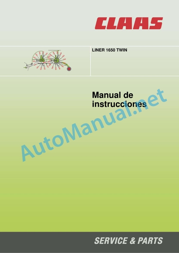
LINER 1650 TWIN
1 Regarding this instruction manual
1.1 Information regarding the instruction manual
1.1.1 General instructions
1.1.2 Validity of the manual
1.1.3 Use of the manual
Direction signs
1.1.4 Technical instructions
1.1.5 Symbols and indications
2 Security
2.1 Safety instructions
2.1.1 To take special account
2.1.2 Qualification of piloting and maintenance personnel
2.1.3 Proper machine application
2.1.4 Logically foreseeable inappropriate application
2.1.5 Protection and safety standards at work
2.1.6 First aid measures
2.1.7 Risk of injury from hydraulic fluid
2.2 Safety instructions on the machine
2.2.1 Warning symbols
2.2.2 Position of warning symbols
3 Machine Description
3.1 Summary and operation
3.1.1 Summary LINER 1650 TWIN
3.1.2 Machine operation
3.2 Optional machine equipment
3.2.1 Additional swath canvas
3.2.2 Rear tandem axles
3.2.3 Spare wheel 16×6.5-8
3.2.4 Wheel weights
3.2.5 Hydraulic connection parts 1 components
3.2.6 Insertable fork 8 components
3.2.7 Lighting adapter for USA
3.2.8 SMV Triangle
3.3 Identification plates and vehicle identification number
3.3.1 Spare parts and technical queries
3.3.2 Identification plate position
3.3.3 Identification number position
3.3.4 Machine identification plate explanation
3.4 Machine information
3.4.1 Adhesive
4 Control and display instruments
4.1 Windrowing rotor
4.1.1 Crank
4.1.2 Raking height scale
4.1.3 Pull rope
4.2 Hydraulic system flexible tubing
4.2.1 Stopcock
4.3 Support leg
4.3.1 Button
5 Technical data
5.1 LINER 1650 TWIN
5.1.1 Measurements
5.1.2 Weights
5.1.3 Requirements for the tractor
5.1.4 Model
5.1.5 Tire air pressure
5.1.6 Acoustic intensity level
5.1.7 Lubricants
6 Preparation of the machine
6.1 Adapt the machine
6.1.1 Cardan shaft – check the length
6.1.2 Cardan shaft – adapt the length
6.1.3 Mount the cardan shaft to the machine
6.1.4 Install wheel weights*
6.2 Hooking up the machine
6.2.1 Attach the hitch bracket
6.2.2 Adjust the hitch bracket
6.2.3 Assemble the cardan shaft
6.2.4 Connect the hydraulic pipe
6.2.5 Attach the pull rope
6.2.6 Plug in the cables for lighting
6.2.7 Save shims
6.3 Unhook the machine
6.3.1 Put the shims underneath
6.3.2 Unplug the lighting cables
6.3.3 Unhook the pull rope
6.3.4 Disconnect the hydraulic pipe
6.3.5 Dismantle the cardan shaft
6.3.6 Unhook the coupling bracket
6.4 Prepare for road traffic
6.4.1 General security measures
6.4.2 Folding the protection bracket
6.4.3 Remove the tine arms
6.4.4 Push the swath cloth inwards
6.4.5 Fix the swath canvas in transport position
6.4.6 Remove the additional swath cloth*
6.4.7 Fold the machine into transport position
6.4.8 Close the stopcock
6.4.9 Insert the protective bars
6.5 Prepare the working position
6.5.1 Remove the protective bars
6.5.2 Open the stopcock
6.5.3 Deploy the machine to the working position
6.5.4 Assemble the tine arms
6.5.5 Deploy the swath canvas to the working position
6.5.6 Insert the additional swath cloth*
6.5.7 Deploy the protective stirrups
6.6 Machine loading
6.6.1 Lift the machine
7 Management
7.1 General security measures
7.1.1 Take into account before handling
7.2 Driving on the road
7.2.1 Driving on public roads
7.3 Settings for use at work
7.3.1 General instructions
7.3.2 Adjust the swath rotor
7.3.3 Adjust the raking height
7.3.4 Adjusting the row former
7.3.5 Adjusting the second swath curtain*
7.3.6 Adjust position for plot ends
7.3.7 Adjust the sequential hydraulic control
7.3.8 Adjust the steering stop
7.4 Use at work
7.4.1 Take into account during field trips
7.4.2 Take into account the angle of rotation
7.4.3 Adjust individual row placement
Adjust rotor overlap
7.4.4 Adjust the placement of two rows
7.4.5 Straw rows
Additional swath cover*
7.4.6 Connect the power take-off
Optimal power take-off speed
7.4.7 Raise the swath rotors to the end-of-field position
Sequential hydraulic control
8 Incident and solution
8.1 Incident and solution
8.1.1 Take into account to eliminate faults
8.1.2 Hydraulic installation
8.1.3 Feeler wheels
9 Maintenance
9.1 Maintenance instructions
9.1.1 General warning instructions for maintenance
9.1.2 Electrical installation
9.1.3 Protection devices
9.1.4 Spare parts
9.1.5 Imbalance
9.1.6 Pressurized air and water
9.1.7 Wheels / tires
9.1.8 Prevention against burns
9.1.9 Oil
9.1.10 Prevention against fires and explosions
9.1.11 Pipes, tubes and hoses
9.2 Summary of maintenance intervals
9.2.1 Management of maintenance intervals
9.2.2 Before starting the harvest
9.2.3 After the first 10 hours of service
9.2.4 After the first 50 hours of service
9.2.5 Every 8th of service or daily
9.2.6 Every 20 hours of service
9.2.7 Every 50 hours of service
9.2.8 Every 100 hours of service
9.2.9 Every 250 hours of service
9.2.10 Every 500 hours of service or annually
9.2.11 If necessary
9.2.12 After harvest
9.3 General maintenance work
9.3.1 Clean the machine
9.3.2 Maintain the machine
9.3.3 Prevent freeze damage
9.3.4 Fixing material
9.4 Gear maintenance work
9.4.1 Check the tightness of the gear
9.4.2 Main gear, check oil level
9.4.3 Main gear, change oil
9.4.4 Main gear, retighten the screws
9.4.5 Bevel gear, check oil level
9.4.6 Bevel gear, change oil
9.4.7 Bevel gear, retighten the screws
9.4.8 Check the swath gear oil level
9.4.9 Change the swath gear oil
9.4.10 Windrower gear, retighten the screws
9.5 Maintenance work on the clutch
9.5.1 Adjust the lockup clutch
9.6 Cardan shaft maintenance work
9.6.1 Maintain the cardan shafts
9.6.2 Retighten the cardan shaft nuts
9.7 Chassis maintenance work
9.7.1 Check tire pressure
9.7.2 Change wheel
9.7.3 Change feeler wheel
Rear tandem axle*
9.7.4 Check/adjust tread
Adjust the steering bar
9.7.5 Check/adjust toe-in
9.8 Hydraulic installation maintenance work
9.8.1 Carry out maintenance on the hydraulic installation
9.8.2 Perform maintenance on hydraulic hoses
9.9 Maintenance work on the chassis
9.9.1 Check the hitch bracket
9.9.2 Check the fixation of the chassis
9.10 Windrower rotor maintenance work
9.10.1 Check the fixation of the swath gear
9.10.2 Check the engagement of the swath rotors
9.10.3 Adjust discharge parts
9.10.4 Check the tine holder supports
9.10.5 Check the elastic tines
9.11 Greasing scheme
9.11.1 Grease the lubrication points every 20 hours
9.11.2 Grease the lubrication points every 50 hours
9.11.3 Grease the grease points every 100 hours
9.11.4 Grease the lubrication points every 250 hours
10 Decommissioning and waste disposal
10.1 General data
10.1.1 End of operational life and waste disposal
11 EU declaration of conformity
11.1 EC declaration of conformity
12 Technical dictionary and abbreviations
12.1 Terms and explanations
12.1.1 Technical vocabulary
12.1.2 Abbreviations
John Deere Repair Technical Manual PDF
John Deere Repair Technical Manual PDF
John Deere Repair Technical Manual PDF
John Deere Repair Technical Manual PDF
John Deere Repair Technical Manual PDF
John Deere 18-Speed PST Repair Manual Component Technical Manual CTM168 10DEC07
John Deere Repair Technical Manual PDF
John Deere Diesel Engines POWERTECH 2.9 L Component Technical Manual CTM126 Spanish
John Deere Repair Technical Manual PDF
John Deere 16, 18, 20 and 24HP Onan Engines Component Technical Manual CTM2 (19APR90)
John Deere Repair Technical Manual PDF
John Deere PowerTech M 10.5 L and 12.5 L Diesel Engines COMPONENT TECHNICAL MANUAL CTM100 10MAY11


