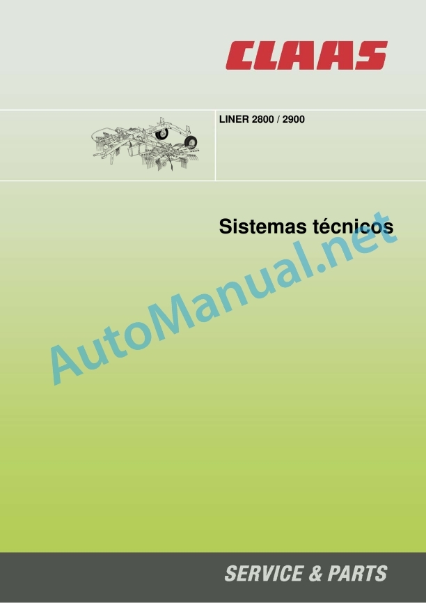
Claas Liner 2900 (988) Swathers Technical System ES
$150.00
- Model: Liner 2900 (988) Swathers
- Type Of Manual: Technical System
- Language: ES
- Format: PDF(s)
- Size: 1.7 MB
File List:
00 0291 641 0.pdf
00 0291 641 0.pdf:
CCN Explanation
CCN (CLAAS Component Number)
General indications
Regulations for electrical installation
Regulations for hydraulic installation
CCN (CLAAS Component Number)
CCN Index
Introduction
09 Hydraulic
0980 Hydraulic connection diagram
Hydraulic connection diagrams LINER 2800 / 2900 without individual lifting of the rotors
Hydraulic connection diagram LINER 2800 / 2900 with individual manual lifting of each rotor
Hydraulic connection diagram LINER 2800 / 2900 with Communicator
10 Install. electrical/electronic
1012 Modules / sensors
Windrower module (A129), LINER 2800 / 2900
Plug pin assignment X1
Plug pin assignment X2
1080 Electronic connection diagram
Electrical connection diagram LINER 2800 / 2900 with Communicator
Electrical connection diagram LINER 2800 / 2900 with CLAAS Standard Terminal (CST)
Location of components
Hydraulic
3000 Hydraulic Cylinders
4000 Restrictors/chokes
6000 Valves – mechanically operated
7000 Valves – hydraulically operated
8000 Clutches / connections
Electrical installation
To Terminal/modules
and electromagnetic coils
John Deere Repair Technical Manual PDF
John Deere Repair Technical Manual PDF
John Deere Transmission Control Unit Component Technical Manual CTM157 15JUL05
John Deere Repair Technical Manual PDF
John Deere Application List Component Technical Manual CTM106819 24AUG20
John Deere Repair Technical Manual PDF
John Deere Repair Technical Manual PDF
John Deere Parts Catalog PDF
John Deere Harvesters 8500 and 8700 Parts Catalog CPCQ24910 Spanish
John Deere Repair Technical Manual PDF
John Deere Repair Technical Manual PDF


