Claas Markant 65 (041) Balers Technical System EN
$150.00
- Model: Markant 65 (041) Balers
- Type Of Manual: Technical System
- Language: EN
- Format: PDF(s)
- Size: 18.7 MB
File List:
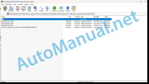
00 0185 371 5.pdf
00 0302 343 1.pdf
00 0302 565 2.pdf
CHP-numbers for connectors CLAAS HARNESS PARTS.pdf
00 0302 343 1.pdf:
PROFI CAM 3
Table of contents
General information
Marking of warnings and hazard prevention notes
First-aid measures
CCN explanation
CCN (CLAAS Component Number)
Electric system standard
Hydraulic system standard
CCN (CLAAS Component Number)
10 Electrical / Electronic equipment
1030 Board computer / Indicators
Camera system
Description of function
1097 Testing / Measuring / Adjusting
Testing / measuring / adjusting the PROFI CAM
Checking the fuse in the video channel select box (C102)
Testing the video camera connector (C055)
1098 Fault / remedy
Fault / remedy PROFI CAM
The video monitor (C101) shows no image or cannot be switched on (indicator light fails to light up)
Video monitor (C102) displays a blue image either permanently or temporarily
The video monitor image is blurred
Replacing the fuse in the video channel select box (C102)
Connection and connecting cable with video camera (C055)
00 0302 565 2.pdf:
Sensor system
Table of contents
CCN explanation
CCN (CLAAS Component Number)
Electric system standard
Hydraulic system standard
CCN (CLAAS Component Number)
Introduction
Safety rules
Safety and hazard information
10 Electrical / Electronic equipment
1097 Testing / Measuring / Adjusting
Test report of the angle sensor (0011780.x)
Application of test report
Required tools
Test report of the angle sensor (0011780.x)
Testing / Measuring / Adjusting of angle sensor (0011780.x)
1. Reason for test
2. Mechanical test of angle sensor
3. Electric test with CDS
4. Electric test with multimeter
5. Mechanical test of connecting cable
Completing the machine
Test report of position and speed sensors
Application of test report
Required tools
Sensor variants
Part numbers of speed sensors
Part number of position sensor
Test report of position and speed sensors
Testing / measuring / adjusting of position and speed sensors
1. Reason for test
2. Mechanical test
3. Electric test with CDS
4a. Installation dimensions
Check of installation dimension
Installation dimensions of gearbox speed sensor (0011 799.x) and cam speed sensor (0011 810.x)
Installation dimension of position sensor (0011 815.x)
4b. Installation position
Centring of sensor
Metal-free zone
5. Electric test with multimeter
Voltage measurement
Direction of rotation and speed sensor (0011 605.x)
Measured values table
6. Mechanical test of connecting cable
Completing the machine
Test report of the urea sensor (00 0773 207 x)
Application of test report
Required tools
Parts number of the urea sensor
Test report of the urea sensor
Testing / measuring / adjusting urea sensor
1. Reason for test
2. Mechanical test
3. Mechanical test of connecting cable
4. Electric test with multimeter
5. Component test with the CDS
CHP-numbers for connectors CLAAS HARNESS PARTS.pdf:
CLAAS HARNESS PARTS
Table of contents
10 Electrical / Electronic equipment
1081 Overview of connectors
CLAAS HARNESS PARTS (CHP)
John Deere Repair Technical Manual PDF
John Deere Repair Technical Manual PDF
John Deere DF Series 150 and 250 Transmissions (ANALOG) Component Technical Manual CTM147 05JUN98
John Deere Repair Technical Manual PDF
John Deere Repair Technical Manual PDF
John Deere Repair Technical Manual PDF
John Deere Repair Technical Manual PDF
John Deere Repair Technical Manual PDF
John Deere Repair Technical Manual PDF

