Claas Nexos 230-220 Fb (A29) Tractors Technical System ES
$150.00
- Model: Nexos 230-220 Fb (A29) Tractors
- Type Of Manual: Technical System
- Language: ES
- Format: PDF(s)
- Size: 115 MB
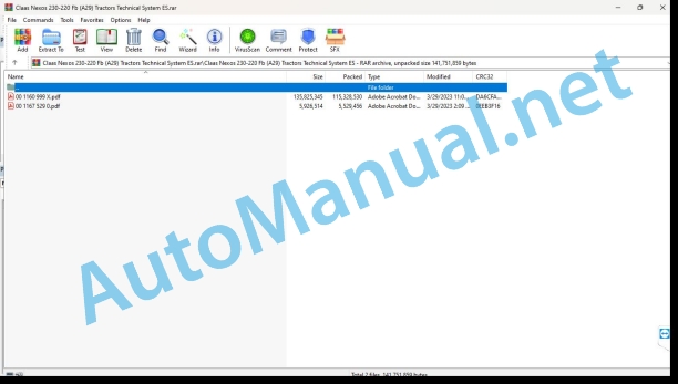
File List:
00 1160 999 X.pdf
00 1167 529 0.pdf
00 1160 999 X.pdf:
Technical systems
CCN Explanation
CCN (CLAAS Component Number)
General indications
Electrical regulations
Hydraulic regulations
CCN (CLAAS Component Number)
Introduction
Manual validity
Validity of this diagnostic manual
01 Engine
0125 Fuel/injection system
Fuel supply circuit (F5C)
Measurement value table
Function Description
Hydraulic diagram of the fuel supply circuit
Fuel injection circuit (F5C)
Function Description
Description of operation
Load-dependent flow adaptation device (LDA)
Hydraulic diagram of the fuel injection circuit
fuel return circuit
Electric scheme
0130 Lubricating oil system
Engine lubrication circuit (F5C)
Measurement value table
Function Description
Hydraulic diagram of the engine lubrication circuit
0135 Cooling system
Engine cooling circuit (F5C)
Measurement value table
Function Description
Engine thermostat control
0140 Exhaust gas system
Engine exhaust circuit (F5C)
Function Description
0145 Air suction
Engine air intake circuit (F5C)
Measurement value table
Function Description
0150 Engine coupled parts
Engine start (F5C)
Measurement value table
Function Description
01 Engine
0125 Fuel/injection system
Fuel supply circuit (NEF)
Measurement value table
Function Description
Hydraulic diagram of the fuel supply circuit
Fuel injection circuit (NEF)
Function Description
Hydraulic diagram of the fuel injection circuit
injection pump
fuel return circuit
engine wiring
0130 Lubricating oil system
Engine lubrication circuit (NEF)
Measurement value table
Function Description
Hydraulic diagram of the engine lubrication circuit
0135 Cooling system
Engine cooling circuit (NEF)
Measurement value table
Function Description
Engine thermostat control
0140 Exhaust gas system
Engine exhaust circuit (NEF)
Function Description
0145 Air suction
Engine air intake circuit (NEF)
Measurement value table
Function Description
0150 Engine coupled parts
Engine start (NEF)
02 Gears / clutch / cardan shaft
0202 Complete component
Transmission kinematics
Transmission 12 + 12
24+24 transmission with mechanical duplicator
24+24 transmission with hydraulic doubler
24+12 transmission with hydraulic shuttle and mechanical rear PTO clutch
24+12 transmission with hydraulic shuttle and hydraulic rear PTO clutch
Preponderance
0220 Mechanical investment
mechanical inverter
0222 Hydraulic inversion
REVERTSHIFT Hydraulic Inverter
Measurement value table
Function Description
Clutch pedal operation and adjustment
0230 Mechanical gear
Mechanical duplicator, speeds and mechanical ranges
0234 Load Switching Gear
«Twinshift» hydraulic duplicator
0242 Differential
Rear differential lock
Measurement value table
Operating law
0252 Electrohydraulic drive of the front axle
Traction on the four wheels
Measurement value table
Operating law
0297 Check / measure / adjust
Transmission Calibration
“TCU A057” Transmission Control Module Interface Menu
Tractor model configuration
Clutch Pedal Calibration Menu
Clutch pressure sensor calibration menu
Lever progressiveness adjustment menu
Pedal progression adjustment menu
Hydraulic duplicator progressivity adjustment menu
“Limp Home” function activation menu
Help menu for diagnosis of REVERSHIFT, duplicator control and clutch pedal
Transmission Calibration
“TCU A057” Transmission Control Module Interface Menu
Tractor model configurationPedal Calibration Menu
Clutch pressure sensor calibration menu
Lever pradjustment menu
Pedal progression adjustment menu
Hydraulic duplicator progressivity adjustment menu
“Limp Home” function activation menu
Help menu for diagnosis of REVERSHIFT, duplicator control and clutch pedal
Checking the supply pressure of the hydraulic shuttle clutches
Checking Differential Supply Pressure
Checking the four-wheel drive power take-off supply pressure
03 Chassis
steering axis
04 Brake
0405 Service brake
Service brake
0425 Hydraulic Trailer Brake
Hydraulic Trailer Brake
Measurement value table
05 Address
0505 Address
Main address
Checking the steering pressure relief valve «7026»
Control of the opening pressure of the anti-shock valves «7153»
06 Lifting device
0605 Rear linkage
Mechanical rear hydraulic lift
neutral position
Lowering position
Rise position
Checking the rear linkage she
Hydraulic compensator and lift support
Kinematic scheme
Hydraulic diagram
cal architecture
Status of the solenoid valves
0615 Front loader
Front loader hydraulic connections
Connecting the front loader to the tractor hydraulic distributors
Connecting the front loader to the Mach hydraulic distributors
Mach hydraulic connection
Electrical connection for functions 3 and 4
08 Drives
0802 Rear PTO
rear power take off
Operating law
Checking the power take-off brake supply pressure
Checking the power take-off clutch pressure
electrical part
hydraulic part
Operating law
09 Hydraulics
0920 Valves
Hydraulic circuit with two pumps and two distributors
Hydraulic circuit with two pumps and three distributors
Hydraulic circuit with two pumps and three distributors with flow regulator in the middle
Hydraulic circuit with two pumps and four distributors with flow regulator in the middle
Hydraulic circuit of three pumps and three distributors with flow regulator in the middle
Hydraulic circuit with three pumps and four distributors with flow regulator in the middle
Hydraulic circuit of three pumps and electrohydraulic distributors
Rear mechanical distributor
Three-position mechanical distributor
Four-position mechanical distributor
Intermediate plate
Bottom plate
Top plate
Auxiliary electrohydraulic distributor
Hydraulic architecture
Function Description
Hydraulic system circuit breaker solenoid valve
entrance plate
Closing plate
Distributors position
Distributor in neutral position
Distributor in flow position
0980 Hydraulic connection diagram
Mechanical transmission hydraulic circuit (12 x 12)
Mechanical transmission hydraulic circuit (24 x 24) with “Twinshift” hydraulic duplicator
Mechanical transmission hydraulic circuit (24 x 12) “Revershift”
10 Install. electrical/electronic
1010 Central al system
Engine compartment fuse box
Preheat fuse
Electronic elevator fuse and relay
main fuse
Main fuse box
Right pillar fuse box
Left pillar fuse box
Fuse box under the instrument panel
1012 Modules / sensors
Module overview
A057 Transmission control module
A060 Hydraulic system control module
A101 Control panel module
A117, A118, A119, A120 Distributors 1, 2, 3, 4
A147 Rear linkage control panel
1015 Cable sets
Wiring list
W01 – Main wiring without electrical distributor
W01 – Main wiring with electrical distributors
W02 – Motor wiring
W03 – Transmission wiring
W04 – Ventilation and air conditioning wiring
W05 – Lighting wiring
W06 – Pneumatic braking wiring
W08 – Air conditioning compressor wiring
W09 – Hitch compensator main wiring
W09-2 – Hitch Compensator Secondary Wiring
W11 – Rear linkage power wiring
W11-2 – Rear linkage secondary wiring
W11-3 – Rear linkage main wiring
W11-4 – Rear linkage rear control wiring
W12 – Secondary wiring of electrical distributors
W13 – Main wiring of electrical distributors
1080 Electrical connection diagram
SCM01 Work lighting
SCM01-01 Front work lights on top of cab
Component List
SCM02 Road signs
SCM02-01 Position lights
Component List
SCM02-02 Low beams – High beams
Component List
SCM02-03 Flashing – Emergency lights
Component List
SCM02-04 Brake lights
Component List
SCM02-05 Rotating flashing light
Component List
SCM02-06 Acoustic warning
Component List
SCM03 Ventilation and air conditioning
SCM03-01 Ventilation and air conditioning (Elios)
Component List
SCM03-02 Ventilation and air conditioning (Nexos)
Component List
SCM04 Elevator – PTO (before 2009)
SCM04-01 Rear linkage and electro-hydraulic distributors (before 2009)
Component List
SCM04-02 Rear PTO (before 2009 with mechanical shuttle)
Component List
SCM04-02 Rear PTO (before 2009 with REVERSHIFT)
Component List
SCM04-03 Front PTO (before 2009)
Component List
SCM04-04 Hydraulic elevator compensator (before 2009)
Component List
SCM04-05 Hydraulic System Module (before 2009)
Component List
SCM04-06 Elevator Module (before 2009)
Component List
SCM04 Elevator – PTO (with mechanical inverter)
SCM04-01 Rear linkage and electrohydraulic distributors (with mechanical shuttle)
Component List
SCM04-02 Rear power take-off (with mechanical shuttle)
Component List
SCM04-03 Front power take-off (with mechanical shuttle)
Component List
SCM04-04 Hydraulic elevator compensator (with mechanical reverser)
Component List
SCM04-05 Hydraulic system module (with mechanical shuttle)
Component List
SCM04-06 Elevator module (with mechanical inverter)
Component List
SCM04 Elevator – PTO (REVERSHIFT)
SCM04-01 Rear linkage and electrohydraulic distributors (REVERSHIFT)
Component List
SCM04-02 Rear PTO (REVERSHIFT)
Component List
SCM04-03 Front PTO (REVERSHIFT)
Component List
SCM04-04 Hydraulic elevator compensator (REVERSHIFT)
Component List
SCM04-05 Hydraulic System Module (REVERSHIFT)
Component List
SCM04-06 Elevator Module (REVERSHIFT)
Component List
SCM05 Starting and charging circuit (before 2009)
SCM05 Starting and charging circuit (before 2009)
Component List
SCM05 Starting and charging circuit (REVERSHIFT)
SCM05 Starting and charging circuit (REVERSHIFT)
Component List
SCM05 Starting and charging circuit (REVERSHIFT)
SCM05 Starting and charging circuit (REVERSHIFT)
Component List
SCM06 Transmission (before 2009)
SCM06-01 Transmission (before 2009)
Component List
SCM06-02 Transmission Module (before 2009)
Component List
SCM06-03 Electro-hydraulic duplicator and mechanical reverser (before 2009)
Component List
SCM06-04 Four-wheel drive (before 2009)
Component List
SCM06-05 Differential lock (before 2009)
Component List
SCM06 Transmission (with mechanical shuttle)
SCM06-03 Electro-hydraulic duplicator and mechanical shuttle (with mechanical shuttle)
Component List
SCM06-04 Four-wheel drive (with mechanical shuttle)
Component List
SCM06-05 Differential lock (with mechanical reverser)
Component List
SCM06-06 Four-wheel drive and parking brake (with mechanical shuttle)
Component List
SCM06 Transmission (REVERSHIFT)
SCM06-01 Transmission (REVERSHIFT)
Component List
SCM06-02 Transmission Module (REVERSHIFT)
Component List
SCM06-03 Electrohydraulic duplicator and mechanical inverter (REVERSHIFT)
Component List
SCM06-04 Four Wheel Drive (REVERSHIFT)
Component List
SCM06-05 Differential lock (REVERSHIFT)
Component List
SCM06-06 Four Wheel Drive and Parking Brake (REVERSHIFT)
Component List
SCM07 Accessories
SCM08 Windshield wiper, windshield washer
SCM08-01 Windshield wiper, washer (front)
Component List
SCM08-01 Windshield wiper, washer (rear)
Component List
SCM10 CAN Network (before 2009)
SCM10 CAN network (with mechanical inverter)
SCM10 Network CAN (REVERSHIFT)
SCM11 Power
SCM12 Connection of the tractor to the implements
SCM13 Pneumatic braking system
SCM18 Engine (before 2009)
SCM18 Motor (with mechanical inverter)
SCM18 Engine (before 2009)
SCM19 Instrument panel (before 2009)
SCM19 Instrument panel (with mechanical inverter)
SCM19 Instrument panel (REVERSHIFT)
1085 Networks
CAN bus network architecture, mechanical inverter version
Location of CAN bus resistors
CAN bus network architecture, hydraulic inverter version
CAN bus network
Location of CAN bus resistors
92 Diagnosis
Presentation of error codes
Introduction
Viewing error codes
9210 Machine Error Codes
Description of the error code list
Error code
Emitter module
Denomination
Code list
Location of components
Hydraulic installation
1000 Oil tank. Oil filter. oil cooler
2000 Bomb. Engine
3000 Hydraulic Cylinders
5000 Pressure accumulators
6000 Valves (mechanical control)
7000 Hydraulic Control Valves
Electrical installation
To Terminal. Modules
B Sensors
C Electrical, electronic devices
G Voltage source
and lighting
H Signaling device. Light indicator
M Motor (electric)
R Potentiometers. Resistors
S Switches. Switches (control in cabin)
U Switches. External controls
V Electronic components
X Connections
and electromagnetic coil
Z Actual value switches
00 1167 529 0.pdf:
ELIOS 240-200NEXOS 250-210 VL-L-VE-FB
90 Others
9090 Diagnostic
Gearbox diagnostic protocol
Checking the oil level of the hydraulic circuit
Diagnostic protocol development
Checking the oil level in the REVERSHIFT crankcase
Checking the pressure in the REVERSHIFT crankcase
Checking the REVERSHIFT lubrication flow rates
Automatic Transmission Advance Test
Checking for oil leaks in the REVERSHIFT crankcase
Checking the REVERSHIFT pressure
John Deere Repair Technical Manual PDF
John Deere Repair Technical Manual PDF
John Deere Repair Technical Manual PDF
John Deere Repair Technical Manual PDF
John Deere Repair Technical Manual PDF
John Deere DF Series 150 and 250 Transmissions (ANALOG) Component Technical Manual CTM147 05JUN98
John Deere Parts Catalog PDF
John Deere Tractors 6300, 6500, and 6600 Parts Catalog CQ26564 (29SET05) Portuguese
John Deere Repair Technical Manual PDF
John Deere Repair Technical Manual PDF
John Deere Diesel Engines POWERTECH 2.9 L Component Technical Manual CTM126 Spanish
John Deere Repair Technical Manual PDF
John Deere Repair Technical Manual PDF


