Claas Nexos 260-210 L Stage V (A67) Tractors Technical System ES
$300.00
- Model: Nexos 260-210 L Stage V (A67) Tractors
- Type Of Manual: Technical System
- Language: ES
- Format: PDF(s)
- Size: 137 MB
File List:
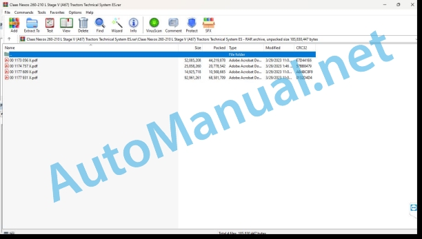
00 1173 056 X.pdf
00 1174 757 X.pdf
00 1177 609 X.pdf
00 1177 931 X.pdf
00 1174 757 X.pdf:
Technical systems
CCN Explanation
CCN (CLAAS Component Number)
General indications
Electrical regulations
Hydraulic regulations
CCN (CLAAS Component Number)
Introduction
Manual validity
Validity of this diagnostic manual
01 Engine
0125 Fuel/injection system
fuel supply circuit
Measurement value table
Function Description
Hydraulic diagram of the fuel supply circuit
Fuel supply pressure control
Checking fuel pressures
fuel injection circuit
Measurement value table
Function Description
Hydraulic diagram of the fuel injection circuit
fuel return circuit
engine wiring
0130 Lubricating oil system
Engine lubrication circuit
Measurement value table
Function Description
Hydraulic diagram of the engine lubrication circuit
Engine lubrication pressure control
0135 Cooling system
Engine cooling circuit
Measurement value table
Function Description
Engine thermostat control
0140 Exhaust gas system
Engine exhaust circuit
Measurement value table
Function Description
Exhaust gas and recycled exhaust gas circuit diagram
Checking the “EGR” cooler
0145 Air suction
Engine air intake circuit
Measurement value table
Function Description
0150 Engine coupled parts
Engine start
Measurement value table
Function Description
0155 Engine adjustment
Engine speed setpoint
Measurement value table
Function Description
Calibration of the accelerator pedal sensor «B153» and the engine speed adjustment sensor «B154»
Calibration of the «CLAAS Power Management» sensors
0165 Exhaust gas aftertreatment
Engine aftertreaem
Function Description
Principle diagram of the urea circuit
AdBxhaust gas circulation
Engine power reduction
Automatic regeneration
Regeneration when stopped or in service
02 Gears / clutch / cardan shaft
0202 Complete component
Transmission kinematics
12 + 12 transmission, with mechanical shuttle and four-wheel drive (L)
12 + 12 transmission, with mechanical shuttle and four-wheel drive (XL)
24 + 24 transmission with mechanical doubler, four-wheel drive and mechanical shuttle (LD)
24+24 transmission with mechanical doubler, four-wheel drive and mechanical shuttle (MD)
24 + 24 transmission with mechanical doubler, four-wheel drive and mechanical shuttle (L)
24 + 24 transmission with mechanical doubler, four-wheel drive, mechanical shuttle and variant in the gearbox (L)
24 + 24 transmission with mechanical doubler, four-wheel drive and mechanical shuttle (XL)
24 + 24 transmission with mechanical doubler, our-wheel drive, mechanical shuttle and gearbox variant (XL)
24 + 12 transmission with hydraulic shuttle and hydraulic doubler (L)
24 + 12 transmission with hydraulic shuttle, hydraulic doubler and variant in the gearbox (L)
24 + 12 transmission with hydraulic shuttle and hydraulic doubler (XL)
24 + 12 transmission with hydraulic shuttle, hydraulic doubler and gearbox variant (XL)
24 + 12 transmission with hydraulic shuttle and hydraulic doubler (LD)
24 + 12 transmission with hydraulic shuttle and hydraulic doubler (MD)
Preponderance
0220 Mechanical investment
mechanical inverter
0222 Hydraulic inversion
REVERTSHIFT Hydraulic Inverter
Measurement value table
Function Description
Clutch pedal operation and adjustment
Checking the supply pressure of the hydraulic shuttle clutches
0230 Mechanical gear
Mechanical duplicator, speeds and mechanical ranges
0242 Differential
Rear differential lock
Measurement value table
Operating law
Checking Differential Supply Pressure
0252 Electrohydraulic drive of the front axle
Traction on the four wheels
Measurement value table
Operating law
Checking the four-wheel drive power take-off supply pressure
0297 Check / measure / adjust
“TCU A057” Transmission Control Module Interface Menu
Tractor model configuration
Clutch pedal calibration
Calibration of clutch pressure sensors
Adjustment of progressions
Lever progressiveness adjustment menu
Pedal progression adjustment menu
Hydraulic duplicator progressivity adjustment menu
LimpHome function activation menu
Help menu for the diagnosis of Revershift, the duplicator control and the clutch pedal
03 Chassis
0325 Front drive steering axle
Traction on the four wheels
04 Brake
0405 Service brake
Service brake
0425 Hydraulic Trailer Brake
Hydraulic Trailer Brake
Presentation of the hydraulic trailer braking system block (XXXXI)
nction Description
Hydraulic diagram of the hydraulic trailer braking system block (XXXX Hydraulic Trailer Braking System Block Pressure Chart (XXXXI)
Operating laws
Degraded mode
05 Address
0505 Address
Main address
Checking the steering pressure relief valve «7026»
Control of the opening pressure of the anti-shock valves «7153»
06 Lifting device
0605 Rear linkage
Mechanical rear hydraulic lift
neutral position
Lowering position
Rise position
Shock valve pressure adjustment
Preliminary operations
special tool
Adjustment
08 Drives
0802 Rear PTO
Electrohydraulically controlled rear PTO
Operating law
Checking the power take-off brake supply pressure
Checking the power take-off clutch pressure
Mechanically controlled rear PTO
Operating law
09 Hydraulics
0910 Bombs
Hydraulic circuit of two pumps
Three-pump hydraulic circuit
0915 Hydraulic pipes
Transmission hydraucircuit 24-24 and 12-12 (mechanical reverser and mechanical duplicator)
Transmission Hydrauliccuit 24-12 REVERSHIFT
0920 Valves
Mechanical auxiliary distributors
Rear mechanical auxiliary distributors
Duplicator
Multifunction hydraulic block
Function Description
0935 Hydraulic system control/supervision
Hydraulic system monitoring
Measurement value table
0980 Hydraulic connection diagram
General hydraulic circuit
10 Install. electrical/electronic
1010 Central electrical system
Front engine fuse box
Main fuse and relay box
Tractor with REVERSHIFT hydraulic shuttle
Fuse assignment
Relay assignment
Tractor with mechanical inverter
Fuse assignment
Relay assignment
Dashboard relay
Transmission relay with REVERSHIFT hydraulic shuttle
Ground points (platform tractor)
1012 Modules / sensors
A015 Engine management module
Denomination
Module Connections
A057 Transmission control module
Denomination
Module Connections
A101 Control panel module
A101 Control panel module (transmission with mechanical inverter)
Denomination
Module Connections
A101 Control panel module (transmission with REVERSHIFT hydraulic shuttle)
Denomination
1015 Cable sets
Cable set (NEXOS 240-220 L/XL/LD/MD platform version)
W22 – Ground cable
Connector List
W45 – Motor electrical supply wiring
Connector List
W45-1 – Positive Launch Cable
Connector List
Platform wiring
W17 – Rotating flashing light wiring
Connector List
Engine wiring (NEXOS 240-220 L/XL/LD/MD platform version)
W02 – Motor wiring
Connector List
Front wiring (NEXOS 240-220 L/XL/LD/MD platform version)
W05 – Hood wiring
Connector List
W33_1 – Front power take-off solenoid valve wiring
Connector List
W33_2 – Front power take-off control wiring
Connector List
Dashboard wiring (NEXOS 240-220 L/XL/LD/MD platform version)
W29 – Dashboard wiring (transmission with REVERSHIFT inverter)
Connector List
W29 – Dashboard wiring (transmission with mechanical shuttle)
Connector List
W29_1 – Brake pedal wiring
Connector List
Transmission wiring (NEXOS 240-220 L/XL/LD/MD platform version)
W06 – Trailer brake wiring
Connector List
W25 – TWINSHIFT control wiring
Connector List
W30 – Transmission wiring (transmission with REVERSHIFT inverter)
Connector List
W30 – Transmission wiring (transmission with mechanical shuttle)
Connector List
1080 Electrical connection diagram
Help for using electrical diagrams
Use of links
Color code of electrical cables
Tractor with platform and transmission with mechanical shuttle (NEXOS 240 -220 L/XL/LD/MD)
SCM02-01 Highway Signal Lights
Component List
Wiring list
SCM02-02 Road signal light controls
Component List
Wiring list
SCM04-05 Front and rear power take-off
Component List
Wiring list
SCM06-01 Four Wheel Drive and Differential Lock
Component List
Wiring list
SCM11-01 Power/Start Contactor
Component List
Wiring list
SCM12-01 Power socket
Component List
Wiring list
SCM12-02 Diagnostic socket
Component List
Wiring list
SCM18-01 Engine
Component List
Wiring list
SCM18-03 Engine Controls
Component List
Wiring list
SCM19-01 Instrument panel
Component List
Wiring list
Tractor with platform and transmission with REVERSHIFT inverter (NEXOS 240-220 L/XL/LD/MD)
SCM02-01 Highway Signal Lights
Component List
Wiring list
SCM02-02 Road signal light controls
Component List
Wiring list
SCM04-05 Front and rear power take-off
Component List
Wiring list
SCM06-01 Four Wheel Drive and Differential Lock
Component List
Wiring list
SCM06-02 TWINSHIFT and REVERSHIFT
Component List
Wiring list
SCM11-01 Power/Start Contactor
Component List
Wiring list
SCM12-01 Power socket
Component List
Wiring list
SCM12-02 Diagnostic socket
Component List
Wiring list
SCM18-01 Motor/Main Power
Component List
Wiring list
SCM18-03 Engine Controls
Component List
Wiring list
SCM19-01 Instrument panel
Component List
Wiring list
1085 Networks
CAN bus network architecture (NEXOS 240-220 L/XL/LD/MD platform version)
CAN bus network
Location of CAN bus resistors
92 Diagnosis
Presentation of error codes
Introduction
Description
«CCN», «SPN» and «IMF» standard
IMF 00 (too important signal)
FMI 01 (signal too low)
IMF 02 (implausible signal)
FMI 03 (voltage too high)
FMI 04 (voloo low)
FMI 05 (current too low)
FMI 06 (current too high)
FMI 07 (mechanical error) FMI 08 (incorrect frequency signal)
IMF 09 (communication error)
FMI 10 (signal change too fast)
IMF 11 (multiple errors)
FMI 12 (“ECU” defective)
FMI 13 (out of calibration range signal)
IMF 16 (non-existent parameter)
FMI 17 (ECU not responding)
FMI 18 (power supply error)
FMI 19 (software conditions not satisfied)
FMI 95 (no signal modification)
FMI 96 (defective CAN bus system)
IMF 97 (implausible state)
IMF 98 (warning)
IMF 99 (Info)
9210 Machine Error Codes
Conversion table of the codes indicated on the dashboard screen
List of error codes
9220 Diesel Engine Error Codes (J1939)
Description
Engine Management Module Error Code List “A015”
9298 Incident / Solution
0x30c – B153 gearensor error, signal 1
0x30d – B153 gear pedal sensor error, signal 2
0x30e – B153 gear pedal sensor ignals 1 and 2 are outside recommended values
0x30f – Engine speed adjustment sensor error B154, signal 1
0x310 – Engine speed adjustment sensor error B154, signal 2
0x313 – Engine speed adjustment sensor error B154, signals 1 and 2 are outside the recommended values
0x314 – Right brake pedal contactor error Z127
0x315 – Four Wheel Drive Switch Error S001
0x316 – Z234 Four Wheel Drive Oil Pressure Switch Error
0x317 – Z234 Four Wheel Drive Oil Pressure Switch Error
0x318 – Differential lock switch error S094
0x319 – Z235 differential oil pressure switch error
0x31a – Z235 differential oil pressure switch error
0x31b – Engine RPM memory button error 1 S178
0x31c – Engine speed “+” button error S188
0x31d – Engine speed “-” button error S189
0x31e – Engine RPM memory button error 2 S179
0x31f – Hydraulic duplicator error
0x320control error and gearbox neutral position C089
0x321 – “+/-” control and gearbox neutral position error C08- PTO brake solenoid valve error Y338
0x323 – Rear PTO clutch solenoid valve error Y325
0x324 – Control module: internal error
0x325 – Rear PTO “on/off” switch error S114
0x326. PTO switch error 540 rpm actuated Z161
0x327. PTO switch error 540 rpm actuated Z161
0x328. PTO switch error 540 rpm actuated Z161
0x329 – Z208 540 economy or 1000 rpm PTO contactor error activated
0x32a – Powered 540 rpm or 1000 rpm PTO contactor error Z208
0x32b – 540 rpm economy or 1000 rpm powered PTO contactor error Z208
0x32c – Rear PTO contactor error Z161 and Z208
0x32d – Proportional PTO contactor error not activated Z210
0x32e – Proportional PTO contactor error not activated Z210
0x32f – Proportional PTO contactor error not activated Z210
0x330 – Proportional PTO contactor error Z162
0x331 – Proportional PTO contactor error Z162
0x3portional PTO contactor error Z162
0x333 – Error of the proportional rear power take-off contactors Z162 and Z210
0x337 75 PTO oil pressure switch error
0x338 – Z175 PTO Oil Pressure Switch Error
0x339 – PTO brake solenoid valve error Y338
0x33a – Rear PTO clutch solenoid valve error Y325
0x33b – PTO clutch control pressure error
0x33c – Rear PTO RPM sensor error B142
0x350 – Left brake pedal contactor error Z126
0x352 – Control panel module «A101» failure
0x593 – “DBD A101” control panel module failure
0x594 – Dashboard module (DBD) A101 failure
0x596 – “DBD A101” control panel module failure
0x597 – CAN bus error
0x59b – B227 theoretical forward speed sensor error
0x59c – Front PTO relay error
0x59d – PTO Safety Disable Switch Error S334
E158 – CAN bus error (Dashboard module A101 detected that the engine has a DOC diesel oxidation catalyst, but receives CAN messages from engine management module A015 regarding an SCR catalyst
E159 – CAN bus error (Dashboard module A101 detects that the engine has an SCR catalytic converter, but does not receive CAN mem the engine management module A015 regarding mounting with an SCR catalytic converter)
0x626a – Hydraulic oil temperature too high
0x7100 – Clutch pedal sensor B361 output voltage too high
0x7101 – Clutch pedal sensor B361 output voltage too low
0x7102 – Clutch pedal sensor output signal “B361” too low
0x7103 – Clutch pedal sensor output signal “B361” too high
0x7104 – Clutch pedal sensor signals «B361» and activation of the approach contact not synchronized
0x7105 – B383 reverse clutch pressure sensor output signal greater than 5 V
0x7106 – B383 reverse clutch pressure sensor output signal less than 0.2 V
0x7107 – Supply voltage of pressure sensors B383, B384 and B385 above 5.5 V
0x7108 – Supply voltage of pressure sensors B383, B384 and B385 below 4.5 V
0x7109 – Slow forward clutch pressure sensor output signal B3 than 5 V
0x710a – Absence of electrical signal from the reverse lever under torque C073 or no presence of the driver in the seat (dependipment)
0x710b – Forward and reverse signals sent simultaneously by the shuttle lever under torque C073
0x710c – Forward and neutral position signals sent simultaneously by the shuttle lever under torque C073
0x710d – Reverse and neutral position signals sent simultaneously by the shuttle lever under torque C073
0x710e – Forward, reverse and neutral position signals sent simultaneously by the shuttle lever under torque C073
0x7110 – Slow forward clutch pressure sensor output signal B384 less than 0.2 V
0x7111 – B385 fast forward clutch pressure sensor output signal greater than 5 V
0x7112 – Fast forward clutch pressure sensor output signal B385 less than 0.2 V
0x7114 – Pressure in the reverse clutch less than 0.25 bar during pressurization
0x7115 – Reverse clutch pressure greater than 0.9 bar when reverse clutch is not powered
0x7116 – Reference values of the reverse clutch solenoid valve Y233 outside the ranges of use
0x7119 – Current return of the reverse clusolenoid valve Y233 has not been detected when it receives power
0x711a – Detection of intensity return of the reverse clutch solenoid valve Y233 when it does not receive power
0x711b – Reverse clutch solenoid valve Y233: difference between the measured current and the reference current
0x711d – Abnormal reverse clutch slippage
0x711e – Reverse clutch, 0.5 bar difference between measured pressure and reference pressure
0x7120 – “DBD A101” control panel module failure
0x7120 – Transmission control module failure “TCU A057”
0x7122 – Transmission control module supply voltage “TCU A057” less than 9 V
0x7123 – Transmission control module supply voltage “TCU A057” greater than 16 V
0x7124 – Corruption of flash memory calibration parameters
0x7125 – CAN bus error
0x7127 – Oil temperature below − 20 °c oil temperature sensor B123 signal too high
0x712a – Hydraulic oil temperature sensor B123 signal too low
0x712b. Failure of the intermediate gear29
0x712d. Transmission speed intermediate sensor signal failure B229
0x712e – Excessive slip in fast forward clutch
0x712f – Excessive slip in slow forward clutch
0x713e – Overcurrent on all outputs of the transmission control module “TCU A057”
0x7145 – Transmission control module power error “TCU A057”
0x7146 – CAN bus communication error
0x7147 – CAN bus communication error
0x7212 – Detection of overcurrent in the supply of the transmission safety solenoid valve Y506
0x7214 – Overcurrent detected in the return of the transmission safety solenoid valve Y506
0x7215 – Pressure in the fast forward clutch less than 0.25 bar during pressurization
0x7216 – Fast forward clutch pressure greater than 0.9 bar when fast forward clutch is not powered
0x7217 – Reference values of the fasutch solenoid valve Y507 outside the ranges of use
0x7218 – Current return of the fast forward clutch solenoid valve Y507 has not been detected when it receives power
ection of intensity return of the fast forward clutch solenoid valve Y507 when it does not receive power
0x721a – Fast forward clutch solenoid valve Y507: difference between the measured current and the reference current
0x721b – Fast forward clutch, 0.5 bar difference between measured pressure and reference pressure
0x721c – Overcurrent detection in the fast forward clutch solenoid valve Y507 or in the reverse clutch solenoid valve Y233
0x721d – Slow forward clutch pressure less than 0.250 bar during pressurization
0x721e – Inching clutch pressure greater than 0.9 bar when inching clutch is not powered
0x721f. Reference values of the slow forward clutch solenoid valve Y508 outside the ranges of use
0x7225 – Overcurrent detection in the slow forward clutch solenoid valve Y508
0x7226 – Cur return of the slow forward clutch solenoid valve Y508 has not been detected when it receives power
0x7227 – Intensity return detection of the slow forward clutch solenoid valve Y508 it does not receive power
0x722a. Slow forward clutch solenoid valve Y508: difference between the measured current and the reference current
0x722b – Slow forward clutch, 0.5 bar difference between measured pressure and reference pressure
0x722e – Filter differential pressure detection when engine is running and transmission oil temperature is above 20°C
0x722f. Z102 hydraulic filter clogging switch failure
0x7233. Control pressure switch Z184 detects a pressure below 7 bar
0x7236. Pilot pressure switch Z184 detects pressure when engine is stopped
0x7237 – Low pressure circuit contactor Z184 detects pressure when the engine is started and the transmission safety solenoid valve Y506 is not powered
0x7239 – Transmission control module failure “TCU A057”
0x723b – Flash memory write eLocation of components
Electrical installation
To Terminal. Modules
B Sensors
C Electrical, electronic devices
and lighting
G Voltage source
H Signaling device. Lighicator
M Motor (electric)
R Potentiometers. Resistors
S Switches. Switches (control in cabin)
T Switches. Terminal control
U Switches. External controls
V Electronic components
W Antenna
X Connections
and electromagnetic coil
Z Actual value switches
00 1177 609 X.pdf:
Technical systems
CCN Explanation
CCN (CLAAS Component Number)
General indications
Electrical regulations
Hydraulic regulations
CCN (CLAAS Component Number)
Introduction
Safety instructions
Safety regulations and risk information
Particularities of placing the tractor on lifting supports
General information
Using this diagnostic manual
Manual validity
Validity of this diagnostic manual
09 Hydraulics
0980 Hydraulic connection diagram
General hydraulic circuit
Equipment and options table
Help searching for equipment and options
1. Hydraulic trailer brake
2. Suspended front axle
3. Electronic elevator
4. Elevator compensator and hydraulic lifting support (with mechanical elevator)
5. Lift compensator and hydraulic lift support (with electronic lift)
6. REVERSHIFT and TWINSHIFT
7. REVERSHIFT and mechanical duplicator
8. Tractor with cab (T100 EVO transmission)
9. Tractor without cabin (T100 + transmission)
10. Hydraulic clutch PTO (T100 EVO)
11. Hydraulic clutch PTO (T100+)
12. 3-pump circuit
13. 2-pump circuit
14. 4 distributors, 3 pump circuit, NEXOS S, M, L and XL with duplicator
15. 4 distributors, 2 pump circuit, NEXOS S, M, L and XL
16. 3 distributors, 3 pump circuit, NEXOS S, M, L and XL with duplicator
17. 3 distributors, 3 pump circuit, NEXOS LD and MD
18. 3 distributors, 2 pump circuit, NEXOS LD and MD
19. 3 distributors, 2 pump circuit, NEXOS S, M, L, XL, LD and MD
20. 3 distributors, 2 pump circuit, NEXOS S, M, L, XL with duplicator
21. 2 distributors, 2 pump circuit, NEXOS S, M, L, XL, LD and MD
22. electrohydraulic distributors with duplicator
23. electrohydraulic distributors without duplicator
00 1177 931 X.pdf:
Technical systems
CCN Explanation
CCN (CLAAS Component Number)
General indications
Electrical regulations
Hydraulic regulations
CCN (CLAAS Component Number)
Introduction
Manual validity
Validity of this diagnostic manual
01 Engine
0125 Fuel/injection system
fuel supply circuit
Measurement value table
Function Description
Hydraulic diagram of the fuel supply circuit
Fuel supply pressure control
Checking fuel pressures
fuel injection circuit
Measurement value table
Function Description
Hydraulic diagram of the fuel injection circuit
fuel return circuit
engine wiring
0130 Lubricating oil system
Engine lubrication circuit
Measurement value table
Function Description
Hydraulic diagram of the engine lubrication circuit
Engine lubrication pressure control
0135 Cooling system
Engine cooling circuit
Measurement value table
Function Description
Engine thermostat control
0140 Exhaust gas system
Engine exhaust circuit
Measurement value table
Function Description
Exhaust gas and recycled exhaust gas circuit diagram
Checking the “EGR” cooler
0145 Air suction
Engine air intake circuit
Measuremealue table
Function Description
0150 Engine coupled parts
Engine start
Measurement value table
Function Description
0155 Engine adjustment
Engine speed setpoint
Measurement value table
Function Description
Calibration of the accelerator pedal sensor B153
Calibration of engine speed adjustment sensor B154
0165 Exhaust gas aftertreatment
Engine aftertreatment system
Functiescription
Principle diagram of the urea circuit
AdBlue® and exhaust gas circulation
Engine power reduction
Automatic regeneration
Regeneration when stopped or in service
02 Gears / clutch / cardan shaft
0202 Complete component
Transmission kinematics
15 + 15 transmission, mechanical shuttle and four-wheel drive
30 + 30 transmission with mechanical shuttle, mechanical doubler and four-wheel drive
30 + 30 transmission with mechanical reverse shuttle and mechanical doubler and two-wheel drive 30 km/h (S version only)
30 + 15 transmission with hydraulic shuttle, hydraulic doubler and hydraulic rear PTO clutch
Preponderance
0220 Mechanical investment
mechanical inverter
0222 Hydraulic inversion
REVERTSHIFT Hydraulic Inverter
Measurement value table
Function Description
Clutch pedal operation and adjustment
0230 Mechanical gear
Mechanical duplicator, speeds and mechanical ranges
0242 Differential
Rear ifferential lock
Measurement value table
Operating law
0252 Electrohydraulic drive of the front axle
Traction on the four wheels
Measurement value table
Operating law
0297 Check / measure / adjust
TCU A057 Transmission Control Module Interface Menu
Calibration menu
Parameters menu
Vehicle Setup Menu
Clutch pedal calibration
Calibration of clutch pressure sensors
Adjustment of progressions
Checking the control of the hydraulic shuttle clutches
Differential Control Check
Checking the four-wheel drive control
03 Chassis
0325 Front drive steering axle
Traction on the four wheels
Front axle suspension
Measurement value table
Function Description
Parts position
Presentation of the hydraulic block of the suspended front axle (XV)
Description of 7149 Front Axle Suspension Shock Valve
Description of operation of the hydraulic block of the suspended front axle
Blocking
Suspension
Compression
Overpressure
Maintenance
0397 Check / measure / adjust
Suspended front axle calibration
04 Brake
0405 Service brake
Service brake
0425 Hydraulic Trailer Brake
Hydraulic Trailer Brake
Presentation of the hydraulic trailer braking system block (XXXXI)
Function Description
Hydraulic diagram of the hydraulic trailer braking system block (XXXXI)
Hydraulic Trailer Braking System Block Pressure Chart (XXXXI)
Operating laws
Degraded mode
05 Address
0505 Address
Main address
Checking the steering pressure relief valve «7026»
Control of the opening pressure of the anti-shock valves «7153»
06 Lifting device
0605 Rear linkage
Mechanical rear hydraulic lift
neutral position
Lowering position
Rise position
Shock valve pressure adjustment
Preliminary operations
special tool
Adjustment
Electronic rear lift
Measurement e table
Rear linkage sensors (NEXOS XL)
Rear linkage sensors (NEXOS S, M and L)
rear linkage circuit
elevator distributor
Hydraulic elevator and lift support compensator
Measurement value table
Operation of switches S274 and S275
Kinematic scheme
Hydraulic diagram
Summary of operation
Electrical architecture
0697 Check / measure / adjust
Rear linkage calibration
08 Drives
0802 Rear PTO
Electrohydraulically controlled rear PTO
Measurement value table
Function Description
Rear power -off hydraulic circuit
Checking the power take-off brake supply pressure
Checking the power take-off clutch pressure
Mechanically controlled rear PTO
Measurement value table
Operating law
09 Hydraulics
0910 Bombs
Hydraulic circuit of two pumps
Three-pump hydraulic circuit
0915 Hydraulic pipes
Transmission hydraulic circuit 30-30 and 15-15 (mechanical reverser and mechanical duplicator)
Transmission hydraulic circuit 30-15 REVERSHIFT
0920 Valves
Mechanical auxiliary distributors
Rear mechanical auxiliary distributors
Duplicator
Electrohydraulic auxiliary distributors
Measurement value table
Rear electro-hydraulic auxiliary distributors
Duplicator
Multifunction hydraulic block
Function Description
0935 Hydraulic system control/supervision
Hydraulic system monitoring
Measurement value table
0980 Hydraulic connection diagram
General hydraulic circuit
10 Install. electrical/electronic
1010 Central electrical system
Front engine fuse box
Fuses and relays in the cabin
Components located in the cabin
Components located under the control panel
Components located on the left side of the cabin
Components located behind the driver’s seat
1012 Modules / sensors
A015 Engine management module
Denomination
Module Connections
A057 Transmission control module (with mechanical shuttle)
Denomination
Module Connections
A057 Transmission control module (with REVERSHIFT inverter)
Denomination
Denomination
Denomination
Module Connections
A060 Hydraulic system control module (with electrohydraulic distributors)
Denomination
Module Connections
A101 Control panel module
Denomination
A101 Control panel module (transmission with REVERSHIFT hydraulic shuttle)
Denomination
A101 Control panel module (transmission with REVERSHIFT hydraulic shuttle)
Denomination
A147 Rear linkage control panel
A174 Multifunction Control Module
1015 Cable sets
Cable set
W22 – Ground cable
Connector List
W45 – Motor electrical supply wiring
Connector List
W45-1 – Positive Launch Cable
Connector List
W45-2 Displaced positive terminal cable
Connector List
W45-3 Control panel power supply wiring
Connector List
cab wiring
W04- Cab roof wiring – Work lighting
Connector List
W04-1 Cab Roof Wiring – Main
Connector List
W04-2 Category 4 filtration control wiring
Connector List
W04-3 Windshield washer pump wiring
Connector List
W04-4 Cab roof interior switch wiring
Connector List
W10-4 Wiring of rear signal lights and electrohydraulic distributors (transmission with hydraulic shuttle)
Connector List
W11-4 Wiring Rear Transmission Signal Lights with Mechanical Inverter
John Deere Repair Technical Manual PDF
John Deere Repair Technical Manual PDF
John Deere Parts Catalog PDF
John Deere Tractors 6300, 6500, and 6600 Parts Catalog CQ26564 (29SET05) Portuguese
John Deere Repair Technical Manual PDF
John Deere Repair Technical Manual PDF
John Deere Repair Technical Manual PDF
John Deere 16, 18, 20 and 24HP Onan Engines Component Technical Manual CTM2 (19APR90)
John Deere Repair Technical Manual PDF
John Deere Transmission Control Unit Component Technical Manual CTM157 15JUL05
John Deere Repair Technical Manual PDF
John Deere 18-Speed PST Repair Manual Component Technical Manual CTM168 10DEC07
John Deere Repair Technical Manual PDF
John Deere Diesel Engines POWERTECH 2.9 L Component Technical Manual CTM126 Spanish

