Claas Nexos F 240-210 (A27) Tractors Repair Manual EN
$300.00
- Model: Nexos F 240-210 (A27) Tractors
- Type Of Manual: Repair Manual
- Language: EN
- Format: PDF(s)
- Size: 154 MB
File List:
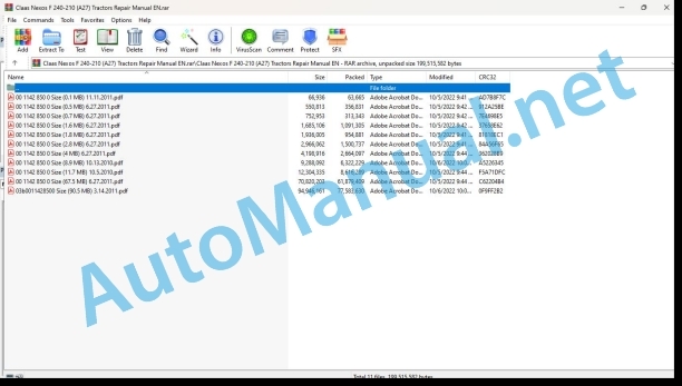
00 1142 850 0 Size (0.1 MB) 11.11.2011.pdf
00 1142 850 0 Size (0.5 MB) 6.27.2011.pdf
00 1142 850 0 Size (0.7 MB) 6.27.2011.pdf
00 1142 850 0 Size (1.6 MB) 6.27.2011.pdf
00 1142 850 0 Size (1.8 MB) 6.27.2011.pdf
00 1142 850 0 Size (11.7 MB) 10.5.2010.pdf
00 1142 850 0 Size (2.8 MB) 6.27.2011.pdf
00 1142 850 0 Size (4 MB) 6.27.2011.pdf
00 1142 850 0 Size (67.5 MB) 6.27.2011.pdf
00 1142 850 0 Size (8.9 MB) 10.13.2010.pdf
03b0011428500 Size (90.5 MB) 3.14.2011.pdf
00 1142 850 0 Size (0.5 MB) 6.27.2011.pdf:
08 POWER TAKE-OFF
CONTENTS
FRONT POWER TAKE-OFF – NEXOS
Tightening torques and sealants
FRONT POWER TAKE-OFF – ELIOS
Tightening torques and sealants
00 1142 850 0 Size (0.7 MB) 6.27.2011.pdf:
09 HYDRAULIC SYSTEM
Hydraulic circuit
Hydraulic circuit 2 pumps with mechanical distributors
Hydraulic circuit 3 pumps with mechanical distributors
Hydraulic ps hydraulic distributors
Mechanical transmission hydraulic circuit
Transmission hydraulic circuit with mechanical reverser and hydraulic doubler
Transmission hydraulic circuit with hydraulic reverser and hydraulic doubler
00 1142 850 0 Size (1.6 MB) 6.27.2011.pdf:
12 CAB / OPERATOR’S PLATFORM
REMOVE AND INSTALL CAB ROOF
REMOVE AND INSTALL PLATFORM
REMOVE AND INSTALL AIR CONDITIONING
00 1142 850 0 Size (11.7 MB) 10.5.2010.pdf:
01 ENGINE – F5C
introduction
Introduction
General notes
General notes on the electrical circuit
Grounding and shielding
Conversions between the main measurement units of the international system and current use derived magnitudes
Engine views
Engine lubrication
Oil pump
Balancing system with counter-rotating counterweights
Oil filter
Oil gas recycling
Water pump
Thermostat
Heat exchanger
Exhaust Gas Recirculation (EGR) system
Supercharging
Fuel supply
Schematic diagram
Hose schematic
Injection pump
Supply phase
Start phase
End of start phase
Engine stop
L.D.A. device (flow adaptation according to the load)
Priming pump
Fuel filter
Engine auxiliary devices
Removing / refitting engine auxiliary devices
Preliminary operations
Finding the TDC on Cylinder 1
BOSCH VE 4/12F pump
Timing gear train casing
Fitting the rear face components
Fitting the flywheel
Fitting the front face components
Engine timing
Piston protrusion measurement
Adjusting the rocker-valve gap
Verifications and checks
Removing-refitting the blow-by on the cylinder head cover
Injection pump removing and refitting procedure
BOSCH VE 4/12F pump
Checking static advance of the injection pump on the engine at TDC of cylinder 1
KSB – Bosch pump link cable
Coolant temperature sensor
Oil pressure switch
KSB coolant temperature sensor
Engine speed sensor
Overhaul of the engine
General specifications
Fitting sets
Removing the connecting rods / pistons / crankshaft and camshafts
Repairing the cylinder block
Checks and measurements
Checking the bearing surface of the cylinder head on the cylinder block
Camshaft
Checking cam lift and cylinder alignment on the shaft
Changing the bush
Followers
Fitting the followers – Camshaft
Crankshaft
Measure the crank pins and journals
Fitting the bearing bushings
Fitting the crankshaft
Checking shoulder gap of the crankshaft
Connecting rod – piston assembly
Piston pin
Connecting rods
Fitting the connecting rod – piston assembly – Connecting rod-piston coupling
Fitting the piston rings
Fitting the connecting rod – piston assemblies in the jackets
Fitting the connecting rod caps
Piston protrusion measurement
Cylinder head
Removing the valves
Checking the cylinder head bearing surface
Valve guide
Valve seats
Fitting the cylinder head
Tightening torques
00 1142 850 0 Size (2.8 MB) 6.27.2011.pdf:
10_Systeme electrique.pdf
10 ELECTRIC SYSTEM
CONTENTS
ERROR CODES
INTRODUCTION
ERROR CODES DISPLAY
Description of the list of error codes
Error code
Transmitter module
Designation
List of error codes
ELECTRIC DIAGRAMS
CLAAS COMPONENT NUMBERS (CCN)
Correspondence between the connectors and the CLAAS COMPONENT NUMBERS (CCN)
W01 – MAIN HARNESS WITHOUT ELECTRO-DISTRIBUTORS
W01 – MAIN HARNESS WITH ELECTRO-DISTRIBUTORS
W02 – ENGINE HARNESS
W03 – TRANSMISSION HARNESS
W04 – VENTILATION AND A/C HARNESS
W05 – LIGHTING HARNESS
W06 – AIR BRAKE HARNESS
W08 – A/C COMPRESSOR ARNESS
W09 – PRIMAY HITCH OFFSET HARNESS
W09_2 – SECONDARY HITCH OFFSET HARNESS
W11 – REAR LIFTING SUPPLY HARNESS
W11_2 – SECONDARY REAR LIFTING HARNESS
W11_2 – PRIMARY REAR LIFTING HARNESS
W11_4 – REAR COMMAND HARNESS OF REAR LIFTING
W12 – SECONDARY HARNESS OF ELECTRO-DISTRIBUTORS
W13 – MAIN HARNESS OF THE ELECTRO-DISTRIBUTORS
00 1142 850 0 Size (4 MB) 6.27.2011.pdf:
06 LIFTING DEVICE
FRONT LIFTING – NEXOS
Tightening torques and sealants
FRONT LIFTING – ELIOS
Tightening torques and sealants
REAR LIFTING
SAFETY INSTRUCTIONS
General safety recommendations
Safety symbols
General precautions
GENERAL INFORMATION
Manual use
Agreements and definitions
General description
GENERAL SPECIFICATIONS
General description
Technical features
Performances
Maintenance
Greasing points
HYDRAULIC SYSTEM
Hydraulic system
Control valve
Neutral phase
Delivery phase
Discharge phase
Cntrol valve sensitivit
Adjustment of the control valve sensitivity
Functioning of the control valve sensitivity
MECHANICAL SYSTEMS
Control levers
Working of the internal leverage system
Functioning with positioning control
Use of control levers
Adjustments
Adjustment of the position control lever
Adjustment of the draft control lever
Control of the reaction spring assembly
Measurement check of the internal push bar
00 1142 850 0 Size (67.5 MB) 6.27.2011.pdf:
02 TRANSMISSION AND GEAR
SAFETY INSTRUCTIONS
General safety recommendations
Safety symbols
General precautions
GENERAL INFORMATION
Manual use
Agreements and definitions
General description
Special recommendations
GENERAL SPECIFICATIONS
Technical Features
Main Features
Tightening torques, sealants and grease application
Assembly typical data
DISASSEMBLY AND ASSEMBLY
4WD drop box
Spring applied hydraulic released
Mechanicl control
Final drive
Final drive 1542 mm and 1242 mm
Final drive 1542 mm and 1242 mm
Final drive 972 mm
Teflon seals replacement (clutch shaft)
Replacement
Upper covers and rockshaft
Disassembly
Assembly
Speed gears outer levers
Disassembly
Assembly
Clutch housing
12+12 Synchro shuttle
24+24 Synchro shuttle – Synchro splitter
24+24 Synchro shuttle – Power splitter
Wet clutches
Power splitter
Synchro splitter
Disassembly
Assembly
HYDRAULIC control PTO cover and clutch
Power take off
HYDRAULIC control PTO input shaft
Output shaft
HYDRAULIC control PTO brake
Ground Drive PTO
MECHANICAL control GROUND DRIVE PTO shaft replacement
PTO coupling group
Slave cylinder
Disassembly
Actuator assembly
Parking brake
Disassembly
Assembly
Housing sensors assy
Disassembly
Assembly
Differential locking control
Disassembly
Assembly
Inner gear control assy
Disassembly
Assembly
Idle gear
Synchro shuttle
Range gears (primary shaft)
Disassembly
Assembly
Input shaft
Synchro shuttle
Synchro shuttle
Disassembly
Assembly
Speed gears (primary shaft)
Synchro shuttle
Differential assy
Disassembly
Assembly
Pinion – Ranges (secondary shaft)
Disassembly
Assembly
Speed gears (secondary shaft)
Disassembly
Assembly
End floats 1 and 2 determination
00 1142 850 0 Size (8.9 MB) 10.13.2010.pdf:
01 ENGINE – CRADLE
introduction
Introduction
General notes
General notes on the electrical circuit
Grounding and shielding
Conversions between the main measurement units of the international system and current use derived magnitudes
Engine lubrication
Oil gas recycling
Supercharging
Fuel supply
injection system
Injection pump
Supply pump
Fuel filter
Engine auxiliary devices
Removing / refitting engine auxiliary devics
Removing engine auiliary devices
Refitting engine auxiliary devices
Removing / fitting the injection pump procedure
Location of the electrical components
Coolant temperature sensor
Water temperature sensor for KSB
Solenoid on the supply pump
Fuel filter
oil pressure switch
Engine speed sensor
Preheating resistor
Overhaul of the engine
General specifications
Fitting sets
Removing the connecting rods / pistons / crankshaft and camshafts
Repairing the cylinder block
Checks and measurements
Checking the bearing surface of the cylinder head and cylinder block
Camshaft
Checking cam lift and the bearing alignment
Changing the bushes
Followers
Fitting the followers – Camshaft
Crankshaft
Measuring the crank pins and journals
Changing the oil pump command gear
Fitting the crankshaft bearing bushings
Measuring the gap between the crankshaft and journals
Checking axial play of the crankshaft
Rod – piston assembly
Piston pins
Conditions for proper pin – piston coupling
Piston rings
Connecting rod
Fitting the connecting rod – piston assembly
Fitting the piston rings
Fitting the connecting rod – piston assemblies in the jackets
Measuring the fitting gap of the connecting rod and crankshaft pin
Piston protrusion check
cylinder head
Removing the valves
Checking cylinder head sealing
Checking the cylinder head bearing surface
Checking and resurfacing the valves
Checking the valve stem valve guide gap and valve centering
Valve guides
Valve housing
Valve springs
Fitting the cylinder head
Tightening torques
03b0011428500 Size (90.5 MB) 3.14.2011.pdf:
03 CHASSIS – NEXOS 2 WHEEL DRIVE
GENERAL INFORMATION
Manual use
Agreements and definitions
General description
Reommendations for repair opertions
SAFETY INSTRUCTIONS
General safety recommendations
Safety symbols
General precautions
GENERAL SPECIFICATIONS
General description
Technical features
Adhesive and tightening torques
disassembly and assembly operations
Steering cylinder group
Disassembly
Assembly
Steering cylinder overhauling
Wheel hub group
Disassembly
Assembly
Wheel hub support group
Disassembly
Assembly
Axle beam group
Disassembly
Assembly
Toe-in / steering angle
Toe-in adjustment
Steering angle adjustment
03 CHASSIS – Nexos F 4 WHEEL DRIVE
SAFETY INSTRUCTIONS
General safety recommendations
WARNING: before proceeding with any operations please read this chapter very carefully.
Safety symbols
General precautions
1 Operate always in a clean and dry environment.
2 Clean carefully the working environment and the machine before carry out the maintenance operations (Fig. 5).
3 Use only cleaning product in agreement with the regulations and always use them in the prescribed way.
4 Do not inhale chemical substances in dangerous concentration for the health care (Fig. 6); ventilate the environments in which sprays and solvents, with volatile chemical substances, are used.
5 Wear suitable clothing and protection such as overalls, safety gloves and ear safety devices (Fig. 7).
WARNING: Safety goggles must always be worn while carrying out every assembling or disassembling operations (Fig. 8).
6 Use suitable ear protection, like ear plugs, to keep out noise and prevent injury to the ears. A prolonged exposure to noise can damage your hearing.
7 The operator must be very careful with the equipment. Do not use headphones to listen music while you are working on the product or on the group.
8 Do not wear slings, ties or other pending clothes. Tie long hair behind the head and/or wear a protective cap.
9 Do not wear rings, armlets, necklaces or other metal objects that are dangerous when current is present.
10 Predispose always the first aid equipment in agreement with the working environments regulations, like the first aid kit (Fig. 9).
11 Keep the phone numbers of a doctor, an ambulance, a hospital and the fire department within reach near the telephone set (Fig. 10). In case of accident it is indispensable to quickly ask for a medical intervention.
12 Keep your hands, feet and clothing away from moving parts of the tool machines. Keep the safety distance from the machine, if it is moving, like during the testing operations (Fig. 11).
13 Light properly the working area by using devices in agreement with the safety regulations (Fig. 12).
14 During the maintenance operations it is strictly forbidden to light free flames (Fig. 13) and smoking (Fig. 14).
15 Always be prepared for fires. Keep the extinguisher within reach. Before start any maintenance operation identify the extinguisher nearest to the working area and the prescribed fire regulations (Fig. 15).
16 The working environment must be always well aired by using devices in agreement with the safety regulations. If local vents a…
GENERAL INFORMATION
Manual use
WARNING: CLAAS warranty does not cover every injury to personnel and damage to product caused by maintenance operations of not authorized personnel and/or by operations not in compliance with CLAAS safety regulations and prescribed procedures.
Agreements and definitions
Note: The notes, pointed out externally to the text they refer, include important information.
WARNING: Warning indications point out the procedures, whose partial or complete non-observance can damage the machine or the connected equipment.
DANGER: Danger indications point out the procedures, whose partial or complete non-observance can injure the operator.
Note: do not follow carefully the CLAAS indications and/or current security regulations can causes serious damages to the persons or to the machines; these damages are not warranty covered.
Note: when this symbol is encountered, it is recommended to follow the described procedure as well as the section Special recommendations warnings.
Note: when this symbol is encountered, it is recommended to follow the described procedure as well as the section Special recommendations warnings.
Note: when this symbol is encountered, it is recommended to follow the described procedure as well as the section Special recommendations warnings.
Note: do not follow carefully the CLAAS indications can causes serious damages to the machine; these damages are not warranty covered.
Note: when this symbol is encountered, it is recommended to follow the described procedure as well as the section Special recommendations warnings.
General description
Note: in case of replacement of one part of the bevel gear set this operation requires the replacement of the other part too.
Special recommendations
WARNING: do not use a hammer directly on the seals.
WARNING: disposal of used oil must be done according to laws.
GENERAL SPECIFICATIONS
General description
Technical features
Adhesives and tightening torques
Note: apply only on indicated side
Disassembly and Assembly
Steering cylinder group
Disassembly
Assembly
Epicyclic reduction gear group
Disassembly
Assembly
Wheel hub group
Disassembly
Assembly
Axle beam group
Disassembly
Assembly
Flange group
Disassembly
Assembly
Trunnions group
Disassembly
Assembly
Differential support group
Disassembly
Assembly
Bevel gear marking test
Differential group
Differential
Pinion group
Disassembly
Assembly
Toe-in / steering angle
Toe-in adjustment
Steering angle adjustment
03 CHASSIS – Nexos VL 4 WHEEL DRIVE
GENERAL INFORMATION
Manual use
Agreements and definitions
General description
Recommendations for repair operations
SAFETY INSTRUCTIONS
General safety recommendations
Safety symbols
General precautions
GENERAL SPECIFICATIONS
General description
Technical Features
Adhesives and tightening torques
DISASSEMBLY AND ASSEMBLY OPERATIONS
Steering cylinder group
Disassembly
Assembly
Epicyclic reduction gear group
Disassembly
Assembly
Wheel hub group
Disassembly
Assembly
Axle beam group
Disassembly
Assembly
Flange group
Disassembly
Assembly
Differential support group
Disassembly
Assembly
Bevel gear marking test
Differential group
Disassembly
Assembly
Pinion group
Disassembly
Assembly
Toe-in/steering angle
Toe-in adjustment
Steering angle adjustment
03 CHASSIS – Nexos VE 4 WHEEL DRIVE
SAFETY INSTRUCTIONS
General safety recommendations
Safety symbols
General precautions
GENERAL INFORMATION
Manual use
Agreements and definitions
General description
Special recommendations
GENERAL SPECIFICATIONS
General description
Technical features
Adhesives and tightening torques
Disassembly and Assembly
Steering cylinder group
Disassembly
Assembly
Wheel hub group
Disassembly
Assembly
Epicyclic reduction gear group
Disassembly
Assembly
Axle beam group
Disassembly
Assembly
Flange group
Disassembly
Assembly
Differential support group
Disassembly
Assembly
Bevel gear marking test
Differential group
Disassembly
Assembly
Pinion group
Disassembly
Assembly
Toe-in / steering angle
Toe-in adjustment
Steering angle adjustment
John Deere Repair Technical Manual PDF
John Deere Repair Technical Manual PDF
John Deere Repair Technical Manual PDF
John Deere 18-Speed PST Repair Manual Component Technical Manual CTM168 10DEC07
John Deere Repair Technical Manual PDF
John Deere DF Series 150 and 250 Transmissions (ANALOG) Component Technical Manual CTM147 05JUN98
John Deere Repair Technical Manual PDF
John Deere Parts Catalog PDF
John Deere Tractors 7500 Parts Catalog CPCQ26568 30 Jan 02 Portuguese
John Deere Repair Technical Manual PDF
John Deere Repair Technical Manual PDF
John Deere PowerTech M 10.5 L and 12.5 L Diesel Engines COMPONENT TECHNICAL MANUAL CTM100 10MAY11
John Deere Repair Technical Manual PDF
John Deere POWERTECH E 4.5 and 6.8 L Diesel Engines TECHNICAL MANUAL 25JAN08
John Deere Repair Technical Manual PDF

