Claas Nexos F 240-210 (A27) Tractors Repair Manual ES
$100.00
- Model: Nexos F 240-210 (A27) Tractors
- Type Of Manual: Repair Manual
- Language: ES
- Format: PDF(s)
- Size: 239 MB
File List:
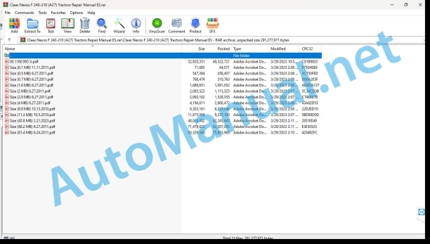
00 1160 993 X.pdf
Size (0.1 MB) 11.11.2011.pdf
Size (0.5 MB) 6.27.2011.pdf
Size (0.7 MB) 6.27.2011.pdf
Size (1.6 MB) 6.27.2011.pdf
Size (11.3 MB) 10.5.2010.pdf
Size (2 MB) 6.27.2011.pdf
Size (2.9 MB) 6.27.2011.pdf
Size (4 MB) 6.27.2011.pdf
Size (45.8 MB) 2.21.2023.pdf
Size (68.2 MB) 6.27.2011.pdf
Size (8.9 MB) 10.13.2010.pdf
Size (81.4 MB) 6.24.2011.pdf
00 1160 993 X.pdf:
Repair manual
CCN (CLAAS COMPONENT NUMBER)
Introduction
General information
Using this repair manual
Validity of the repair manual
General repair instructions
Technical characteristics
Cause of damage
Interchange parts
Diesel engine
Generator
Welding work
Drive belt/drive chains
Conical ring assemblies
Self-locking screws with microencapsulated glue
Thread braking
Tightening ring bearing
Tightening sleeve bearing
Threaded fittings with cutting ring in hydraulic lines
Threaded fittinrin hydraulic lines
Biconical threaded fittings in hydraulic conduits
Hydraulic hoses
Hose route
Tips for an economical repair
Tightening torques
Tightening torques for metric threads according to standard NF E25-030-1 2007-12-01
Tightening torques for hydraulic fittings CLAAS standard CN 02 0225
Tightening torques for hydraulic threaded fittings and air conditioning threaded fittings with sealing cone and O-ring DIN 3865
Tightening torques for hydraulic threaded fittings DIN 3901
Tightening torques for adjustable hydraulic threaded fittings ISO 6149-2/ISO 11926-2 (3)
Tightening torques for pivoting hydraulic threaded fittings
Tightening torques for hollow screws DIN 7643
Technical data
Lubricants
01 Engine
0102 Complete component
Engine identification
Introduction
General observations
Engine and front axle
Disassembly
Preliminary operation
0125 Fuel/injection system
Fuel level indicator
Disassembly
Fuel tank
Disassembly
Mounting
0135 Cooling system
Radiator
Radiator disassembly
Disassembly
Mounting
Fan belt
Exploded view
Disassembly
Mounting
0145 Air suction
Air filter
Disassembly
0150 Engine coupled parts
Starting motor
Disassembly
Mounting
Alternator
Disassembly
Mounting
01 Engine
0102 Complete component
Complete engine (NEF)
General characteristic (NEF)
Engine tightening torques (NEF)
Engine disassembly
Engine mounting
0110 Engine casing
Oil pan tightening torques (NEF)
Oil pan (NEF)
Disassembly
Mounting
Timing Gear Train Case (NEF)
Engine flywheel housing (NEF)
Disassembly
Assembly of components
Cylinder block repair (NEF)
Checks and measurements
Checking the contact surface of the cylinder head on the cylinder block
0115 Engine propulsion
General characteristic (NEF)
Tightening torques (NEF)
General engine overhaul (NEF)
Crankshaft (NEF)
Disassembly
Measuring the journals and journals
Tolerance
Mounting
Mounting the bearing half-shells
Checking the crankshaft axial play
Engine flywheel (NEF)
Disassembly
Crankshaft pulley (NEF)
Disassembly
Mounting
Crankshaft bearing seals (NEF)
special tool
Disassembling the front and rear bearing seals
Mounting
Connecting rod-piston assembly (NEF)
Disassembly
Checking the piston – Features
Shaft and piston pairing
Segments
Checking the segments
Characteristics
Assembly of the connecting rod-piston assembly. Connecting rod-piston coupling
Assembly of the segments
Assembly of the connecting rod and piston assembly in the cylinder
Installing the connecting rod caps
Piston protrusion check
Balancer (NEF)
Disassembly
Mounting
0120 Cylinder head / valves / distributor wheel
Valve – Cylinder head — (NEF)
Characteristics
Tightening torques (NEF)
Cylinder head (NEF)
Disassembly
Checking the tightness of the cylinder head
Checking the cylinder head support flatness
Valves (NEF)
Valve disassembly
Main dimensions of the intake and exhaust valves
Stripping, checking and grinding of valves
Checking the play between the valve rods and the valve seat in the cylinder head and the centering of the valves
Valve housing
Replacing valve housings
Valve seats
Main dimensions of valve seats (mm)
Valve springs
Cylinder head mounting
Special tools
Rocker cover (NEF)
Disassembly
Mounting
Rocker arm ramp (NEF)
Disassembly
Characteristics
Mounting
Adjusting the rocker arm play
Final operations
Camshaft (NEF)
Characteristics
Disassembly
Checking Cam Lift and Shaft Bearing Alignment
Main mensions of t camshaft rings and their seats
Special tools
Replacing the rings
Installing the tappets – Camshaft (NEF)
Timing sprocket (NEF)
Disassembly
Engine Mounting and Timing
0125 Fuel/injection system
Tightening torques (NEF)
Low pressure fuel line (NEF)
Disassembly
Fuel filter holder (NEF)
Disassembly
Mounting
Fuel lines from the high pressure pump to the injectors (NEF)
Disassembly
Mounting
Injection pump (NEF)
Preliminary operations
Locating top dead center with tool #77 0138 816 9
Locating the top dead center with tool #00 1130 892 0 – False injector
Checking the injection pump timing
Injector (NEF)
Preliminary operation
Disassembly
Mounting
0130 Lubricating oil system
Tightening torques (NEF)
Oil filter (NEF)
Disassembly
Mounting
Oil pump (NEF)
Disassembly
Mounting
Engine Oil Heat Exchanger (NEF)
Preliminary operation
Disassembly
Mounting
Oil vapor circulation (NEF)
Disassembly
Mounting
0135 Cooling system
Tightening torques (NEF)
Drive belt (NEF)
Disassembly
Mounting
Water pump (NEF)
Disassembly
Mounting
Thermostat (NEF)
Disassembly
Mounting
0140 Exhaust gas system
Tightening torques (NEF)
Turbocharger (NEF)
Disassembly
Mounting
Exhaust manifold (NEF)
Disassembly
Mounting
0145 Air suction
Tightening torques (NEF)
Intake manifold (NEF)
Disassembly
Mounting
0150 Engine coupled parts
Tightening torques (NEF)
Alternator (NEF)
Disassembly
Mounting
Starter motor (NEF)
Disassembly
Mounting
0155 Engine adjustment
Tightening torques (NEF)
Engine management module (NEF)
Preliminary operation
Disassembly
Mounting
NEF motor wiring
Disassembly
Mounting
Glow plug (NEF)
Disassembly
Mounting
01 Engine
0102 Complete component
Complete engine (F5C)
General characteristic (F5C)
Engine tightening torques (F5C)
Engine disassembly
Engine mounting
Engine mounting
0110 Engine casing
Oil pan tightening torques (F5C)
Oil pan (F5C)
Disassembly
Mounting
Timing Gear Train Case (F5C)
Disassembly
Mounting
Engine flywheel housing (F5C)
Assembling the rear face components
After having applied the sealing product, the pieces must be assembled within 10 minutes maximum.
Cylinder block repair (F5C)
Checks and measurements
Checking the contact surface of the cylinder head on the cylinder block
Checking the alignment of the oil pan in the engine crankcase
0115 Engine propulsion
General characteristic (F5C)
Tightening torques (F5C)
General engine overhaul (F5C)
Crankshaft (F5C)
Disassembly
Measuring the journals and journals
Crankshaft journals and hands – Measured values
Tolerances
Crankshaft assembly
Mounting the bearing shells
Checking the crankshaft axial play
Engine flywheel (F5C)
Disassembly
Mounting
Crankshaft pulley (F5C)
Disassembly
Preliminary operations
Mounting
Crankshaft bearing seals (F5C)
special tool
Disassembling the front and rear bearing seals
Mounting
Connecting rod-piston assembly (F5C)
Disassembly
Checking the piston – Features
Shaft and piston pairing
Segments
Checking the segments
Characteristics
Assembly of the connecting rod-piston assembly. Connecting rod-piston coupling
Assembly of the segments
Assembly of the connecting rod and piston assembly in the cylinder
Installing the connecting rod caps
Piston protrusion measurement
Balancer (F5C)
Disassembly
Mounting
0120 Cylinder head / valves / distributor wheel
Valve – Cylinder head —F5C)
Characteristics
Tightening torques (F5C)
Cylinder head (F5C)
Disassembly
Checking the cylinder head bearing surface
Cylinder head assembly
Valves (F5C)
Valve disassembly
Main dimensions of the intake and exhaust valves
Stripping, checking and grinding of valves
valve guide
Replacing valve guides
Valve seats
Main dimensions of valve seats (mm)
Cylinder head mounting
Special tools
Rocker cover (F5C)
Disassembly
Mounting
Rocker arm ramp (F5C)
Preliminary operation
Characteristics
Adjusting the rocker arm play
Final operation
Camshaft (F5C)
Characteristics
Main dimensions of the camshaft bearings
Checking Cam Lift and Shaft Bearing Alignment
Main dimensions of the camshaft rings and their seats
Special tools
Replacing the rings
Mounting of the pushers
Synchronization (F5C)
Fiing the top dead center of cylinder #1
0125 Fuel/injection system
Tightening torques (F5C)
Low pressure fuel line (F5C)
Disassembly
Fuel filter (F5C)
Disassembly
Mounting
Fuel lines from the high pressure pump to the injectors (F5C)
Disassembly
Mounting
Pump “Bosch VE 4/12 F” (F5C)
Disassembly
Mounting
Injectors (F5C)
Disassembly
Mounting
Fuel cooler (F5C)
Disassembly
Mounting
0130 Lubricating oil system
Tightening torques (F5C)
Engine oil filter (F5C)
Disassembly
Mounting
Oil pump (F5C)
Disassembly
Mounting
Oil filter (F5C)
Preliminary operation
Disassembly
Mounting
Engine Oil Heat Exchanger (F5C)
Preliminary operation
Disassembly
Mounting
Oil vapor circulation (F5C)
Disassembly and assembly of the “blow-by” in the cylinder head cover
Disassembly
Mounting
0135 Cooling system
Tightening torques (F5Cive Belt (F5C)
Mounting
Ventilation (F5C)
Disassembly
Mounting
Water pump (F5C)
Disassembly
Mounting
Thermostat (F5C)
Disassembly
Mounting
0140 Exhaust gas system
Tightening torques (F5C)
Vertical exhaust pipe (F5C)
Disassembly
Mounting
Turbocharger (F5C)
Preliminary operation
Disassembly
Mounting
Exhaust manifold (F5C)
Preliminary operation
Disassembly
Mounting
0145 Air suction
Tightening torques (F5C)
Intake manifold (F5C)
Preliminary operation
Disassembly
Mounting
0150 Engine coupled parts
Tightening torques (F5C)
Alternator (F5C)
Disassembly
Mounting
Starter motor (F5C)
Disassembly
Mounting
0155 Engine adjustment
Tightening torques (F5C)
“ECU” module (F5C)
Disassembly
Mounting
Motor wiring (F5C)
Disassembly
Mounting
Motor wiring (F5C)
Disassembly
02 Gears / clutch / cn shaft
0202 Complete component
Special transmission tools
Mechanical inverter 12/12 and 24/24
24/24 Mechanical Inverter and Duplicator
Hydraulic duplicator 24/24 and 24/12
Hydraulic reverser 24/12
Reducer casing
Final reduction standard version
Final reduction reinforced version
Hydraulic Control Front Axle Clutch
Front axle hydraulic clutch
Tightening, sealing and greasing torques
Application of lubricants and sealing products
Joint sealing products
Thread braking
Fixing adhesive
Grease during assembly
Greasing the gearbox input shaft and power take-off shaft
Front axle clutch housing with hydraulic control
Front axle clutch housing with mechanical control
Transmission clutch housing 12/12
24/24 Transmission Clutch Housing with Mechanical Control Duplicator
24/24 Transmission Clutch Housing with Hydraulic Control Duplicator
Transmission clutch housing 24/12
Reducer casing
Standard final reduction
Reinforced final reduction
Narrow final reduction
Short final reduction
Super short final reduction (892 mm)
Brake control group (valid for all models)
Internal gearbox control
External reducer control
Bottom and top covers
Assembly Features
All transmission models
Transmission 12/12
24/24 transmission with mechanical duplicator
24/24 transmission with hydraulic doubler
Transmission 12/24
Separating the engine from the clutch housing
Disassembly
Mounting
Top covers and riser
Exploded view
Disassembly
Mounting
0215 Mechanical clutch
clutch housing
Disassembly
Preliminary operation
clutch adjustment
12” mechanical clutch
11” mechanical clutch
Transmission with hydraulic doubler – Clutch shaft
Replacing “Teflon” gaskets – Exploded view
Replacing Teflon gaskets
Trans12/24
24/24 transmissioydraulic doubler
24/12 and 24/24 transmissions with hydraulic doubler
Transmission 12/24
24/24 transmission with hydraulic doubler
24/12 and 24/24 transmissions with hydraulic doubler
Air Compressor – Transmission 24/12
Exploded view
Disassembly
Mounting
0218 Clutch control/operation
Clutch and shuttle controls. Transmission 12/12
Mechanical inverter without duplicator – Exploded view
Disassembly
Mounting
Clutch and shuttle controls. 24/24 transmission (mechanical reverser and doubler)
Mechanical inverter and duplicator. Exploded view
Disassembly
Mounting
Axial play adjustment
Clutch and shuttle controls – 24/24 transmission (mechanical shuttle and hydraulic doubler)
Mechanical reverser and hydraulic duplicator – Exploded view
Disassembly
Mounting
Upper shaft axial play adjustment
Clutch and shuttle controls – Transmission 24/12
Exploded view
Disassembly
Mounting
Upper shaft axial play adjustment
Inverter shaft axial play adjustment
Clutch clearance adjustment
0220 Mechanical investment
Controls – Mechanical inverter
Exploded view
Disassembly
Transmission 12/24
Mounting
Transmission 12/24
Synchro reverser idler gear
Exploded view
Disassembly
Mounting
0222 Hydraulic inversion
Hydraulic reverser
Exploded view
Disassembly
Mounting
Game adjustment
idler sprocket
Exploded view
Disassembly
Mounting
Mechanical inverter adjustment
Disassembly
Mounting
0230 Mechanical gear
Input shaft – Transmission with mechanical shuttle
Exploded view
Disassembly
Mounting
Input shaft – Transmission with hydraulic shuttle
Exploded view
Disassembly
Mounting
Primary shaft – Speeds – Transmissions with mechanical shuttle
Exploded view
Disassembly
Mounting
Primary shaft – Speeds – Transmission 24/12
Exploded view
Disassembly
Mounting
Determination of axial clearance
Primary shaft – Ranges
Exploded view
Disassembly
Mounting
Secondary Axle – Speeds
Exploded view
Disassembly
Mounting
Secondary axis – Ranges
Exploded view
Disassembly
Mounting
Primary shaft covers
Transmission 12/12 – Section
24/24 transmission with inverter and mechanical duplicator – Section
24/24 transmission with mechanical shuttle and hydraulic doubler – Section
Transmission 12/24 – Section
Secondary shaft – Axial play measurement
mechanical duplicator
Exploded view
Disassembly
Mounting
0234 Load Switching Gear
hydraulic duplicator
Exploded view
Disassembly
Mounting
Disc pack wear
0238 Gearbox control/drive
External controls
Exploded view
Disassembly
Mounting
External controls – Nexos
Exploded view
Disassembly
Mounting
Interior controls
Transmission 12/12 and 24/24 – Exploded view
Interior controls – Transmission 24/12
Disassembly
Forward/reverse gear
Mounting
0240 Rear axle housing
Trumpet and final reductions standard version
Exploded view
Disassembly
Mounting
Axial play adjustment
Trumpet and final reductions reinforced version 506 UP 6/1
Exploded view
Disassembly
Mounting
Preload of tapered roller bearings
Trumpet and short version final reductions (972 mm)
Exploded view
Disassembly
Mounting
Preload of tapered roller bearings
Trumpet and final reductions of super short version (872 mm)
Exploded view
Disassembly
Mounting
Preload of tapered roller bearings
0242 Differential
Differential
Exploded view
Disassembly
Mounting
For 12/12 model transmissions
In all transmissions of the 24/24 and 24/12 models with final drive except the narrow version
Only for 24/24 and 24/12 model transmissions with narrow version final drive (1242 mm)
Differential lock control
Exploded view
Disassembly
Mounting
0248 Rear axle control/drive
Transmission sensors
Exploded view – Location
Sensors/transmissions applicability
Disassembly
Description
Mounting
0250 Mechanical drive of the front axle
Front axle mechanical clutch
Exploded view
Disassembly
Mounting
0252 Electrohydraulic drive of the front axle
Hydraulic Control Front Axle Clutch
Exploded view
Disassembly
Mounting
Solenoid valve block
Disassembly
Mounting
0255 Cooling system gear box
oil cooler
Disassembly
Mounting
0260 Cardan shaft
Front axle drive shaft
Disassembly
03 Chassis
0310 Axle
Recommendations – Maintenance and repair
tree joints
Adjustment shims
Bearings
Plugs and rivets
Plastic caps and protections
Slotted Safety Pins
Adhesives and sealing products
Oil drain
Cleaning
Disc ends and special tools
Use of lubricants
0320 Steering axle
Tightening torques, lubricants and sealing products (two-wheel drive)
Joint sealing products
Application of lubricants and sealing products
Main dimensions (mm)
Adhesives and tightening torques
Front bridge
Disassembly
Steering cylinder (two-wheel drive)
Exploded view
Disassembly
Mounting
Repair of steering cylinders
Exploded view
Disassembly of the steering cylinder
Steering cylinder assembly
wheel hub
Exploded view
Disassembly
Mounting
Preliminary operations
Wheel hub support
Exploded view
Disassembly
Mounting
Preliminary operations
shaft body
Exploded view
Disassembly
Preliminary operations
Mounting
Pinch and rotation angle
Exploded view
Pinch Adjustment
Turning angle adjustment
0325 Front drive steering axle
Torque, lubricants and sealing products (four-wheel drive)
Joint sealing products
Thread braking
Fixing adhesive
Application of lubricants and sealing products
Technical characteristics of the four-wheel drive bridge. Nexus «F»
Main dimensions (mm)
Adhesives and tightening torques
Technical characteristics of the four-wheel drive front axle. «VE» Links
Main dimensions (mm)
Adhesives and tightening torques
Technical characteristics of the four-wheel drive bridge. «VL» Nexus
Main dimensions (mm)
Adhesives and tightening torques
Features of Limited Displacement Differential Discs
Steering cylinder • Links «F», «VE», «VL»
Exploded view
Disassembly of the steering cylinder
Steering cylinder assembly
Epicyclic reduct
Exploded view
Disassemblclic reduction
Mounting the epicyclic reduction
Epicyclic reduction. «VE» Links
Exploded view
Disassembly
Preliminary operations
Mounting
Epicyclic reduction. «VL» Nexus
Exploded view
Disassembly
Mounting
Wheel hub • Nexos «F», «VL»
Exploded view
Disassembling the wheel hub «F», «VL»
Preliminary operations
Preliminary operations
Wheel hub assembly • Nexos «F», «VL»
Wheel hub • Nexos «VE»
Exploded view
Disassembly
Mounting
Board. Bearing assembly. Support • Nexus «F»
Exploded view
Disassembly
Mounting
Disk • Links «F», «VL»
Exploded view
Disassembly
Mounting
Disk • Nexus «VE»
Exploded view
Disassembly
Mounting
Differential case • Nexos «F», «VL»
Exploded view
Disassembly
Mounting
Assembly with newdjusting the tooth clearance
Checking the conerential case • Nexos «VE»
Exploded view
Disassembly
Preliminary operations
Mounting
Tooth gap clearance adjustment
If the bearings have not been replaced
If the bearings have been replaced
Alternative procedure after adjusting the tooth clearance
Disassembly
Checking the contact mark of the differential teeth
Differential • Links «F», «VL»
Exploded view
Differential disassembly • Nexos «F», «VL»
Preliminary operations
Differential assembly • Nexos «F», «VL»
Additional operation in Nexos «F»
Differential • “VE” links
Exploded view
Differential disassembly • Nexos «VE»
Preliminary operations
Mounting
attack pinion
Special tools
Exploded view
Disassembly of the drive pinion
Preliminary operations
Drive pinion assembly
n Nexos «F», «VL»
Operation that must be carried out in Nexos «VE»
If the If the bearings have been replaced
Alternative procedure. «VE» Links
Alternative procedure
Front axle body • Links «F», «VL»
Special tools
Exploded view
Disassembly of the front axle body
Front axle body assembly
Front axle body • Nexos «VE»
Special tools
Exploded view
Disassembly
Preliminary operations
Mounting
Pinch and rotation angle
Exploded view
Pinch Adjustment
Turning angle adjustment
0340 Front wheels
front wheels
Disassembly
04 Brake
0405 Service brake
brake cylinder
Disassembly
Mounting
0415 Parking brake
06 Lifting device
0605 Rear linkage
Rear Linkage Features
Product identification
Description
Main elements of the elevator
Technical characteristics
Main dimensions (mm)
Benefits
Disassembly
Mounting
Rear linkage adjustments
Sensitivity adjustment valve
Position control lever
Effort c
Rear linkage controls
Reaction spring assembly
Internal push bar
Lifting arm and cylinder
Exploded view
Disassembly
Mounting
Rear linkage control linkage
Exploded view
Disassembly
Inspection and assembly
Rear linkage main control
Disassembly
Mounting
Rear linkage plastic ring
Exploded view
Preliminary operations
Position control lever ring
Disassembly
Mounting
Effort control lever ring
Disassembly
Mounting
Effort and position control control linkage
Exploded view
Disassembly
Mounting
Rear hydraulic linkage distributor
Exploded view
Preliminary operations
Disassembly
Solenoid valves
Closing plate
Rear linkage shock valve
Retention valve
pressure balance
Mounting
0610 Front linkage
Front lift
Exploded view of mechanical components
Exploded view of hydraulic components
Tightening torques
Preliminary operation
Mounting
0615 Front loader
Front loader frame
08 Drives
0802 Rear PTO
Tightening, sealing and greasing torques
Application of lubricants and sealing products
Joint sealing products
Thread braking
Fixing adhesive
Grease during assembly
Power take-offs with mechanical control or proportional to the forward speed – “12/12” and “24/24” transmission
Hydraulically controlled power take-offs – “24/12” transmission
Rear PTO clutch stop adjustment
0804 Front power take-off
Front PTO – Elios
Exploded view
Tightening torques and sealing products
Preliminary operation
Mounting
Front PTO – Nexos
Exploded view
Tightening torques
Preliminary operation
Mounting
09 Hydraulics
0910 Bombs
Hydraul Disassembly
Mounting
0920 Valves
pressure limiter
Exploded view
Preliminary operations
Disassembly
Cleaning
Rear distributor lock
Exploded view
Preliminary operations
Disassembly
Mounting
12 Driver’s cab/platform
1210 Cabin
Disassembly of the cabin
Cabin roof
Preliminary operation
Disassembly
1215 Driver’s platform
Platform and arch
Preliminary operation
Disassembly
1240 Air conditioning equipment
80 Attached parts, machine casing
8025 Coverings / hoods
Side covers
Disassembly
Mounting
8035 Counterweight / additional weight
dough holder
Disassembly
Size (0.5 MB) 6.27.2011.pdf:
08 POWER OUTPUT
FRONT POWER TAKE OFF – NEXOS
Tightening torques and sealing productsf
FRONT POWER TAKE OFF – ELIOS
Tightening torques nd sealing products
Size (0.7 MB) 6.27.2011.pdf:
09 HYDRAULIC SYSTEM
Hydraulic circuit
Hydraulic circuit 2 pumps with mechanical distributors
Hydraulic circuit 3 pumps th mechanical distributors
Hydraulic circuit 3 pumps with electrohydraulic distributors
Mechanical transmission hydraulic circuit
Hydraulic transmission circuit with mechanical reverser and hydraulic duplicator
Hydraulic transmission circuit with hydraulic reverser and hydraulic duplicator
Size (1.6 MB) 6.27.2011.pdf:
12 CABINA / PLATAFORMA DEL OPERADOR
CONTENIDO
RETIRAR E INSTALAR EL TECHO DE LA CABINA
RETIRAR E INSTALAR LA PLATAFORMA
RETIRAR E INSTALAR EL AIRE ACONDICIONADO
Size (11.3 MB) 10.5.2010.pdf:
01 ENGINE – F5C
introduction
Introduction
General observations
General observations on the electrical circuit
Mass and shielding
Conversions between the main units of measurement of the international system and the commonly used derived quantities
Generalities
Engine views
Engine lubrication
Oil pump
Counter-rotatg riser balancing system
Oil filter
Recycling of oil vapors
Refrigeration
Water Pump
Thermostat
Heat exchanger
EGR (Exhaust Gas Recirculation) exhaust gas recirculation system
Overfeeding
fuel supply
Principle scheme
Tube diagram
injection pump
Feeding phase
Startup phase
End of start phase
Engine stop
L.D.A. device (flow adaptation depending on load)
priming pump
fuel filter
Engine peripherals
Disassembly/assembly of engine peripherals
Preliminary operations
Cylinder 1 PMH Search
BOSCH VE 4/12F pump
Timing Gear Train Case
Assembly of rear surface components
Steering wheel assembly
Assembly of front surface components
Distribution draft
Piston overflow measurement
Rocker-valve clearance adjustment
Verifications and controls
Disassembly-reassembly of the blow-by in the cylinder head cover
Disassembly and reassembly procedure for the injection pump
BOSCH VE 4/12 F pump
Control of the static advance of the injection pump in the engine in PMH of cylinder 1
KSB connection cable – Bosch pump
Coolant temperature sensor
Oil pressure switch
KSB coolant temperature sensor
Engine speed sensor
General engine inspection
General characteristics
Mounting clearances
Disassembly of connecting rods / pistons / crankshaft and camshafts
Cylinder block repairs
Controls and measurements
Checking the bearing surface of the cylinder head on the cylinder block
Distribution
Camshaft
Cam lift control and shaft cylinder alignment control
Replacing the bushing
Installing the tappets – Camshaft
Crankshaft
Measurement of trunnions and cranks
Mounting the support bearings
Crankshaft assembly
Checking crankshaft shoulder clearance
Connecting rod – piston assembly
piston shaft
Bushings
Assembly of the connecting rod-piston assembly – Connecting rod-piston coupling
Assembly of the segments
Assembly of the connecting rod-piston assemblies inside the liners
Installing the connecting rod caps
Piston overflow measurement
Valve disassembly
Checking the cylinder head bearing surface
Valve guide
valve seats
Cylinder head assembly
Tightening torques
Size (2.9 MB) 6.27.2011.pdf:
ERROR CODES
INTRODUCTION
DISPLAY ERROR CODES
Description of the list of error codes
Error code
Emitter module
Designation
List of error codes
ELECTRIC SCHEMES
CLAAS COMPONENT NUMBERS (CCN) LIST
Correspondence between connectors and CLAAS COMPONENT NUMBERS (CCN)
W0 – MAIN BEAM WITHOUT ELECTRIC DISTRIBUTORS
W01 – MAIN BEAM WITH ELECTRODISTRIBUTORS
W02 – ENGINE BEAM
W03 – TRANSMISSION BEAM
W04 – VENTILATION AND AIR CONDITIONING BUMPER
W05 – LIGHTING BEAM
W06 – PNEUMATIC BRAKE BEAM
W08 – AIR CONDITINING COMPRESSOR BEAM
W09 – HITCH DEPORTATION MAIN BEAM
W09_2 – SECONDARY BEAM OF HITCH DEPORTATION
W11 – REAR LIFT SUPPLY BEAM
W11_2 – REAR LIFT SECONDARY BEAM
W11_3 – REAR LIFT MAIN BEAM
W11_4 – REAR CONTROL BEAM OF THE REAR LIFT
W12 – SECONDARY BEAM OF THE ELECTRIC DISTRIBUTORS
W13 – MAIN BEAM OF THE ELECTRIC DISTRIBUTORS
Size (4 MB) 6.27.2011.pdf:
06 LIFTING DEVICE
FRONT LIFT – NEXOS
Tightening torques and sealants
FRONT LIFT – ELIOS
Tightening torques and sealants
REAR LIFT
SECURITY INSTRUCTIONS
General safety recommendation
John Deere Repair Technical Manual PDF
John Deere Repair Technical Manual PDF
John Deere 18-Speed PST Repair Manual Component Technical Manual CTM168 10DEC07
John Deere Repair Technical Manual PDF
John Deere Repair Technical Manual PDF
John Deere PowerTech M 10.5 L and 12.5 L Diesel Engines COMPONENT TECHNICAL MANUAL CTM100 10MAY11
John Deere Repair Technical Manual PDF
John Deere Repair Technical Manual PDF
John Deere Diesel Engines POWERTECH 2.9 L Component Technical Manual CTM126 Spanish
John Deere Repair Technical Manual PDF
John Deere Repair Technical Manual PDF
John Deere Parts Catalog PDF
John Deere Tractors 7500 Parts Catalog CPCQ26568 30 Jan 02 Portuguese

