Claas Orbis 900 (992) Forage Harvesters Operator Manual ES
$50.00
- Model: Orbis 900 (992) Forage Harvesters
- Type Of Manual: Operator Manual
- Language: ES
- Format: PDF(s)
- Size: 78.0 MB
File List:
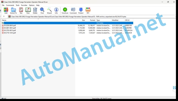
00 0290 666 8.pdf
00 2601 384 3.pdf
00 2702 465 0.pdf
00 2716 134 0.pdf
00 0290 666 8.pdf:
ORBIS 900
1. Introduction
1.1 Information regarding the instruction manual
1.1.1 Validity of the manual
1.1.2 Information relating to this instruction manual
1.1.3 Symbols and indications
1.1.4 Optional equipment
1.1.5 Qualified specialized workshop
1.1.6 Maintenance instructions
1.1.7 Information regarding warranty
1.1.8 Spare parts and technical issues
1.2 Proper application of the machine
1.2.1 Proper machine application
1.2.2 Logically foreseeable inappropriate application
2 Security
2.1 Recognize warning signs
2.1.1 Danger symbols
2.1.2 Keyword
2.2 Safety instructions
2.2.1 Meaning of the instruction manual
2.2.2 Observe graphic danger symbols and alarm indications
2.2.3 Requirements for all people working with the machine
2.2.4 Children in danger
2.2.5 Danger zones
2.2.6 Position yourself between the machine and the head
2.2.7 Couple the machine with the head
2.2.8 Risk of injury due to rotating shafts
2.2.9 Construction changes
2.2.10 Optional equipment and spare parts
2.2.11 Control of the machine in operation
2.2.12 Use only after correct start-up
2.2.13 Technical status
2.2.14 Danger due to machine breakdowns
2.2.15 Comply with technical limit values
2.2.16 Danger due to coasting parts
2.2.17 Keep protective devices operational
2.2.18 Personal protective equipment
2.2.19 Wear appropriate clothing
2.2.20 Remove dirt and loose objects
2.2.21 Prepare the machine for road traffic
2.2.22 Dangers when driving on the road and in the countryside
2.2.23 Park the machine safely
2.2.24 Unsuitable consumables
2.2.25 Safe handling of consumables and auxiliary materials
2.2.26 Environmental protection and waste disposal
2.2.27 Fire protection
2.2.28 Electrical shock from electrical equipment
2.2.29 Liquids under pressure
2.2.30 Hot surfaces
2.2.31 Work only on the stopped machine
2.2.32 Maintenance work and repair work
2.2.33 Machine parts and lifted loads
2.2.34 Danger from welding work
2.3 Safety signage
2.3.1 Structure of graphic hazard symbols
2.3.2 Position of warning symbols on the machine
3 Machine Description
3.1 Summary and operation
3.1.1 Machine overview
3.1.2 Drive diagram
3.1.3 Summary of clutches
3.1.4 Machine operating mode
3.2 Optional equipment
3.2.1 Reversible input gear*
3.2.2 Switchable input gear*
3.2.3 Transport system*
3.2.4 AUTO CONTOUR*
3.2.5 AUTOPILOT*
3.2.6 Additional weights*
3.2.7 3-channel belt drive*
3.2.8 Conveyor cone*
3.2.9 Tip extension*
3.2.10 Legal equipment France*
3.2.11 Wear plates for skids*
3.2.12 Skate coating*
3.2.13 Support legs*
3.2.14 Support legs*
3.3 Identification plates and vehicle identification number
3.3.1 Machine identification plate
3.4 Machine information
3.4.1 Adhesive on the machine
4 Control and display instruments
4.1 Control elements
4.1.1 Gears
4.1.2 Tilting chassis
4.1.3 Laying corn auger
4.1.4 Assembled parts and machine casing
5 Technical data
5.1 ORBIS 900
5.1.1 Suitable machines
5.1.2 Dimensions
5.1.3 Weights
5.1.4 Tire pressure
5.1.5 Reaction torques of safety clutches
5.1.6 Lubricants
6 Preparation of the machine
6.1 Turn off the machine and secure it
6.1.1 Turn off the machine and secure it
6.1.2 Secure the raised head
6.2 Assemble the head
6.2.1 Supply package summary
6.2.2 Assemble the locking linkage.
6.2.3 Remove the transport support
6.2.4 Assemble the skid
6.2.5 Assemble the parking supports*
6.2.6 Assemble the outer tips of the guide plates
6.2.7 Route the AUTO CONTOUR* cable
6.2.8 Assemble the inner tips of the guide plate
6.2.9 Screw the feed fingers and adjust them
6.2.10 Remove protection
6.3 Access jobs and maintenance positions
6.3.1 Dismantle the coverings
6.4 Adapt the chopper
6.4.1 Additional chopper weights*
6.4.2 Additional forward lighting*
6.4.3 Check the choke on the coupling hydraulic cylinder
6.4.4 Adjust descent speed
6.5 Adapt the head
6.5.1 Adjust the speed of the reversible input gear*
Reverse Reversible Input Gear
6.5.2 Install the coupling flange
6.5.3 Adjust claw clutch
6.5.4 Prepare the integral plant silage harvest
6.5.5 Adjust the locking mechanism
6.5.6 Adjust the locking linkage
6.6 Assemble the head
6.6.1 Remove CAM PILOT*
Assemble CAM PILOT
6.6.2 Open the locking mechanism
6.6.3 Assemble the head
6.6.4 Close the interlocking mechanism.
6.6.5 Connect the hydraulic hoses and power supply
Connect the hydraulic hoses
Power supply connection
6.6.6 Assemble the head with transport system*
6.6.7 Place the support legs upwards
6.6.8 Remove the support legs*
6.7 Disassemble the head
6.7.1 Place the head on the support legs
6.7.2 Placing the head on skids
6.7.3 Placing the head with support legs*
Install the support legs
6.7.4 Parking the head with transport system*
6.7.5 Separate the hydraulic hoses and the power supply
Separate the hydraulic lines
Separate the power supply
6.7.6 Open the locking mechanism
6.7.7 Unhook the head
6.8 Prepare for road traffic
6.8.1 Fold the head into the transport position
6.8.2 Folding the AUTO PILOT* up
6.8.3 Assemble the protection bars and protection plates
6.8.4 Assembling the transport chassis*
6.8.5 Check before driving on the road
6.9 Prepare for use at work
6.9.1 Dismantle the transport chassis*
6.9.2 Remove the protection bars and protection plates
6.9.3 Folding the AUTO PILOT* down
6.9.4 Deploy the head to the working position
6.10 Load the head
6.10.1 Raise the head
7 Management
7.1 Driving on the road
7.1.1 Circulation on public roads
7.1.2 Driving on public roads with a transport system*
7.1.3 Driving on public roads with a transport chassis*
7.2 Settings for work
7.2.1 Modify the line angle of the outer tips
7.2.2 Adjust the variable headstock transmission
Adjustment requirements in ORBIS
Set operating mode
Setting the speed (button field)
Speed adjustment (silhouette)
Adjusting the speed (menu)
7.2.3 Adjust the cutting length
7.2.4 Adjust the speed of the switchable input gear*
7.2.5 Adjust the speed of the 2-speed main gear*
7.2.6 Adjust the speed of the 3-speed main gear*
7.2.7 Adjust cutting height
7.2.8 Switching AUTO CONTOUR* on and off
Connect AUTO CONTOUR
Disconnect AUTO CONTOUR
7.2.9 Switching AUTO PILOT* on and off
Connect AUTO PILOT
Disconnect AUTO PILOT
7.2.10 Adjust before harvesting laid corn
Connect the laid corn auger
Disconnect the laid corn auger
7.2.11 Adjust before harvesting whole plant silage
7.3 Use at wor .1 Fold in transport position
7.3.2 Fold in working position
7.3.3 Use the head
7.3.4 Connect the head
7.3.5 Raise and lower the head
7.3.6 Automatically removing and inserting transport wheels*
Automatically remove transport wheels
Put the transport wheels in while driving
Pick up transport wheels is stopped state
7.3.7 Manually removing and inserting the transport wheels*
Manually remove the transport wheels
Manually insert the transport wheels
7.3.8 Reverse the direction of travel of the head
7.3.9 Disconnect the head
7.3.10 Take into account during the field trip
7.3.11 Recommendations for harvesting whole plant silage
8 Incident and solution
8.1 Summary of incidents
8.1.1 Summary of incidents on the machine
8.2 Chassis
8.2.1 Incidents in the transportation system*
8.3 Harvest harvest
8.3.1 Summary of incidents during harvest harvesting
8.4 Knife discs
8.4.1 Summary of incidents on blade discs
8.4.2 Screwing deflectors and knife blades to the knife discs
9 Maintenance
9.1 Summary of maintenance intervals
9.1.1 Before harvest
9.1.2 After the first 10 hours of service
9.1.3 Every 8 hours of service or daily
9.1.4 Every 50 hours of service
9.1.5 Every 250 hours of service
9.1.6 Every 500 hours of service or annually
9.1.7 Every 1000 hours of operation or every 2 years
9.1.8 After harvest
9.2 Gearbox
9.2.1 Check the tightness of the gear
9.2.2 Main gear (A)
9.2.3 Gear – feed drum (B)
9.2.4 Bevel gear (C)
9.2.5 Bevel gear (D)
9.2.6 Input gear (E)
9.2.7 Reversible input gear* (E)
JAGUAR type 494 – mounting position I (standard)
JAGUAR Type 494 – mounting position II
9.2.8 Switchable input gear* (E)
9.2.9 Rotor gear (F) and (G)
9.2.10 Rotor gear (I) and (J)
9.2.11 Gear for the laid corn auger (H)
9.2.12 Distribution gear (K)
9.2.13 Straw launcher gear (L)
9.3 Clutch
9.3.1 Check overload clutches
Star clutch (A)
Star clutch (B)
Clutch switch (C)
Locking clutch (D)
9.4 Cardan shaft
9.4.1 Maintenance of cardan shafts
9.5 Chassis
9.5.1 Check tire pressure
9.5.2 Check the wheel nuts*
9.5.3 Check the transport wheel bearings*
9.6 Hydraulic installation
9.6.1 Check the hydraulic hoses
9.6.2 Check the pressure accumulator
9.7 Guide plate tips
9.7.1 Check the tip of the central guide plate
9.7.2 Check the guide plate tip of the side arms
9.7.3 Check the feed fingers
9.8 Knife discs
9.8.1 Check the scraper
Drain distances
Distance from the separators to the drainer box
Distance from drainer to straw launcher and feed cylinder
Distance from the separators to the drainer plate
Adjust the drainer (A)
Adjust the drainer (B) and drainer (C)
Adjust the background (D) to the right and left
Adjust the drainer (E) and drainer (F)
Adjust the drainer (G)
Adjust the drainer (H)
Replacing the guide slats or the drain board
9.8.2 Check the blades
9.8.3 Replacing the blades
9.8.4 Check the separators
9.9 Framework
9.9.1 Retighten the chassis screws
9.9.2 Check the length of the spring cylinder on the tilting chassis
9.9.3 Check the folding mechanism
9.10 Feeding guidelines
9.10.1 Check the external feed guides
9.10.2 Check the central cross tube
9.10.3 Check the corn cob guide tube
9.10.4 Turn the hoses
9.11 Floor guide
9.11.1 Perform AUTO CONTOUR maintenance*
9.12 Assembly and body parts
9.12.1 Check the fixing material
9.12.2 Check the sliding pads
9.12.3 Eliminate crop remains
9.12.4 Clean the machine
9.12.5 Maintain the machine
9.13 Greasing scheme
9.13.1 Grease the lubrication points every 50 hours of service
9.13.2 Grease the lubrication points every 250 hours of service
10 Decommissioning and waste disposal
10.1 General information
10.1.1 Decommissioning and waste disposal
11 EC declaration of conformity
11.1 ORBIS 900
11.1.1 EC declaration of conformity
12 Technical dictionary and abbreviations
12.1 Terms and explanations
12.1.1 Abbreviations
12.1.2 Technicalities
00 2601 384 3.pdf:
ORBIS 900 – 450
Introduction
Information on the instruction manual
Manual validity
Symbols and indications
Safety instructions
Assembly work and transformation work
Supply set
Retrofit kit 00 2601 269 7
Retrofit kit 00 2601 272 8
Retrofit kit 00 2601 268 6
Mounting
Disassembly
Connect the main gear to idle
Connect the main gear to idle
Prepare for disassembly
Disassembly of the drainer boxes
Disassembling the feed drums
Mounting
Mounting the feed drums
Assembly of the drainer boxes
Mounting the deflectors
Complete the head
00 2702 465 0.pdf:
ORBIS 900 – 450
Introduction
Information on the instruction manual
Manual validity
Symbols and indications
Safety instructions
Assembly work and transformation work
Supply set
Retrofit kit 00 2702 288 0
Mounting
Disassembly
Prepare for disassembly
Disassembly of the drainer boxes
Disassembling the feed drums
Mounting
Mounting the deflectors
Mounting the feed drums
Assembly of the drainer boxes
Assembly of the guide slats
Complete the head
00 2716 134 0.pdf:
ORBIS 900 – 450
Introduction
Information on the instruction manual
Manual validity
Symbols and indications
Safety instructions
Assembly work and transformation work
Supply set
Retrofit kit 00 2601 271 7
Mounting
Prepare the assembly
Connect the main gear to idle
Connect the main gear to idle
Position the drainer boxes
Mounting
Mounting the deflectors
Complete the head
John Deere Repair Technical Manual PDF
John Deere Repair Technical Manual PDF
John Deere 16, 18, 20 and 24HP Onan Engines Component Technical Manual CTM2 (19APR90)
John Deere Repair Technical Manual PDF
John Deere Repair Technical Manual PDF
John Deere Repair Technical Manual PDF
John Deere 18-Speed PST Repair Manual Component Technical Manual CTM168 10DEC07
John Deere Repair Technical Manual PDF
John Deere DF Series 150 and 250 Transmissions (ANALOG) Component Technical Manual CTM147 05JUN98
John Deere Repair Technical Manual PDF
John Deere Parts Catalog PDF
John Deere Tractors 6300, 6500, and 6600 Parts Catalog CQ26564 (29SET05) Portuguese


