Claas Pick Up 380-300 Profi (I36) Forage Harvesters Operator Manual EN
$50.00
- Model: Pick Up 380-300 Profi (I36) Forage Harvesters
- Type Of Manual: Operator Manual
- Language: EN
- Format: PDF(s)
- Size: 56.7 MB
File List:
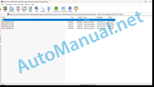
00 0288 768 4.pdf
00 0301 051 0.pdf
00 0303 482 0.pdf
00 2348 868 0.pdf
00 0288 768 4.pdf:
PICK UP 380PICK UP 300
Table of contents
1 Introduction
1.1 Notes on the manual
1.1.1 Validity of the manual
1.1.2 Information about this Operator’s Manual
1.1.3 Symbols and notes
1.1.4 Optional equipment
1.1.5 Qualified specialist workshop
1.1.6 Maintenance notes
1.1.7 Warranty notes
1.1.8 Spare parts and technical questions
1.2 Intended use
1.2.1 Intended use
1.2.2 Reasonably foreseeable misuse
2 Safety
2.1 Identifying warnings
2.1.1 Hazard signs
2.1.2 Signal word
2.2 Safety rules
2.2.1 Importance of Operator’s Manual
2.2.2 Observing safety decals and warnings
2.2.3 Requirements for all persons working with the machine
2.2.4 Children in danger
2.2.5 Hazard areas
2.2.6 Standing between machine and front attachment
2.2.7 Fitting a front attachment or hitching a transport trailer to the machine
2.2.8 Danger of injury from rotating shafts
2.2.9 Structural alterations
2.2.10 Optional equipment and spare parts
2.2.11 Control of the machine while it is running
2.2.12 Only use once properly put into operation
2.2.13 Technical condition
2.2.14 Danger from damage to the machine
2.2.15 Complying with technical limit values
2.2.16 Danger from continued running of machine parts
2.2.17 Keeping safety devices functional
2.2.18 Personal protective equipment
2.2.19 Wearing suitable clothing
2.2.20 Removing dirt and loose objects
2.2.21 Preparing the machine for road travel
2.2.22 Hazards when driving on the road and on the field
2.2.23 Parking the machine safely
2.2.24 Unsuitable operating utilities
2.2.25 Safe handling of operating and auxiliary utilities
2.2.26 Environmental protection and disposal
2.2.27 Avoiding fires
2.2.28 Electrocution by electrical system
2.2.29 Pressurised fluids
2.2.30 Hot surfaces
2.2.31 Working on machine only after shutting it down
2.2.32 Maintenance operations and repair work
2.2.33 Raised machine parts and loads
2.2.34 Hazard from welding work
2.3 Safety decals on the machine
2.3.1 Structure of safety decals
2.3.2 Safety decals on the machine
3 Machine description
3.1 Overview and method of operation
3.1.1 PICK-UP 380 overview
3.1.2 PICK UP 300 overview
3.1.3 Overview of drives
3.1.4 Function of machine
3.2 Optional equipment
3.2.1 Hydraulic auger lift*
3.2.2 Speed reduction unit*
3.2.3 Intake auger tension spring*
3.2.4 Intake paddle extension*
3.2.5 Hydraulic touch wheels*
3.2.6 Spare wheel 18.5×8.5-8*
3.2.7 Centre touch wheel*
3.2.8 ACTIVE CONTOUR*
3.2.9 Acoustic protective cover*
3.3 Identification plates and vehicle identification number
3.3.1 Machine identification plate
3.4 Information on the machine
3.4.1 Stickers on the machine
4 Operating and display elements
4.1 Gearbox
4.1.1 Shifting transfer gearbox*
4.2 Fitting frame
4.2.1 Lever locking device
4.2.2 Pendulum frame lock*
4.2.3 Adjusting aid
4.2.4 Stand
5 Technical specifications
5.1 PICK UP 380
5.1.1 Approved machines
5.1.2 Approved machines
5.1.3 Dimensions
5.1.4 Weights
5.1.5 Tyre dimension
5.1.6 Tyre pressure
5.1.7 Noise level
5.1.8 Lubricants
5.2 PICK UP 300
5.2.1 Approved machines
5.2.2 Approved machines
5.2.3 Dimensions
5.2.4 Weights
5.2.5 Tyres
5.2.6 Tyre pressure
5.2.7 Noise level
5.2.8 Lubricants
6 Machine preparation
6.1 Switching off and securing the machine
6.1.1 Switching off and securing the machine
6.1.2 Securing the raised front attachment
6.2 Mounting the front attachment
6.2.1 Connecting the hydraulic hose lines*
Preparing for attachment
Attaching the machine
6.2.2 Opening the locking device
6.2.3 Fitting the front attachment
6.2.4 Closing the locking device
6.2.5 Adjusting the locking device
6.2.6 Adjusting the locking linkage
6.2.7 Raising the stands
Left stand
Right stand
6.2.8 Connecting the hydraulic hose lines
6.2.9 Connecting the power supply
6.3 Adjusting the front attachment
6.3.1 Checking the dog clutch
6.3.2 Adjusting the dog clutch
Centring the dog clutch
Adjusting the distance
6.3.3 Adjusting the working position
6.4 Removing the front attachment
6.4.1 Extending the stands
Left stand
Right stand
6.4.2 Disconnecting the hydraulic hoses
6.4.3 Disconnecting the hydraulic hoses
6.4.4 Disconnecting the power supply
6.4.5 Locking the pendulum frame
6.4.6 Opening the locking device
6.4.7 Unhitching the front attachment
6.5 Prepare road travel
6.5.1 Folding the dust cover down
6.5.2 Locking the pendulum frame
6.5.3 Swinging the touch wheels to the transport position
6.5.4 Swinging the touch wheels to the transport position
6.6 Preparing fieldwork
6.6.1 Unlocking the pendulum frame
6.6.2 Swinging the touch wheels to the working position
6.6.3 Swinging the touch wheels to the working position
6.6.4 Adapt the centre touch wheel to the tyres
6.7 Loading the front attachment
6.7.1 Raising the front attachment
7 Operation
7.1 Driving on the road
7.1.1 Driving on public roads
7.2 Fieldwork settings
7.2.1 Adjusting the cutting height control on the forage harvester
7.2.2 Setting the working height
7.2.3 Adapting the length of cut
7.2.4 Adapting the length of cut
Selecting the sprocket pair
7.2.5 Adjusting the clearance from the intake auger to the trough
7.2.6 Adjusting the intake auger tension spring
7.2.7 Changing the sprockets
7.2.8 Adjusting the length of cut
7.2.9 Adjusting the pick-up
7.3 Fieldwork
7.3.1 Using the front attachment
7.3.2 Switching on the front attachment
7.3.3 Raising and lowering the front attachment
7.3.4 Raising and lowering the roller crop press
7.3.5 Automatic mode for first variable front attachment drive and second variable front attachment drive
Description of automatic mode of VVA1 on PICK-UP with VVA2
Description of automatic mode of VVA2
Manual adaptation of basic speeds of VVA1 and VVA2
7.3.6 Engaging and disengaging cutting height control
7.3.7 Switching ACTIVE CONTOUR* on and off
Switching ACTIVE CONTOUR on
Switching ACTIVE CONTOUR off
7.3.8 Reversing the front attachment
7.3.9 Disengaging the front attachment
8 Faults and remedies
8.1 Overview of problems
8.1.1 Overview of problems on the machine
8.2 Electric system
8.2.1 Flashing light* defective
9 Maintenance
9.1 Maintenance interval overview
9.1.1 Before the harvest
9.1.2 After the first 10 operating hours
9.1.3 Every 8 operating hours or daily
9.1.4 Every 50 operating hours
9.1.5 Every 250 operating hours
9.1.6 Every 500 operating hours or annually
9.1.7 After the harvest
9.2 Gearbox
9.2.1 Checking the gearbox for leaks
9.2.2 Check the oil level in the main gearbox
9.2.3 Change the oil in the main gearbox
Draining oil
Topping up oil
9.2.4 Checking the oil level in the transfer gearbox
9.2.5 Changing the oil in the transfer gearbox
Draining oil
Topping up oil
9.3 Clutch
9.3.1 Checking the overload clutch
9.3.2 Checking the pick-up overload clutch
9.3.3 Checking the friction discs
9.4 Hydraulic system
9.4.1 Checking the hydraulic hoses
9.4.2 Checking the oil reservoir
9.5 Crop feeding
9.5.1 Check the tyre pressure
9.6 Feeder unit
9.6.1 Checking the drive chain
9.6.2 Checking the intake auger drive chain
9.6.3 Checking the pick up drive chain
9.6.4 Checking the intake auger scraper
9.6.5 Checking the intake auger tension spring*
9.7 Assembly parts and machine body
9.7.1 Removing crop residues
9.7.2 Cleaning the front attachment
9.7.3 Applying preservative to the front attachment
9.7.4 Check the fittings
9.7.5 Adjusting the pendulum frame tension spring
9.8 Lubrication plan
9.8.1 Grease all grease points every 50 operating hours
9.8.2 Grease the lubrication points every 250 operating hours
10 Putting out of operation and disposal
10.1 General information
10.1.1 Removal from service and disposal
11 Declaration of Conformity
11.1 PICK UP 380 / 300
11.1.1 UK declaration of conformity
11.1.2 EC Declaration of Conformity
12 Technical terms and abbreviations
12.1 Terms and explanations
12.1.1 Technical terms
12.1.2 Abbreviations
00 0301 051 0.pdf:
PROFI CAM 3
Table of contents
1 Introduction
1.1 Notes on the manual
1.1.1 Validity of manual
1.1.2 Information about this Operator’s Manual
1.1.3 Symbols and notes
1.1.4 Optional equipment
1.1.5 Qualified specialist workshop
1.1.6 Maintenance information
1.1.7 Warranty notes
1.1.8 Spare parts and technical questions
1.2 Intended use
1.2.1 Intended use
1.2.2 Reasonably foreseeable misuse
2 Safety
2.1 Identifying warnings
2.1.1 Hazard signs
2.1.2 Signal word
2.2 Safety rules
2.2.1 Meaning of Operator’s Manual
2.2.2 Observing safety decals and warnings
2.2.3 Optional equipment and spare parts
3 Product description
3.1 Overview and method of operation
3.1.1 How the PROFI CAM works
3.2 Identification plates and identification number
3.2.1 Position of identification plates
3.2.2 Explanation of PROFI CAM identification plate
3.3 Information on the product
3.3.1 CE marking
4 Operating and control elements
4.1 Camera system
4.1.1 Camera system monitor
4.2 Menu structure
4.2.1 Main menu
4.2.2
4.2.3
4.2.4
4.2.5
4.2.6
5 Technical specifications
5.1 PROFI CAM
5.1.1 Monitor
5.1.2 Camera
5.1.3 Switch box
5.1.4 Degree of protection against foreign bodies and water
6 Preparing the product
6.1 Shutting down and securing the machine
6.1.1 Switching off and securing the machine
6.2 Prior to operation
6.2.1 Carry out prior to operation
6.2.2 Installing the sun protection
6.2.3 Aligning the camera
6.2.4 Connecting the camera electrics
7 Operation
7.1 Monitor
7.1.1 Switching on the monitor
7.1.2 Calling up the menu
7.1.3 Setting a menu item
7.1.4 Setting the image orientation
7.1.5 Setting automatic screen darkening
7.1.6 Image mirroring
7.1.7 Setting the trigger view
7.1.8 Setting the follow-up time for trigger view
7.1.9 Setting the display mode
7.1.10 Activating/deactivating a display mode
8 Faults and remedies
8.1 Electrical and electronic system
8.1.1 Overview of problems on PROFI CAM camera system
8.1.2 Replacing the switch box fuse
9 Maintenance
9.1 Maintenance intervals
9.1.1 Every 10 operating hours or daily
9.2 Camera system
9.2.1 Checking the camera system for dirt
9.2.2 Cleaning the camera
9.2.3 Cleaning the switch box
9.2.4 Cleaning the monitor
10 Placing out of operation and disposal
10.1 General Information
10.1.1 Putting out of operation and disposal
11 Technical terms and abbreviations
11.1 Abbreviations
11.1.1 Units
11.1.2 Abbreviations
11.1.3 Technical terms
00 0303 482 0.pdf:
PROFI CAM 4
Table of contents
1 Introduction
1.1 Notes on the manual
1.1.1 Validity of manual
1.1.2 Information about this Operator’s Manual
1.1.3 Symbols and notes
1.1.4 Optional equipment
1.1.5 Qualified specialist workshop
1.1.6 Maintenance information
1.1.7 Notes on warranty
1.1.8 Spare parts and technical questions
1.2 Intended use
1.2.1 Intended use
1.2.2 Reasonably foreseeable misuse
2 Safety
2.1 Identifying warnings
2.1.1 Hazard signs
2.1.2 Signal word
2.2 Safety rules
2.2.1 Meaning of Operator’s Manual
2.2.2 Structural changes
2.2.3 Optional equipment and spare parts
2.2.4 Operation only following proper putting into operation
2.2.5 Technical status
2.2.6 Respecting technical limit values
Respecting technical limit values
2.2.7 Hazards when driving on roads and fields
3 Product description
3.1 Overview and method of operation
3.1.1 How the PROFI CAM works
3.2 Identification plates and identification number
3.2.1 Identification plates
3.3 Information on the product
3.3.1 CE marking
4 Operating and display elements
4.1 Camera system
4.1.1 Camera system monitor
4.1.2 CEBIS
4.2 Menu structure
4.2.1 Main menu
4.2.2
4.2.3
4.2.4
4.2.5
4.2.6
5 Technical specifications
5.1 PROFI CAM
5.1.1 Monitor
5.1.2 Camera
5.1.3 Switch box
6 Preparing the product
6.1 Switching off and securing the machine
6.1.1 Switching off and securing the machine
6.2 Prior to putting into operation
6.2.1 Carry out prior to operation
6.2.2 Installing the sun protection
6.2.3 Aligning the camera
7 Operation
7.1 Monitor
7.1.1 Switching on the monitor
7.1.2 Calling up the menu
7.1.3 Setting a menu item
7.1.4 Setting the image orientation
7.1.5 Setting automatic screen darkening
7.1.6 Image mirroring
7.1.7 Setting the trigger view
7.1.8 Setting the follow-up time for trigger view
7.1.9 Setting the display mode
7.1.10 Activating/deactivating a display mode
8 Faults and remedies
8.1 Electric and electronic system
8.1.1 Overview of problems on PROFI CAM camera system
9 Maintenance
9.1 Maintenance intervals
9.1.1 Every 10 operating hours or daily
9.2 Camera system
9.2.1 Checking the camera system for dirt
9.2.2 Cleaning the camera
9.2.3 Cleaning the switch box
9.2.4 Cleaning the monitor
10 Putting out of operation and disposal
10.1 General information
10.1.1 Putting out of operation and disposal
11 Technical terms and abbreviations
11.1 Abbreviations
11.1.1 Units
11.1.2 Abbreviations
11.1.3 Technical terms
00 2348 868 0.pdf:
PICK UP 380PICK UP 300
Table of contents
1 To this Operator’s Manual
1.1 Notes on the manual
1.1.1 Validity of the manual
2 Technical specifications
2.1 PICK UP 380 / 300
2.1.1 Approved machines
3 Machine preparation
3.1 Mounting the front attachment
3.1.1 Connecting the hydraulic hose lines*
Preparing for attachment
Attaching the machine
3.2 Removing the front attachment
3.2.1 Disconnecting the hydraulic hoses
4 Maintenance
4.1 Maintenance interval overview
4.1.1 Before the harvest
4.2 Hydraulic system
4.2.1 Checking the oil reservoir
John Deere Repair Technical Manual PDF
John Deere PowerTech M 10.5 L and 12.5 L Diesel Engines COMPONENT TECHNICAL MANUAL CTM100 10MAY11
John Deere Repair Technical Manual PDF
John Deere Diesel Engines PowerTech 4.5L and 6.8L – Motor Base Technical Manual 07MAY08 Portuguese
John Deere Repair Technical Manual PDF
John Deere Repair Technical Manual PDF
John Deere Parts Catalog PDF
John Deere Harvesters 8500 and 8700 Parts Catalog CPCQ24910 Spanish
John Deere Repair Technical Manual PDF
John Deere Repair Technical Manual PDF
John Deere Repair Technical Manual PDF
John Deere DF Series 150 and 250 Transmissions (ANALOG) Component Technical Manual CTM147 05JUN98
John Deere Repair Technical Manual PDF

