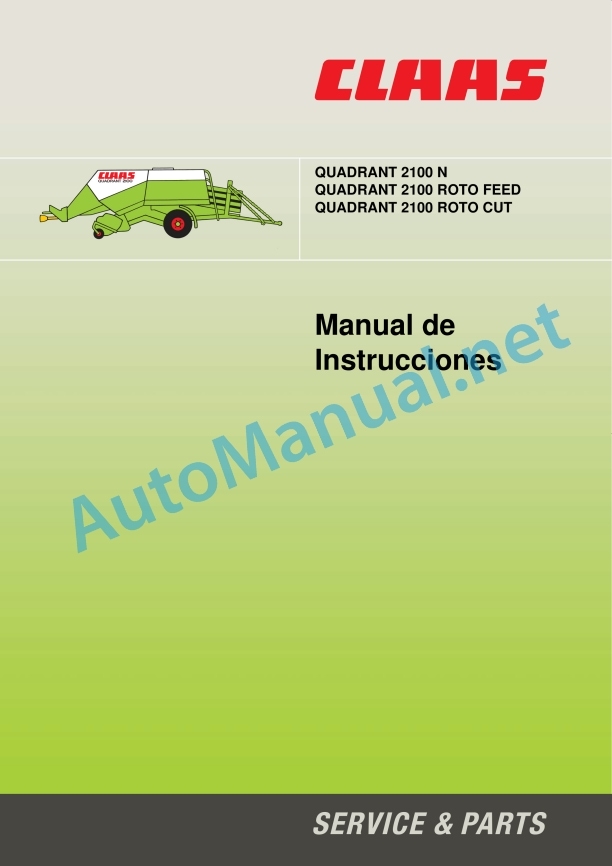
Claas Quadrant 2100 Rc Rf (741) Baler Operator Manual ES
$50.00
- Model: Quadrant 2100 Rc Rf (741) Baler
- Type Of Manual: Operator Manual
- Language: ES
- Format: PDF(s)
- Size: 7.6 MB
File List:
00 0299 055 4.pdf
00 0299 055 4.pdf:
Introduction
Introduction
General indications
road traffic
Important note
Type plate / Serial number
Rating plate
Machine serial number
Security measures
Security measures
Characterization of warning and danger indications
Proper use of the machine
General rules relating to safety and accident prevention
Hooked machines
Power take-off operation (for power take-off driven machines only)
Hydraulic system
Wheels / tires
Maintenance
noise emission; information _x0011_»D«
Hydraulic emergency brake
Operating mode
Safety stickers with graphic danger symbols_x0011_
Technical data
CLAAS Quadrant 2100_x0011_N / 2100_x0011_RF / 2100_x0011_RC
CLAAS Quadrant 2100_x0011_N / 2100_x0011_RF / 2100_x0011_RC
Safety devices
Construction and mode of operation
General view of the machines
Force transmission
Freewheel frictutch
Flywheel brake, mechanical
pickup dr Roller holder (QUADRANT 2100_x0011_RF/RC)
Retaining plate (QUADRANT 2100_x0011_N)
Cutting device (QUADRANT 2100_x0011_RC)
Carrier drive
Rotor drive (QUADRANT 2100_x0011_RF/RC)
Pressing plunger and pressing duct
Humidity sensor (option only on 2100_x0011_RF/RC)
Pressing pressure regulation
Tying mechanism
Knotter Cleaning Installation
Turbo blower
Two-component bale slide (QUADRANT_x0011_2100_x0011_N)
Split unloading ramp (QUADRANT 2100 N)
Hydraulic bale slide (QUADRANT_x0011_2100_x0011_RF/RC)
Bale discharge sensor (option for QUADRANT_x0011_2100_x0011_RF/RC)
Bale ejector (option)
Two-way valve (QUADRANT 2100_x0011_N)
Two-way valve (QUADRANT 2100_x0011_RF/RC)
Central lubrication installation
Central lubrication installation with automatic pump (Option for QUADRANT_x0011_2100_x0011_RF/RC)
Articulated tandem axle (option)
Before start-up
Check and observe before first start-up
Hook up the baler
Regulate the universal lance
Adjust the hitch eye
Change the traction lance from a coupling mouth to a traction pendulum or vice versa
Spear model for USA
Adjust the hitch eye
Adjust the height of the hooking eye (with rotating eye)
Hydraulic connections on the tractor
QUADRANT_x0011_2100_x0011_N
QUADRANT_x0011_2100_x0011_RF/RC
Tractor with hydraulic system with constant performance or Load-Sensing system without Power-Beyond
Tractor with hydraulic system with constant pressure
Tractor with Load Sensing and a Power-Beyond pressure connection
Pick up the kickstand
Install the drive shaft
Install the drive shaft on the machine side
Install the drive shaft on the tractor side
Turning range and clearance
Reduce driveshaft
Reassemble the tube profile device for lubrication
Modification measures (Inner protective tube / outer tube profile – on the machine side…
Modification measures (Intermediate protection support)
Modification measures (Outer protection tube – tractor side)
Secure the cardan shafts in the protective cone against simultaneous rotation
Compressed air brake
Maneuvering the baler without compressed air brake
Hydraulically actuated brake
Electric system
Central electrical system (QUADRANT 2100 RF/RC)
12 Volt Plug
Equipment
Bale slide (QUADRANT 2100_x0011_N)
Lock the bale slide
Hydraulic bale slide (QUADRANT_x0011_2100_x0011_RF/RC)
Pickup support wheels
Before transportation
Baler adjustment
Pickup height adjustment
Adjust the working height of the pickup
Pickup with training wheels
Support wheels
Retainer with retaining plate (QUADRANT_x0011_2100_x0011_N)
Roller retainer adjustment (QUADRANT_x0011_2100_x0011_RF/RC)
Cutting device (QUADRANT 2100_x0011_RC)
Shield blade holder (option)
Adjusting the two-component bale chute (QUADRANT_x0011_2100_x0011_N)
Split discharge ramp adjustment
Adjusting the hydraulic bale slide (QUADRANT 2100_x0011_RF/RC)
yarn drawer
Thread the tying thread
Adjust the thread guide
Start up
Guidance values for ing the pressing pressure
Freewheel friction clutch
Collector overload
Carrier overload (QUADRANT_x0011_2100_x0011_RF/RC)
Rotor overload
Electrical indication of lack of thread
Bale ejector (option)
Hydraulic bale slide (QUADRANT_x0011_2100_x0011_RF/RC)
Adjust bale length (QUADRANT 2100_x0011_N)
Reset the bale counter to zero (QUADRANT_x0011_2100)
Emergency management (QUADRANT_x0011_2100_x0011_RF/RC)
CLAAS COMMUNICATOR
CLAAS COMMUNICATOR – Overview
Claas Communicator-Connection
Synoptic table
Keys and incremental transmitter
Incremental transmitter
Soft keys
Status indication
Work menu
Work menu 1
Work menu 2
Work menu 3
Job Menu Screen
Setting menu
Counteenu
Fault menu
System Information Menu
Settings in the work menu (1)
Adjust bale length
Adjust pressing pressure
Change customer or parcel number
User settings
Call up the setting menu
Adjust bale length
Bale length correction factor
Adjust pressing pressure
Activate the sequence for cleaning the blades
Program the greasing interval (Claas Communicator without and with ISOBUS)
Lubrication with manual control (Claas Communicator with ISOBUS)
Accountants
Call up the counters menu
Select the order
Order reset (position to zero)
Daily counter reset
Maintenance indication reset
Fault indicator
Tying failure (Claas Communicator without ISOBUS)
When starting the Claas communicator
during work
Tying failure (Claas Communicator with ISOBUS)
Tying failure 26
Tying failure 27/28/29
Services Menu
Call service menu
Screen adjustment menu
Adjust screen contrast
Call up the time and date menu
Set the time and date
Call up the memory management menu
Clear memory space
Call up the language selection menu
Adjust the language selection menu
Call up the aux menu.
Operation according to settings
Raise/lower the pickup
Increase/decrease pressing pressure
Manually trigger the tying process
Fold/unfold the blades
Raise/lower cutting frame
Lock/unlock the articulated axle (option)
Manual lubrication control (Claas Communicator with ISOBUS)
After the job
Uncouple the baler
steering wheel brake
wheel chocks
Foot support
Disconnect the hydraulic hoses
Electric cables
Disconnect the compressed air hoses
Deposit the transmission shaft
Cleaning the baler
Body and interior sector of the baler
piston rod
Maintenance
Important maintenance instructions
Important maintenance instructions_x0011_
Maintenance tables
Lubricant table
brake equipment
Compressed air brake
Bleed the air tank
brake cylinders
Adjust the brake lever
Hydraulically actuated brake
brake cylinders
Adjust the brake lever
Check the seat of the wheel nuts
Check the wheel hub bearing clearance
Adjust bearing clearance
Hydraulic system
Oil level check up to machine No. 74100325/74200047
Oil change until machine No. 74100325/74200047
Oil level control from machine No. 74100326/74200048 and all machines with …
Oil change from machine No. 74100326/74200048 and all machines with Turbofan
Clean the hydraulic oil filter up to machine No. 74100325/74200047
Clean the hydraulic oil filter from machine No. 74100326/74200048 and all models.
main gear
Timing gear – pickup / hauler (QUADRANT_x0011_2100_x0011_N)
Timing gear – rotor/carrier drive (QUADRANT_x0011_2100_x0011_RF/RC)
Rotor drive upper gear (QUADRANT_x0011_2100_x0011_RF/RC)
Rotor drive lower gear (QUADRANT_x0011_2100_x0011_RF/RC)
Knotter drive gear
Overload clutches and shear screw
Freewheel friction clutch
Main drive
Pickup drive
Knotting shaft drive
Check binding activation, adjustment (QUADRANT_x0011_2100_x0011_RF/RC)
Drive Chains
Tension the pickup drive chain
Tension the drive chain of the transverse conveyor thread
Adjust the springs for the retaining plates
Adjust the springs for the knotter hooks
Knotter shaft brake
Adjust knotter sprocket clearance
Needle rocker brakes
Basic settings
Adjust the drives according to the markings
Tying mechanism
Adjust the knotting shaft and needles
Check the position of the needles with respect to the plunger
Fine adjustment via knotting drive
Possibility of control in the pressing duct
Plunger lock
Thread presser
Raise the baler
Clear a jam in the baler
Conditions for use to avoid jams
Procedure for clearing a jam
Collector jamming
Auger stuck
Normal jam
Major jam
Carrier jamming
Rotor jamming
Tips for preparing for winter
Central lubrication
Function of central lubrication
Central lubrication with automatic pump (Option for QUADRANT 2100_x0011_RF/RC)
Fill the lubricating grease tank
Fill with grease injector
Fill with charging pump
Filling the grease tank
Central lubrication system with manual lever oiler
Fill manual lever grease nipple with grease
Replace the grease pipes
Install the grease ducts
Greasing scheme
Lubricants and indications
Faults, cause and solution
Faults, cause and solution
Alphabetical index
Alphabetical index
John Deere Repair Technical Manual PDF
John Deere Repair Technical Manual PDF
John Deere 16, 18, 20 and 24HP Onan Engines Component Technical Manual CTM2 (19APR90)
John Deere Repair Technical Manual PDF
John Deere Repair Technical Manual PDF
John Deere Repair Technical Manual PDF
John Deere Diesel Engines PowerTech 4.5L and 6.8L – Motor Base Technical Manual 07MAY08 Portuguese
John Deere Repair Technical Manual PDF
John Deere PowerTech M 10.5 L and 12.5 L Diesel Engines COMPONENT TECHNICAL MANUAL CTM100 10MAY11
John Deere Parts Catalog PDF
John Deere Tractors 6300, 6500, and 6600 Parts Catalog CQ26564 (29SET05) Portuguese
John Deere Parts Catalog PDF
John Deere Tractors 7500 Parts Catalog CPCQ26568 30 Jan 02 Portuguese


