Claas Quadrant 2200 Rc (735) Baler Technical System ES
$150.00
- Model: Quadrant 2200 Rc (735) Baler
- Type Of Manual: Technical System
- Language: ES
- Format: PDF(s)
- Size: 4.9 MB
File List:
00 0299 302 2.pdf
00 0299 303 3.pdf
00 0299 304 2.pdf
00 0299 302 2.pdf:
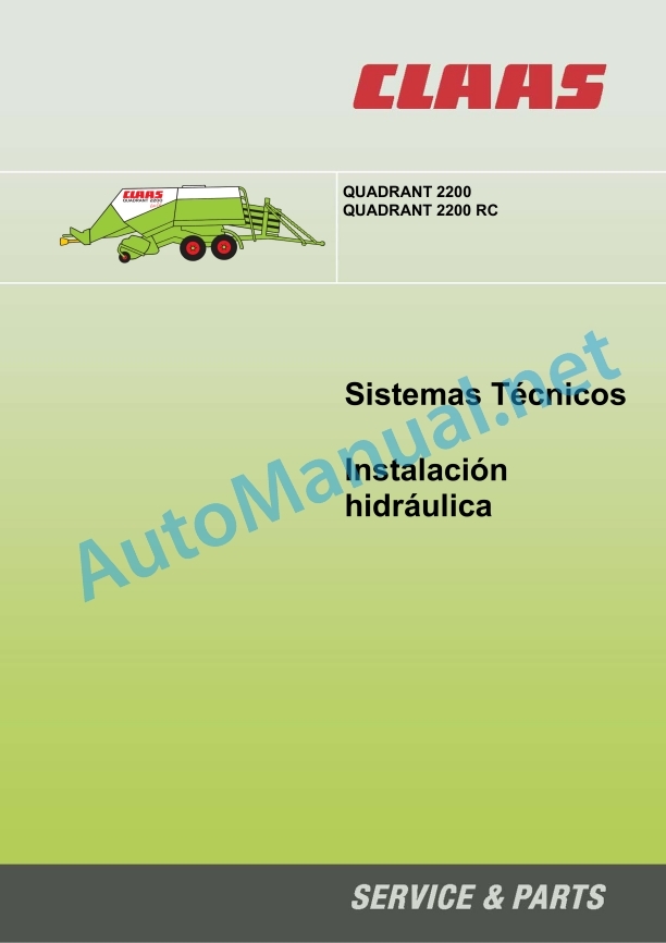
Quadrant 2200 hydraulic installation
1 Quadrant 2200 hydraulic system connection diagram
1.1 Connection diagram of the general hydraulic system Quadrant 2200 – Rotocut up to machine no. 1166; feed rotor to machine no. 1416
1.2 Connection diagram of the general hydraulic system Quadrant 2200 – Rotocut from machine no. 1167, feed rotor from machine no. 1417
2_x000B__x000B_Main valve
2.1 Main valve
2.2 2/2-way valve (pressure pressure overload protection)
2.3 Hydraulic cylinder (pressing channel)
3_x000B__x000B_ROTOCUT blades, cutting bottom
3.1 4/3-way electromagnetic valve blades ROTOCUT CONEC. / OFF, open / close the cutting floor
3.2 Hydraulic cylinder for ROTOCUT blades CONN.
3.3 Hydraulic cylinder open/close the cutting bottom
4_x000B__x000B_Bale ejector
4.1 4/3-way solenoid valve – ROTOCUT bale ejector to machine no. 1166; – feeding rotor tohine nr. 1416
4.2 4/3-way solenoid e – ROTOCUT bale ejector from machine no. 1167; – feed rotor from machine no. 1417
4.3 Hydraulic bale ejector cylinder
5_x000B__x000B_Raise/lower the Pickup
5.1 Pressure limiting valve with pressure retainer (Pickup)
5.2 Hydraulic cylinder raise / lower the Pickup
6 Turbofan (knotter cleaning fan)
6.1 Turbofan hydraulic connection diagram
6.2 Turbofan valve block
7_x000B__x000B_Steering axle lock
7.1 Hydraulic connection diagram
8_x000B__x000B_Row spreader
8.1 Hydraulic connection diagram, row spreader
9_x000B__x000B_Valve elements
9.1 Valve elements in multi-way valves
9.2 Function of valve elements
0299 302.2
00 0299 303 3.pdf:
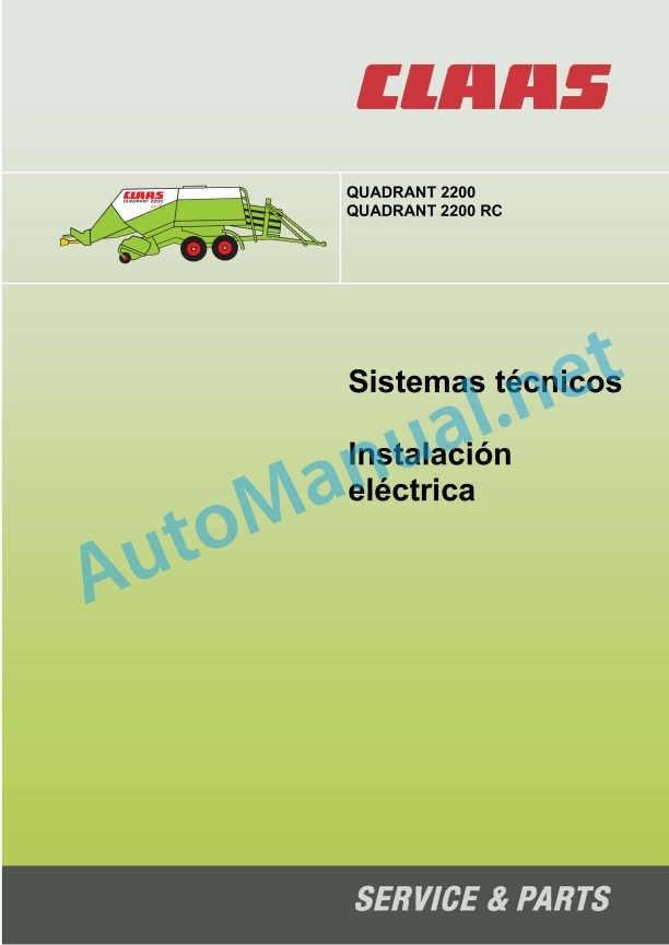
Technical systems – Electrical installation, QUADRANT 2200 / QUADRANT 2200 RC
Assembly of connection diagrams
central electrical system
Central electrical system (4 modules)
CCU – Claas Control Unit (1 module)
Module occupancy
Module A20 -1
Module A20 -2
Module A20 -3
Modul0 -4
A20 CCU module, with A30 CCT terminal
Module A20 – CCU, with A30 Communicator tnal
Module A20 – CCU, with A30 Communicator terminal – with plug-in connections Company Deutsch
Main system power supply voltage 01a – 40c
01a – Power supply to the main voltage system (with central electrical system)
01b – Main voltage system supply (with CCU)
01c – Power supply to the main voltage system (with CCU and Communicator)
01d – Main voltage system supply (with CCU and Communicator), with plug-in connections Company Deutsch
04a – Circulation blocking valve (with central electrical system)
04b – Circulation blocking valve (with CCU)
04c – Circulation Block Valve (with CCU and Communicator, with Company Deutsch plug-in connections)
05a – Terminal (with central electrical system)
05b – Terminal (with CCU and CCT)
06a – CAN-Bus, module voltage supply (with central electrical system)
06b – CAN-Bus, module voltage supply (with CCU and CCT)
06c – CAN-Bus, module voltage supply (with CCU and Communicator)
06d – CAN-Bus, module power supply (with CCU and Communicator, with Company Deutsch plug-in connections)
07a – Rotocut (with central electrical system)
07b – Rotocut (with CCU)
07c – Rotocut (with CCU and Communicator, with Company Deutsch plug-in connections)
08a – Cutting floor automation (with central electrical system, 5 V cutting floor sensor)
08b – Cutting floor automation (with central electrical system, 12 V cutting floor position sensor)
08c – Cutting bottom automation (with CCU and CCT)
08d – Cutting bottom automation (with CCU and Communicator)
08e – Cutting floor automation (with CCU and Communicator, with Company Deutsch plug-in connections)
10a – Regulation of pressing pressure (with central electrical system)
10b – Regulation of pressing pressure (with CCU and CCT)
10c – Regulation of pressing pressure (with CCU and Communicator)
10d – Pressing pressure regulation (with CCU and Communicator, with Company Deutsch plug-in connections)
11a – Activation of tying, cleaning of the knotter (with central electrical system)
11b – Activation of tying, cleaning of the knotter (with central electrical system, with 12 V cutting bottom sensor)
11c – Activation of tying, cleaning of the knotter (with CCU and CCT)
11d – Tying trigger, knotter cleaning (with CCU and Communicator) – until year of manufacture 2005
11e – Tying trigger, knotter cleaning (with CCU and Communicator) – until year of manufacture 2005
11f – Tying trigger, knotter cleaning (with CCU and Communicator, with Company Deutsch plug-in connections), until year of manufacture 2005
13a – Eject the bales (with central electrical system)
13b – Eject the bales (with CCU and CCT)
13c – Eject the bales (with CCU and Communicator)
13d – Ejecting bales (with CCU and Communicator, with Company Deutsch plug-in connections)
26a – Machine control (with central electrical system)
26b – Machine control (with CCU and CCT)
26c – Machine control (with CCU and Communicator)
26d – Machine control (with CCU and Communicator, with Company Deutsch plug-in connections)
27a – Operating instructions (with central electrical system)
27b – Operating indications (with CCU and CCT)
27c – Operational indicators (bale tank, pressing piston load indicator, stem humidity) (with CCU and Communicator)
27d – Operational indicators (with CCU and Communicator, with Company Deutsch plug-in connections)
29a – Central lubrication system (with central electrical system)
29b – Central lubrication system (with CCU)
29c – Central lubrication system (with CCU and Communicator, with Company Deutsch plug-in connections)
32a – Rear light, position light (with central electrical system)
40a – Additional sockets (with central electrical system)
40b – Additional sockets (with CCU)
40c – Additional sockets (with CCU, with Company Deutsch plug-in connections)
cable trunk
Cable trunk A (with central electrical system)
Cable trunk B (with central electrical system)
Cable trunk C – 1st part (with central electrical system)
Cable trunk C – 2nd part (with central electrical system)
Cable trunk C – 3rd part (with central electrical system)
Cable trunk D – 1st part (with central electrical system)
Cable trunk D – 2nd part (with central electrical system)
Cable trunk E (with CCU)
Cable trunk F (with CCU)
G cable trunk (with CCU)
Cable trunk H – 1st part (with CCU)
Cable trunk H – 2nd part (with CCU)
Cable trunk I (with CCU)
Cable trunk K (with Communicator)
Alphabetical index:
0299 303.3
00 0299 304 2.pdf:
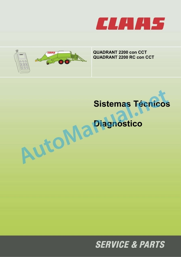
Diagnostics QUADRANT 2200 with CCT / QUADRANT 2200 RC with CCT
1.0 Control terminal maintenance service menu (up to module 1 No. 835024.2)
1.1 Maintenance service menu structure (up to module 1 No. 835024.2)
1.2 Additional information on page 8/1 (maintenance service 1) (up to module 1 No. 835024.2)
1.3 Additional information on page “8/2 (Rotocut RC maintenance service)” (up to module 1 No. 835024.2)
1.4 Verification of inputs (up t 1 no. 835024.2)
1.5 Verification of the outputs (up to module 1 nr. 835024.2)
1.6 Fault in (up to module 1 No. 835024.2)
1.7 Checking pushbuttons (up to module 1 No. 835024.2)
2.0 Maintenance service menu of the control terminal (from module 1 No. 835024.3)
2.1 Structure of the maintenance service menu (as of module 1 No. 835024.3)
2.2 Additional information on page “8/1 (maintenance service 1)” (from module 1 No. 835024.3)
2.3 Additional information on page “8/2 (Rotocut RC maintenance service)” (from module 1 No. 835024.3)
2.4 Verification of inputs (from module 1 no. 835024.3)
2.5 Verification of the outputs (from module 1 no. 835024.3)
2.6 Fault display (from module 1 No. 835024.3)
2.7 Checking pushbuttons (from module 1 No. 835024.3)
3.0 Control Terminal Maintenance Service Menu (with CCU Module)
3.1 Maintenance service menu structure (with CCU module)
3.2 Additional information on page 8/1 (maintenance service 1) (with CCU module)
3.3 Additional information on 2 (Rotocut RC maintenance service)” (with CCU module)
3.4 Verification of inputs (with CCU module)
fication of the outputs (with the CCU module)
3.6 Fault indication (with CCU module)
3.7 Checking pushbuttons (with CCU module)
4.0 Supplementary information
4.1 Check pressing pressure sensor (B56) (with central electrical system)
4.2 Check star wheel / bale length sensor (B69) (with central electrical system)
4.3 General information (with central electrical system)
5.0 Indications related to changing modules
0299 304
John Deere Parts Catalog PDF
John Deere Harvesters 8500 and 8700 Parts Catalog CPCQ24910 Spanish
John Deere Parts Catalog PDF
John Deere Tractors 7500 Parts Catalog CPCQ26568 30 Jan 02 Portuguese
John Deere Repair Technical Manual PDF
John Deere Repair Technical Manual PDF
John Deere Repair Technical Manual PDF
John Deere Repair Technical Manual PDF
John Deere Parts Catalog PDF
John Deere Tractors 6300, 6500, and 6600 Parts Catalog CQ26564 (29SET05) Portuguese
John Deere Repair Technical Manual PDF
John Deere Diesel Engines POWERTECH 2.9 L Component Technical Manual CTM126 Spanish


