Claas Quadrant 3400 (740) Baler Operator Manual ES
$50.00
- Model: Quadrant 3400 (740) Baler
- Type Of Manual: Operator Manual
- Language: ES
- Format: PDF(s)
- Size: 55.5 MB
File List:
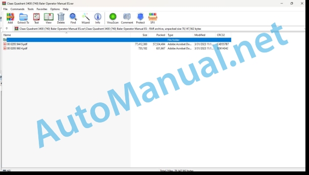
00 0295 944 9.pdf
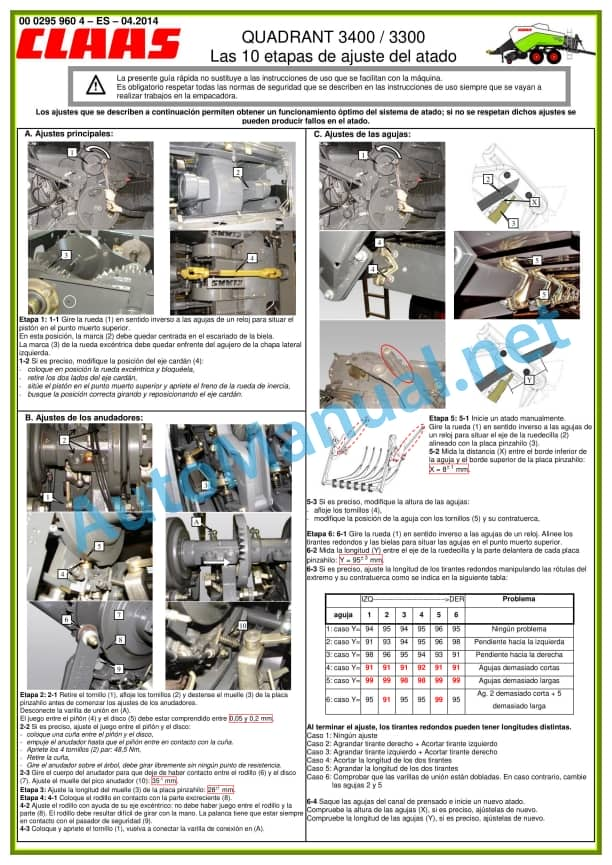
00 0295 960 4.pdf
00 0295 944 9.pdf:
QUADRANT 3400 RotoFeedQUADRANT 3400 RotoCut
1 Regarding this instruction manual
1.1 General data
1.1.1 Application of this manual
1.1.2 About this user manual
1.1.3 Technical characteristics
2 Security
2.1 General data
2.1.1 General information
2.1.2 Authorized use
2.1.3 Reasonably foreseeable misuse
2.1.4 Safety regulations
2.1.5 Symbols applicable to danger indications
2.1.6 Highway driving
2.1.7 Accident prevention
2.1.8 Waste disposal
2.1.9 Residual risks
2.2 Graphic danger symbols
2.2.1 Description
2.2.2 Location of safety stickers
2.3 Safety equipment
2.3.1 Signal lights
2.3.2 Reflective equipment
2.3.3 Surety
2.3.4 Shims
2.3.5 Parking brake
2.3.6 Flywheel brake
2.3.7 Locking the pick-up
2.3.8 Rotating flashing light
3 Machine Description
3.1 Existing models
3.1.1 Designation of machines
3.2 Overview and functions
3.2.1 Left side
3.2.2 Right side
3.3 Work and service positions
3.3.1 General information
3.3.2 Front of the baler
3.3.3 Top of the baler
3.4 Identification plate and serial number
3.4.1 Spare parts and technical information
3.4.2 Position of the nameplates
3.4.3 Machine nameplate
3.4.4 Rudder nameplate
3.5 General operating principle
3.5.1 Bale pressing cycle
3.6 Control terminal
3.6.1 Control terminal
3.6.2 ICT – Implement Controls Tractor
3.6.3 ISOBUS connection
3.7 Transmission and drive
3.7.1 Power transmission
3.7.2 Friction clutch
3.7.3 Main drive
3.7.4 Rotor drive
3.7.5 Carrier drive
3.7.6 Knotter operation
3.8 Reception of the harvest
3.8.1 Pick-up
3.8.2 Reducing rollers
3.9 Power set
3.9.1 Rotor
3.9.2 RotoCut cutting device (optional)
3.9.3 Pre-chamber
3.9.4 Carrier
3.10 Pressing system
3.10.1 Piston and pressing channel
3.11 Tying system
3.11.1 Tying process
3.11.2 Thread boxes
3.11.3 Thread shortage indicator
3.11.4 Needles
3.11.5 Knotters
3.11.6 Turbofan
3.11.7 Compressed air cleaning device (optional)
3.12 Unloading bales
3.12.1 Two-way key
3.12.2 Bale exit ramp
3.12.3 Bale unloading ramp position detector
3.12.4 Bale unloading sensor (optional)
3.12.5 Humidity sensor (optional)
3.12.6 Bale ejector
3.13 Centralized lubrication
3.13.1 Automatic centralized lubrication
3.13.2 Supplemental lubrication
3.14 Axis
3.14.1 General information
3.14.2 Bogie axle
3.14.3 Follower bogie axle
3.15 Service brake
3.15.1 General information
3.15.2 Pneumatic braking
3.15.3 Hydraulic braking
3.15.4 Active hydraulic braking
3.16 Hydraulic system
3.16.1 Hydraulic oil tank
3.16.2 Load Sensing
3.17 Equipment
3.17.1 Ladder
3.17.2 Front ladder support
3.17.3 Storage cabinet (optional)
3.17.4 Electronic module
3.17.5 12 V socket
4 Control and display instruments
4.1 CLAAS COMMUNICATOR
4.1.1 Presentation
4.1.2 Description of the CLAAS COMMUNICATOR Using menus
4.2 CLAAS OPERATOR
4.2.1 Presentation
4.3 ISOBUS Terminal
4.3.1 Presentation
4.3.2 General information
5 Technical data
5.1 Baler
5.1.1 General information
5.1.2 Dimensions
5.1.3 Weight
5.1.4 Hooking
5.1.5 Cardan shaft
5.1.6 Feeding and pressing
5.1.7 Tying device
5.1.8 Wheels
5.1.9 Braking
5.1.10 Hydraulic circuit
5.1.11 Greasing and lubrication
5.1.12 Screw tightening torques
5.1.13 Sound levels
5.2 Safety devices
5.2.1 Security screw
5.2.2 Overload safety
5.3 Tractor
5.3.1 Required power
5.3.2 PTO
5.3.3 Hookup
5.3.4 Electrical connections
5.3.5 Hydraulic connections
5.3.6 Hydraulic circuit and oil
5.3.7 Braking
6 Preparation of the machine
6.1 General data
6.1.1 First commissioning
6.1.2 Equipment control
6.2 Cardan shaft
6.2.1 Safety regulations
6.2.2 Cardan shaft adjustment
6.2.3 Adaptation of the cardan shaft length
6.2.4 Double-joint wide-angle gimbal
6.2.5 Placing the cardan shaft
6.3 Trailer support
6.3.1 Recommendations
6.3.2 Types of fixing
6.3.3 Hitch fixing
6.3.4 Adaptation of the fork hitch/oscillating bar hitch
6.3.5 Hitching the baler to the tractor
6.3.6 Positioning the cardan shaft
6.4 Hydraulic connections
6.4.1 Location of flexible ducts
6.4.2 Sear and pick-up
6.4.3 Tractor with Load-Sensing hydraulic system with Power Beyond intake
6.4.4 Tractor with constant flow hydraulic system and Tractor with Load-Sensing hydraulic system without Power Beyond
6.4.5 Tractor with constant pressure hydraulic system
6.4.6 Follower bogie axle (optional)
6.5 Electrical connections
6.5.1 Marking of electrical cables
6.5.2 Lights
6.5.3 Battery cable (optional)
6.5.4 Power supply to the baler and CLAAS COMMUNICATOR
6.5.5 Power supply to the baler and CLAAS COMMUNICATOR – Baler equipped with the TELEMATICS on Implement option
6.5.6 Baler power supply with ISOBUS cable
6.6 Service brake
6.6.1 Hydraulic brake
6.6.2 Active hydraulic brake
6.6.3 Air brake
6.7 Tied
6.7.1 Yarn quality
6.7.2 Preparation
6.7.3 Thread tensioner adjustment
6.7.4 Thread placement
6.7.5 Placing the thread in the knotters
6.7.6 Checking the settings
6.8 Cutting device
6.8.1 Safety regulations
6.8.2 Control
6.8.3 Placing the blades
6.8.4 Assembly of false blades (optional)
6.8.5 Unused blades and dummy blades
6.9 Machine loading
6.9.1 Lifting the baler
6.9.2 Baler stowage
7 Management
7.1 General data
7.1.1 Baler user
7.1.2 Opening doors and casings
7.2 Movements with the baler
7.2.1 Equipment control
7.2.2 Preparations for transportation
7.2.3 Road travel
7.2.4 Arrival at the field
7.2.5 Moving around the field
7.2.6 Parking
7.3 Before each use
7.3.1 Reminders
7.3.2 Cardan shaft
7.3.3 Baler maintenance
7.4 Commissioning in the field
7.4.1 Usage tips
7.4.2 Commissioning of the machine
cardan shaft
Material transfer system
After a machine stop
7.4.3 Bale exit ramp
7.4.4 Bale ejector
7.4.5 Tracking axis (optional)
7.5 Pick-up
7.5.1 Important
7.5.2 Oscillating pick-up wheels
7.5.3 Foldable pick-up wheels
7.5.4 Pick-up height
7.5.5 Reducing rollers
7.6 Cutting device
7.6.1 RotoCut cutting device (optional)
7.7 Bale parameters
7.7.1 Bale adjustments
7.8 CLAAS COMMUNICATOR
7.8.1 Pressing process
7.8.2 Pressing pressure (RotoCut option)
7.8.3 Bale length
7.8.4 Pre-chamber retention force
7.8.5 Carrier loading
7.8.6 Material transfer system
7.8.7 Cutting device (optional)
7.8.8 Selection of the number of blades
7.8.9 Automatic cleaning of the blades (depending on equipment)
7.8.10 Cutting frame
7.8.11 Pressing channel filling indicator (optional)
7.8.12 Manual activation of the tying process
7.8.13 Automatic lubrication
7.8.14 Pick-up rotation speed
7.8.15 Counters Menu
Maintenance indicator reset
7.8.16 Selection of the work
7.8.17 Name of the work
7.8.18 Print client or project data
7.8.19 TELEMATICS on Implement (optional)
7.8.20 Task management (optional)
7.8.21 Faults
7.8.22 ICT – Interface Status
7.8.23 ICT CRUISE PILOT (option)
7.8.24 ICT Auto PTO Stop (option)
7.8.25 ICT Camera (option)
7.8.26 Functions assignable to programmable keys
7.9 Unclogging the baler
7.9.1 How to avoid traffic jams?
7.9.2 Safety regulations
7.9.3 Pick-up jam
7.9.4 Rotor jam
7.10 After use
7.10.1 Reminders
7.10.2 Baler protection
7.10.3 Disconnecting the baler
7.10.4 Daily checks
7.10.5 Daily cleaning
8 Incident and solution
8.1 Tied
8.1.1 Origin of tying problems
8.1.2 Resolution of tying problems
8.2 Centralized lubrication
8.2.1 Resolution of centralized lubrication problems
8.3 Control terminal
8.3.1 Faults displayed on the control terminal
8.3.2 Main drive and system
8.3.3 Transfer system
8.3.4 Hydraulic system
8.3.5 Bale exit ramp
8.3.6 Lack of thread
8.3.7 Tying failures
8.3.8 ICT faults – CRUISE PILOT
8.3.9 ICT Failures – Auto PTO Stop
8.4 Electrical/electronic installation
8.4.1 Electrical circuit
9 Maintenance
9.1 General maintenance instructions
9.1.1 Maintenance and safety tips
9.1.2 Wheels and tires
9.1.3 Brakes
9.1.4 Hydraulic circuit
9.1.5 V-belts
9.1.6 Chains
9.1.7 Pressing and tying device
9.1.8 Cardan shaft
9.1.9 Hitch
9.1.10 Cutting device
9.1.11 Protection devices
9.1.12 Screws and nuts
9.1.13 Lubrication and greasing
9.1.14 Inductive sensors
9.1.15 Welding work
9.1.16 Spare parts
9.2 Lubricant tables
9.2.1 Lubricants
9.3 Maintenance tables
9.3.1 Maintenance operations before harvest
9.3.2 Maintenance operations after the first 10 hours of service
9.3.3 Maintenance operations after the first 50 hours of service
9.3.4 Maintenance operations after the first 100 hours of service
9.3.5 Maintenance operations after the first 250 hours of service
9.3.6 Maintenance operations every 10 hours of service or every day
9.3.7 Maintenance operations every 50 hours of service
9.3.8 Maintenance operations every 100 hours of service
9.3.9 Maintenance operations every 250 hours of service
9.3.10 Maintenance operations every 500 hours of service
9.3.11 Maintenance operations every 15,000 bales
9.3.12 Maintenance operations if necessary
9.4 Basic operations
9.4.1 Manual operation of the machine
9.4.2 Pressing piston at the front dead center
9.4.3 Start tying manually
9.5 Basic settings
9.5.1 Basic baler settings
Machine adjustment control
Knotter shaft adjustment
Carrier Drive Cylinder Drive Adjustment
Adjusting the knob of the round needle straps
Adjusting the flat needle shoulder strap knob
Carrier shaft adjustment
Carrier Adjustment
9.5.2 Carrier Adjustment
9.5.3 Command and position of the carrier
Carrier control levers
Adjusting the hauler control levers
Carrier position
Carrier position adjustment
9.5.4 Carrier control cylinder
Carrier control cylinder control
Adjust the carrier control cylinder
9.5.5 Sensors
9.5.6 Counterblades
9.5.7 Carrying drive box stop adjustment
9.6 Gear maintenance operations
9.6.1 Main box
9.6.2 Fixing the main drive box
9.6.3 Rudder angle transmission box
9.6.4 Rotor drive box
9.6.5 Carrier drive box
9.6.6 Knotter drive box
9.6.7 V-belts
9.6.8 Flywheel brake
9.7 Maintenance operations on the clutch
9.7.1 Friction clutch
9.7.2 Main drive security screw
9.7.3 Carrier drive safety screw
9.7.4 Carrier drive through screw
9.7.5 Knotter shaft drive safety screw
9.8 Axle and wheel maintenance operations
9.8.1 Bogie axle
9.8.2 Follower bogie axle
9.8.3 Wheel tightening check
9.8.4 Replacing the wheels
9.8.5 Wheel hubs
9.8.6 Tire check
9.9 Brake maintenance operations
9.9.1 Hydraulic and active hydraulic braking
9.9.2 Pneumatic braking
9.9.3 Replacing the brake linings
9.10 Hydraulic system maintenance operations
9.10.1 Hydraulic tank
9.10.2 Protection against pressure overloads
9.10.3 Hydraulic pressure accumulator
9.11 Pick-up maintenance operations
9.11.1 Pick-up
9.12 Tying maintenance operations
9.12.1 Needles
9.12.2 Replacing the needle brake plates
Remove a needle brake
Disassembling a needle brake
Install a needle brake
Install a needle brake
9.12.3 Thread tensioner adjustment
9.12.4 Needle hole adjustment
9.12.5 Knotter settings
9.12.6 Tying trigger adjustment
9.12.7 Replacing the knotter brake plates
Remove the brake from the knotters
Remove the brake from the knotters
Install the knotter brake
Install the knotter brake
9.12.8 Turbofan
9.12.9 Knotter cleaning device (complementary kit)
9.12.10 Knotter cleaning device air tank
9.13 Hitch device maintenance operations
9.13.1 Checking the attachment hole fixation
9.13.2 Checking the rudder head fixation
9.14 Maintenance operations of the centralized lubrication system
9.14.1 Automatic centralized lubrication
9.15 Greasing scheme
9.15.1 Greasing intervals
9.15.2 Cardan shaft
9.15.3 Greasing points – 10 h
9.15.4 Greasing points – 50 h
9.15.5 Greasing points – 100 h
9.16 Hibernation
9.16.1 General information
9.16.2 Cleaning
9.16.3 Greasing
9.16.4 Maintenance
9.16.5 Storage
10 Decommissioning and waste disposal
10.1 General data
10.1.1 Decommissioning and waste disposal
11 EC declaration of conformity
11.1 General data
11.1.1 Declaration of conformity for CE
11.1.2 Declaration of conformity for CE
John Deere Repair Technical Manual PDF
John Deere POWERTECH E 4.5 and 6.8 L Diesel Engines TECHNICAL MANUAL 25JAN08
John Deere Parts Catalog PDF
John Deere Harvesters 8500 and 8700 Parts Catalog CPCQ24910 Spanish
John Deere Repair Technical Manual PDF
John Deere Repair Technical Manual PDF
John Deere Repair Technical Manual PDF
John Deere Transmission Control Unit Component Technical Manual CTM157 15JUL05
John Deere Parts Catalog PDF
John Deere Tractors 7500 Parts Catalog CPCQ26568 30 Jan 02 Portuguese
John Deere Repair Technical Manual PDF
John Deere Repair Technical Manual PDF
John Deere Repair Technical Manual PDF
John Deere Diesel Engines POWERTECH 2.9 L Component Technical Manual CTM126 Spanish
John Deere Repair Technical Manual PDF


