Claas Quadrant 5200 (J31) Balers Operator Manual EN
$50.00
- Model: Quadrant 5200 (J31) Balers
- Type Of Manual: Operator Manual
- Language: EN
- Format: PDF(s)
- Size: 317 MB
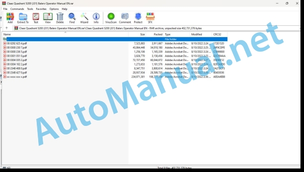
File List:
00 0292 625 4.pdf
00 0300 230 7.pdf
00 0300 236 5.pdf
00 0301 051 0.pdf
00 0304 035 2.pdf
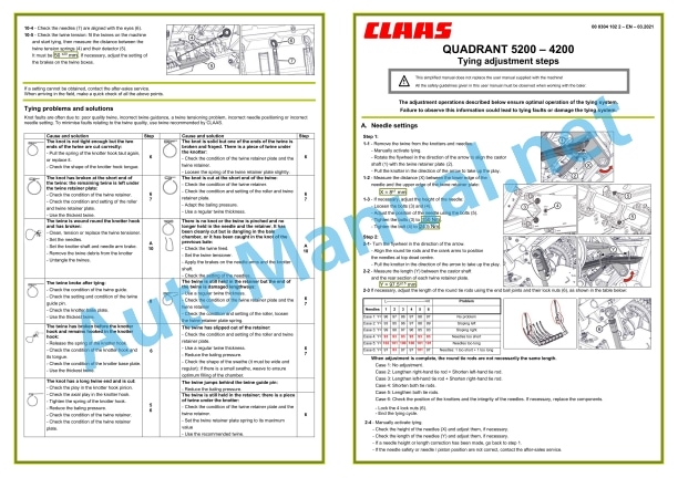
00 0304 102 2.pdf
00 2348 408 0.pdf
00 2348 427 0.pdf
xx xxxx xxx x.pdf
00 0292 625 4.pdf:
COMMUNICATOR II
Table of contents
1 Introduction
1.1 Notes on the manual
1.1.1 Validity of manual
1.1.2 Information about this Operator’s Manual
1.1.3 Symbols and notes
1.1.4 Optional equipment
1.1.5 Qualified specialist workshop
1.1.6 Maintenance notes
1.1.7 Notes on warranty
1.1.8 Spare parts and technical questions
1.2 Intended use
1.2.1 Intended use
1.2.2 Reasonably foreseeable misuse
2.1 Identifying warnings
2.1.1 Hazard signs
2.1.2 Signal word
2.2 Safety rules
2.2.1 Meaning of Operator’s Manual
2.2.2 Requirements made on all persons working with the product
2.2.3 Hazard areas
Hazard areas
2.2.4 Interaction between the control terminal and the machine or tractor
2.2.5 Structural changes
2.2.6 Optional equipment and spare parts
2.2.7 Technical status
2.2.8 Danger from damage to the machine
2.2.9 Complying with technical limit values
2.2.10 Preparing the product for road travel
2.2.11 Hazards when driving on the road and in the field
2.2.12 Hazards when driving on the road with an ISOBUS implement
2.2.13 Switching off the terminal while driving
2.2.14 Electrocution by electrical system
2.2.15 Only carry out work on the machine when it is stopped
2.2.16 Maintenance operations and repair work
2.2.17 Raised machine parts and loads
2.2.18 Welding work prohibited
3 Product description
3.1 Overview and method of operation
3.1.1 Overview of COMMUNICATOR II
3.1.2 Function of COMMUNICATOR II
3.2 Identification plates and identification numbers
3.2.1 Identification plate of COMMUNICATOR II
4 Operating and display elements
4.1 COMMUNICATOR II
4.1.1 Terminal
4.1.2 Terminal program
4.2 Universal terminal menu structure (service)
4.2.1 Main menu of universal terminal
4.2.2
4.2.3
4.2.4
4.2.5
4.3 Job processing (task) menu structure
4.3.1 Job processing main menu
4.3.2
4.3.3
4.3.4
4.3.5
4.3.6
5 Technical specifications
5.1 COMMUNICATOR II
5.1.1 Specification
6 Preparing the product
6.1 Switching off and securing the machine
6.1.1 Shut down and secure the machine
7 Operation
7.1 Switching COMMUNICATOR II on/off
7.1.1 Switching COMMUNICATOR II on
7.1.2 Selecting the application
7.1.3 Switching off COMMUNICATOR II
7.2 Programmable keys
7.2.1 Displaying the key assignment
7.2.2 Creating a key assignment
Step 1: Selecting the control and the key
00 0300 230 7.pdf:
QUADRANT 5200 ROTO FEEDQUADRANT 5200 ROTO CUTQUADRANT 5200 FINE CUT
Table of contents
1 Introduction
1.1 General information
1.1.1 Manual validity
1.1.2 Information about this Operator’s Manual
1.1.3 Symbols and notes
1.1.4 Optional equipment
1.1.5 Qualified specialist workshop
1.1.6 Maintenance notes
1.1.7 Notes on warranty
1.1.8 Spare parts and technical questions
1.2 Intended use
1.2.1 Using in line with intended usage
1.2.2 Reasonably foreseeable improper usage
2.1 Identifying warnings
2.1.1 Hazard signs
2.1.2 Signal word
2.2 Safety rules
2.2.1 Importance of Operator’s Manual
2.2.2 Observe the safety decals and warnings
2.2.3 Requirements for all persons working with the machine
2.2.4 Children in danger
2.2.5 Hazard areas
2.2.6 Presence between tractor and machine
2.2.7 Persons riding on the machine
2.2.8 Hitching the tractor to the machine
2.2.9 Danger of injury from rotating shafts
2.2.10 Structural changes
2.2.11 Optional equipment and spare parts
2.2.12 Controlling the tractor when it is running
2.2.13 Operation only after proper putting into operation
2.2.14 Technical condition
2.2.15 Danger from damage to the machine
2.2.16 Complying with technical limit values
2.2.17 Danger from continued running of machine parts
2.2.18 Keeping the safety devices functional
2.2.19 Personal protective equipment
2.2.20 Wearing suitable clothing
2.2.21 Removing dirt and loose objects
2.2.22 Preparing the machine for road travel
2.2.23 Risks when driving on the road and in the field
2.2.24 Parking the machine safely
2.2.25 Unsupervised parking
2.2.26 Unsuitable operating materials
2.2.27 Safe handling of operating and auxiliary utilities
2.2.28 Environmental protection and disposal
2.2.29 Fire prevention
2.2.30 Lethal electrocution from overhead lines
2.2.31 Electrocution by electrical system
2.2.32 Pressurised fluids
2.2.33 Compressed air
2.2.34 Hot surfaces
2.2.35 Working on machine only after shutting it down
2.2.36 Maintenance work and repairs
2.2.37 Raised machine parts and loads
2.2.38 Risks related to welding work
2.3 Safety decals
2.3.1 Layout of safety decals
2.3.2 Location of safety stickers
3 Machine description
3.1 Existing models
3.1.1 Machine description
3.2 Overview and functions
3.2.1 Left-hand side
3.2.2 Right-hand side
3.3 Safety equipment
3.3.1 Indicator lights
3.3.2 Reflective equipment
Clearance reflectors
3.3.3 Jack stand
3.3.4 Chocks
3.3.5 Parking brake
3.3.6 Flywheel brake
3.3.7 Hydraulic flywheel brake*
3.3.8 Locking the pick-up
3.3.9 Locking the bale ramp
3.3.10 Warning beacon
3.3.11 Extinguisher*
3.4 Working and service areas
3.4.1 General points
3.4.2 Front section of the baler
3.4.3 Upper section of the baler
3.5 Identification plate and serial number
3.5.1 Replacement parts and technical information
3.5.2 Serial number, identification number or VIN code
3.5.3 Identification plate
Identification plate (A)
Identification plate (B)
3.5.4 Drawbar identification plate*
3.5.5 Axle identification plate – BPW
3.5.6 Axle identification plate – Colaert
3.6 General operating principle
3.6.1 Baling cycle
3.7 Information on the machine
3.7.1 Location of information stickers
3.8 Control terminal
3.8.1 CEMIS 700*
3.8.2 ISOBUS connection
3.8.3 EASY on board
3.9 Transmission and drive
3.9.1 Power transmission
3.9.2 Slip clutch
3.9.3 Main drive
3.9.4 Rotor drive
3.9.5 Feed rake drive
3.9.6 Knotter drive
3.10.1 General points
3.10.2 Single axle
3.10.3 Tandem axle
3.10.4 Trailing tandem axle
3.11 Service brake
3.11.1 General points
3.11.2 Pneumatic brakes
3.11.3 Hydraulic brakes
3.11.4 Active hydraulic brakes
3.12 Coupling frame
3.12.1 Types of hitch
3.13 Hydraulic system
3.13.1 Hydraulic oil reservoir
3.13.2 Load-Sensing*
3.14 Crop feeding
3.14.1 Pick-up
3.14.2 Flattening rollers
3.15 Feeder unit
3.15.1 Rotor
3.15.2 Cutting unit*
ROTO CUT knives
FINE CUT knives
Cutting floor with slide
Protection from foreign objects
Dummy knives
Dummy knife holder
3.15.3 Cutting unit control panel*
3.15.4 Precompression chamber
3.15.5 Feed rake
3.16 Baling system
3.16.1 Piston and bale chamber
3.16.2 Regulation of the baling pressure
3.16.3 Maize kit*
3.17 Tying system
3.17.1 Tying process
3.17.2 Twine boxes
3.17.3 Twine fault warning
3.17.4 Needles
3.17.5 Knotters
3.17.6 Turbofan
3.18 Bale discharge
3.18.1 2-way valve
3.18.2 Bale ramp
3.18.3 Bale ramp position detector
3.18.4 Bale discharge sensor*
3.18.5 Moisture sensor*
3.18.6 Bale weighing device*
3.18.7 Bale ejector
3.19 Central lubrication system
3.19.1 Automatic central lubrication
3.19.2 Automatic chain lubrication*
3.20 Equipment
3.20.1 Ladder
3.20.2 Front ladder support
3.20.3 Storage cabinet*
3.20.4 Work lighting*
3.20.5 Electronic module and diagnosis socket
3.20.6 12 V socket
3.20.7 Anti-theft device*
4 Operating and display elements
4.1 CEMIS 700
4.1.1 Presentation
4.1.2 Description of the CEMIS 700
00 0301 051 0.pdf:
PROFI CAM 3
Table of contents
1 Introduction
1.1 Notes on the manual
1.1.1 Validity of manual
1.1.2 Information about this Operator’s Manual
1.1.3 Symbols and notes
1.1.4 Optional equipment
1.1.5 Qualified specialist workshop
1.1.6 Maintenance information
1.1.7 Warranty notes
1.1.8 Spare parts and technical questions
1.2 Intended use
1.2.1 Intended use
1.2.2 Reasonably foreseeable misuse
2.1 Identifying warnings
2.1.1 Hazard signs
2.1.2 Signal word
2.2 Safety rules
2.2.1 Meaning of Operator’s Manual
2.2.2 Observing safety decals and warnings
2.2.3 Optional equipment and spare parts
3 Product description
3.1 Overview and method of operation
3.1.1 How the PROFI CAM works
3.2 Identification plates and identification number
3.2.1 Position of identification plates
3.2.2 Explanation of PROFI CAM identification plate
3.3 Information on the product
3.3.1 CE marking
4 Operating and control elements
4.1 Camera system
4.1.1 Camera system monitor
4.2 Menu structure
4.2.1 Main menu
4.2.2
4.2.3
4.2.4
4.2.5
4.2.6
5 Technical specifications
5.1 PROFI CAM
5.1.1 Monitor
5.1.2 Camera
5.1.3 Switch box
5.1.4 Degree of protection against foreign bodies and water
6 Preparing the product
6.1 Shutting down and securing the machine
6.1.1 Switching off and securing the machine
6.2 Prior to operation
6.2.1 Carry out prior to operation
6.2.2 Installing the sun protection
6.2.3 Aligning the camera
6.2.4 Connecting the camera electrics
7 Operation
7.1 Monitor
7.1.1 Switching on the monitor
7.1.2 Calling up the menu
7.1.3 Setting a menu item
7.1.4 Setting the image orientation
7.1.5 Setting automatic screen darkening
7.1.6 Image mirroring
7.1.7 Setting the trigger view
7.1.8 Setting the follow-up time for trigger view
7.1.9 Setting the display mode
7.1.10 Activating/deactivating a display mode
8 Faults and remedies
8.1 Electrical and electronic system
8.1.1 Overview of problems on PROFI CAM camera system
8.1.2 Replacing the switch box fuse
9 Maintenance
9.1 Maintenance intervals
9.1.1 Every 10 operating hours or daily
9.2 Camera system
9.2.1 Checking the camera system for dirt
9.2.2 Cleaning the camera
9.2.3 Cleaning the switch box
9.2.4 Cleaning the monitor
10 Placing out of operation and disposal
10.1 General Information
10.1.1 Putting out of operation and disposal
11 Technical terms and abbreviations
11.1 Abbreviations
11.1.1 Units
11.1.2 Abbreviations
11.1.3 Technical terms
00 0304 035 2.pdf:
QUADRANT 5200 ROTO FEEDQUADRANT 5200 ROTO CUTQUADRANT 5200 FINE CUT
Table of contents
1 Introduction
1.1 General information
1.1.1 Manual validity
1.1.2 Information about this Operator’s Manual
1.1.3 Symbols and notes
1.1.4 Optional equipment
1.1.5 Qualified specialist workshop
1.1.6 Maintenance notes
1.1.7 Notes on warranty
1.1.8 Spare parts and technical questions
1.2 Intended use
1.2.1 Using in line with intended usage
1.2.2 Reasonably foreseeable misuse
2.1 Identifying warnings
2.1.1 Hazard signs
2.1.2 Signal word
2.2 Safety rules
2.2.1 Importance of Operator’s Manual
2.2.2 Observing safety decals and warnings
2.2.3 Requirements for all persons working with the machine
2.2.4 Children in danger
2.2.5 Hazard areas
2.2.6 Presence between tractor and machine
2.2.7 Persons riding on the machine
2.2.8 Hitching the tractor to the machine
2.2.9 Danger of injury from rotating shafts
2.2.10 Structural alterations
2.2.11 Optional equipment and spare parts
2.2.12 Controlling the tractor when it is running
2.2.13 Operation only after proper putting into operation
2.2.14 Technical condition
2.2.15 Danger from damage to the machine
2.2.16 Complying with technical limit values
2.2.17 Danger from continued running of machine parts
2.2.18 Keeping safety devices functional
2.2.19 Personal protective equipment
2.2.20 Wearing suitable clothing
2.2.21 Removing dirt and loose objects
2.2.22 Preparing the machine for road travel
2.2.23 Risks when driving on the road and in the field
2.2.24 Parking the machine safely
2.2.25 Unsupervised parking
2.2.26 Unsuitable operating materials
2.2.27 Safe handling of operating and auxiliary utilities
2.2.28 Environmental protection and disposal
2.2.29 Fire prevention
2.2.30 Lethal electrocution from overhead lines
2.2.31 Electrocution by electrical system
2.2.32 Pressurised fluids
2.2.33 Compressed air
2.2.34 Hot surfaces
2.2.35 Working on machine only after shutting it down
2.2.36 Maintenance work and repairs
2.2.37 Raised machine parts and loads
2.2.38 Risks related to welding work
2.3 Safety decals
2.3.1 Structure of safety decals
2.3.2 Location of safety stickers
3 Machine description
3.1 Existing models
3.1.1 Machine description
3.2 Overview and functions
3.2.1 Left-hand side
3.2.2 Right-hand side
3.3 Safety equipment
3.3.1 Indicator lights
3.3.2 Reflective equipment
Clearance reflectors
3.3.3 Jack stand
3.3.4 Chocks
3.3.5 Parking brake
3.3.6 Flywheel brake
3.3.7 Hydraulic flywheel brake*
3.3.8 Locking the pick-up
3.3.9 Locking the bale ramp
3.3.10 Warning beacon
3.3.11 Extinguisher*
3.4 Working and service areas
3.4.1 General points
3.4.2 Front section of the baler
3.4.3 Upper section of the baler
3.5 Identification plate and serial number
3.5.1 Replacement parts and technical information
3.5.2 Serial number, identification number or VIN code
3.5.3 Machine identification plate
Identification plate for a machine with European certification
Identification plate for a machine without European certification
Identification plate for countries in the Customs Union (Belarus, Kazakhstan, Russia)
3.5.4 Axle identification plate – BPW
3.5.5 Axle identification plate – Colaert
3.6 General operating principle
3.6.1 Baling cycle
3.7 Information on the machine
3.7.1 Location of information stickers
3.8 Control terminal
3.8.1 CEMIS 700*
3.8.2 ISOBUS connection
3.8.3 EASY on board
3.9 Transmission and drive
3.9.1 Power transmission
3.9.2 Friction clutch
3.9.3 Mechanical overload safety
3.9.4 Main drive
3.9.5 Rotor drive
3.9.6 Feed rake drive
3.9.7 Knotter drive
3.10.1 General points
3.10.2 Single axle
3.10.3 Tandem axle
3.10.4 Trailing tandem axle
3.11 Service brake
3.11.1 General points
3.11.2 Pneumatic brakes
3.11.3 Hydraulic brakes
3.11.4 Active hydraulic brakes
3.12 Coupling frame
3.12.1 Types of hitch
3.13 Hydraulic system
3.13.1 Hydraulic oil reservoir
3.13.2 Load-Sensing*
3.14 Crop feeding
3.14.1 Pick-up
3.14.2 Roller crop press
3.15 Feeder unit
3.15.1 Rotor
3.15.2 Cutting unit*
ROTO CUT knives
FINE CUT knives
Cutting floor with drawer
Protection from foreign objects
Dummy knives
Dummy knife holder
3.15.3 Cutting unit control panel*
3.15.4 Precompression chamber
3.15.5 Feed rake
3.16 Baling system
3.16.1 Piston and bale chamber
3.16.2 Bearing channel knives
3.16.3 Regulation of the baling pressure
3.16.4 Maize kit*
3.16.5 Heavy Duty (HD) kits*
3.17 Tying system
3.17.1 Tying process
3.17.2 Twine boxes
3.17.3 Twine fault warning
3.17.4 Needles
3.17.5 Knotters
3.17.6 Turbofan
3.18 Bale discharge
3.18.1 Bale ramp
Controlling the hydraulic bale ramp from the cab
3.18.2 Bale ramp position detector
3.18.3 Bale discharge sensor*
3.18.4 Moisture sensor*
3.18.5 Bale weighing device*
3.18.6 Bale ejector
Controlling the bale ejector from the cab
3.19 Central lubrication system
3.19.1 Automatic central lubrication
3.19.2 Automatic chain lubrication*
3.20 Equipment
3.20.1 Ladder
3.20.2 Front ladder support
3.20.3 Storage cabinet*
3.20.4 Work lighting*
3.20.5 Camera*
3.20.6 Electronic module and diagnosis socket
3.20.7 12 V socket
3.20.8 Anti-theft device*
3.20.9 Water tank
3.20.10 Special tool
4 Operating and display elements
4.1 CEMIS 700
4.1.1 Presentation
4.1.2 Description of the
4.1.3 Description of the
4.1.4 Description of the
4.1.5 Description of the
4.1.6 Descri
John Deere Repair Technical Manual PDF
John Deere Transmission Control Unit Component Technical Manual CTM157 15JUL05
John Deere Repair Technical Manual PDF
John Deere Diesel Engines POWERTECH 2.9 L Component Technical Manual CTM126 Spanish
John Deere Repair Technical Manual PDF
John Deere Repair Technical Manual PDF
John Deere 18-Speed PST Repair Manual Component Technical Manual CTM168 10DEC07
John Deere Repair Technical Manual PDF
John Deere DF Series 150 and 250 Transmissions (ANALOG) Component Technical Manual CTM147 05JUN98
John Deere Repair Technical Manual PDF
John Deere Repair Technical Manual PDF
John Deere Repair Technical Manual PDF
John Deere Parts Catalog PDF
John Deere Tractors 7500 Parts Catalog CPCQ26568 30 Jan 02 Portuguese

