Claas Quantum 3800 K 3500 P-K-S (613) Loader Wagon Operator Manual FR
$50.00
- Model: Quantum 3800 K 3500 P-K-S (613) Loader Wagon
- Type Of Manual: Operator Manual
- Language: FR
- Format: PDF(s)
- Size: 77.9 MB
File List:
00 0293 129 1.pdf
00 0293 688 9.pdf
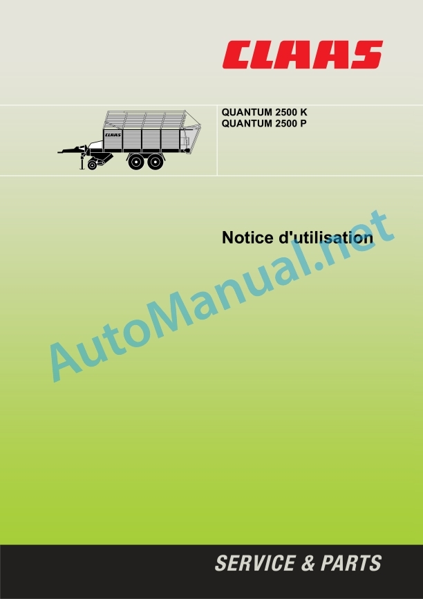
00 0293 129 1.pdf:
1 Machine overview
Quantum 2500K
Quantum 2500P
2 Introduction
Introduction
3 Table of contents
4 Foreword
Important
Nameplate
Driving license
Traffic on public roads
Numberplate
Regular checks according to § 29 StVZO
5 Safety Tips
Use as intended
Marking of warnings and dangers
General safety and accident prevention regulations
Using the PTO shaft
Hydraulic system
Wheels/tyres, bolts
Interview
Sound pressure level
Safety stickers with warning pictograms
6 Technical characteristics
Quantum 2500K
Quantum 2500P
7 Assembly
Assembly
Quantum 2500P
Quantum 2500K
Silage cutting mechanism (optional equipment)
Accessory
Mounting the silage cutting mechanism
Close silage cutting mechanism
8 Before commissioning
Before putting the machine into operation, check the following points!
Coupling
Hydraulic articlted drawbar
Hitch eyes
Drawbar height adjustment
Filling the articulated drawbar pressure accumulator
Cardan shaft
Adapting the cardan shaft
Electrical system
Control panel
Power supply to the tractor’s electrical system (optional equipment)
Hydraulic
Hydraulic system
Connection for locking rotating wheels on the steering axle (optional equipment)
After the self-loader hitch operation
Removing the self-loader
Pneumatic brake system
Two-line system
Maneuvers with a tractor without air brake
Hydraulically operated brake
Parking brake
To apply the brake
To release the brake
Inertia brake
Brake blocks
Uncoupling
Proceed as follows to unhitch the self-loading machine:
Self-loading machines with pneumatic brake
Self-loading machines with hydraulic brake
Self-loading machine with inertia brake
Before transportation
Traveling on public roads
Essential aspects for use
Summary notice
Cutting bucket
Unloading
Articulated drawbar
Lower/raise the pick-up
Folding equipment for dry fodder (Quantum 2500 K)
Adjusting the working height of the pick-up
Moving floor
Adjusting the moving floor speed
Full display
Opening/closing the cutting bucket
Cutting mechanism
Top row of knives
Deploying the upper knives
Lowering the upper knife
Lower row of knives of the silage cutting mechanism (optional equipment)
Extending and folding the silage cutting mechanism
Individual deployment and folding of knives
Unloading
Corridor silo / articulated drawbar
Emptying the box
Starting the self-loader
Loading operation – general information
Traveling on public roads
After use
Steering tag axle (optional equipment)
Emergency response
Moving floor
Other functions
10 Maintenance
Important care instructions
Wheels / tires
Brakes and axles
Pneumatic brake system
Hydraulic system
Lubrication
Security devices
Brakes and axles
Pneumatic brake system
Purge the compressed air tank
Air filter – piping
Cleaning the filter element
Piping Air Filter Elements
Check brake adjustment – brake cylinder piston stroke
Brake linings
00 0293 688 9.pdf:
QUANTUM 3800 KQUANTUM 3800 PQUANTUM 3500 KQUANTUM 3500 PQUANTUM 3500 S
Contents
1 Introduction
1.1 Notes regarding the instructions
1.1.1 Validity of the notice
1.1.2 Information regarding this user manual
1.1.3 Icons and notes
1.1.4 Optional equipment
1.1.5 Qualified specialist workshop
1.1.6 Notes on maintenance
1.1.7 Notes regarding warranty
1.1.8 Spare parts and technical questions
1.2 Use in accordance with instructions
1.2.1 Use in accordance with instructions
1.2.2 Reasonably foreseeable misuse
2 Security
2.1 Recognize the warnings
2.1.1 Warning pictogram
2.1.2 Signal word
2.2 Safety tips
2.2.1 Instructions for use and other sources of information
Meaning of the instructions for use
2.2.2 Staff qualification and organization
Requirements for all users who work on the machine
2.2.3 Danger for children
Children in danger
2.2.4 Hitching the machines
Couple the tractor to the machine
2.2.5 Modifications to the machine
Constructive modifications
2.2.6 Additional equipment and spare parts
Additional equipment and spare parts
2.2.7 Workstations and passengers
Controlling the machine in operation
Passenger co-pilot during work
2.2.8 Technically impeccable condition
Operation only after inspection during proper delivery
Operation only after proper commissioning
Technically impeccable condition of the machine
Danger due to damage to the machine
Respect the technical threshold values
2.2.9 Risk areas
Risk areas
Do not stand between the tractor and the machine
Projection of objects
Danger when the drive is connected
Risks of injury to the PTO
Risks of injury to the PTO
Danger due to machine elements continuing to rotate by inertia
2.2.10 Protective devices
Maintain protective devices capable of operating
2.2.11 Personal protective equipment
Personal protective equipment
Wear suitable clothing
2.2.12 Safety markings
Keep safety stickers legible
2.2.13 Road safety
Dangers when driving on roads and in fields
Tip-over risks
Prepare the machine for road travel
Park the machine safely
Park the tractor with the machine unattended
Protect the machine from foreign bodies
2.2.14 Operating consumables
Unsuitable operating consumables
Safety in handling operating consumables and secondary consumables
Environmental protection and disposal
2.2.15 Sources of risks on the machine
Electrical discharges from the electrical system
Vibrations can cause harm to health
Liquids under pressure
Pressurized air
Hot surfaces
2.2.16 Dangers when getting on and off
Safety when getting on and off
2.3 Safety label
2.3.1 Structure of warning pictograms
2.3.2 Warning pictograms on the machine
3 Description of the machine
3.1 Overview and mode of operation
3.1.1 Overview QUANTUM 3800 K / 3500 K
3.1.2 QUANTUM 3500 S overview
3.1.3 QUANTUM 3800 P / 3500 P overview
3.1.4 Operating mode of the machine
Operating mode of the self-loading trailer and silage trailer
3.2 Optional equipment
3.2.1 Battery cable*
3.2.2 Drawbar extension for Hitch* hitch
3.2.3 Triple* hydraulic connection for the tractor
3.3 Nameplates and identification number
3.3.1 Machine nameplate
3.3.2 Drawbar nameplate
3.3.3 Towing eye rating plate
4 Controls and displays
4.1 Control elements
4.1.1 Cutting bucket
4.1.2 Parking brake
4.1.3 Pneumatic brake
4.1.4 Knives
4.1.5 Command console
5 Technical characteristics
5.1 QUANTUM 3800 K
5.1.1 Dimensions
5.1.2 Weight
5.1.3 Pickup
5.1.4 Cutting bar
5.1.5 Tire pressure
5.1.6 Tractor requirements
5.1.7 Electrical system
5.1.8 PTO regime
5.1.9 Sound pressure level
5.1.10 Lubricants
5.2 QUANTUM 3800 P
5.2.1 Dimensions
5.2.2 Weight
5.2.3 Pickup
5.2.4 Cutting bar
5.2.5 Tire pressure
5.2.6 Tractor requirements
5.2.7 Electrical system
5.2.8 PTO regime
5.2.9 Sound pressure level
5.2.10 Lubricants
5.3 QUANTUM 3500 K
5.3.1 Dimensions
5.3.2 Weight
5.3.3 Pickup
5.3.4 Cutting bar
5.3.5 Tire pressure
5.3.6 Tractor requirements
5.3.7 Electrical system
5.3.8 PTO regime
5.3.9 Sound pressure level
5.3.10 Lubricants
5.4 QUANTUM 3500 P
5.4.1 Dimensions
5.4.2 Weight
5.4.3 Pickup
5.4.4 Cutting bar
5.4.5 Tire pressure
5.4.6 Tractor requirements
5.4.7 Electrical system
5.4.8 PTO regime
5.4.9 Sound pressure level
5.4.10 Lubricants
5.5 QUANTUM 3500 S
5.5.1 Dimensions
5.5.2 Weight
5.5.3 Pickup
5.5.4 Cutting bar
5.5.5 Tire pressure
5.5.6 Tractor requirements
5.5.7 Electrical system
5.5.8 PTO regime
5.5.9 Sound pressure level
5.5.10 Lubricants
6 Preparing the machine
6.1 Stop and immobilize the machine
6.1.1 Disconnect the tractor and the machine and secure them
6.2 Assemble the machine
6.2.1 Summary of parts supplied
6.2.2 Install the wall extensions
6.2.3 Install the cardan shaft on the machine
6.2.4 Install optional equipment
6.3 Access workstations and maintenance stations
6.3.1 Getting in and out of the cargo area
6.4 Adapt the tractor
6.4.1 Coupling device
6.4.2 Harmonize the tractor’s pneumatic braking system
6.5 Adapt the machine
6.5.1 Adapt the hydraulic system
Open hydraulic system (standard system)
Closed hydraulic system
6.5.2 Adjusting the hydraulic articulated drawbar
Hydraulic articulated drawbar – Hitch with towing eye
Adjust the piston rod
Fill the pressure accumulator of the articulated drawbar
6.6 Hitching the machine to the tractor
6.6.1 General advice
6.6.2 Connect the cable for the electricity supply
6.6.3 Connect the control console
6.6.4 Coupling the hydraulic flexible lines
Hydraulic connection
Connection to lock the steering wheels at the steering axle*
6.6.5 Hitch the drawbar with towing eye
6.6.6 Checking the length of the cardan shaft
Shortest operating position of the PTO shaft
Longest operating position of the cardan shaft
6.6.7 Adapting the length of the cardan shaft
6.6.8 Install the cardan shaft
6.6.9 Connect the air brake*
6.6.10 Connect the hydraulic brake*
6.6.11 Raise the stand
6.6.12 Release the parking brake
6.6.13 Remove shims
6.7 Uncouple the machine from the tractor
6.7.1 Notes to follow
6.7.2 Place the wedges
6.7.3 Apply the parking brake
6.7.4 Take out the stand
6.7.5 Remove the cardan shaft
6.7.6 Disconnect the cable for the electricity supply
6.7.7 Remove the control console
6.7.8 Uncouple the hydraulic hose lines
6.7.9 Disconnect the compressed air brake
6.7.10 Disconnect the hydraulic brake* at the tractor
6.8 Loading the machine and securing it
6.8.1 Loading the machine and securing it
7.1 Driving with the self-loading trailer
7.1.1 To check before traveling
7.1.2 Parking the machine with the tractor without a compressed air brake system
7.2 Traveling on the road
7.2.1 General advice
7.2.2 Driving license categories required for Germany
7.2.3 Documents to have with you
7.2.4 Modifications to the machine
7.2.5 Approval obligation and registration obligation
7.2.6 Regular checks according to Article 29 StVZO
7.2.7 Traffic on public roads
7.2.8 Work lights
7.3 To be adjusted before loading
7.3.1 To be adjusted before loading
7.3.2 Adjusting the working height of the pickup
7.3.3 Adjust the baffle
7.4 Loading the trailer
7.4.1 Fill the cargo space evenly
7.4.2 Locking the standard steering axle*
Lock standard steering axle:
Unlock the standard steering axle:
7.5 Unload the trailer
7.5.1 Open the rear hatch
7.5.2 Shared rear hatch
Open the lower and upper rear hatch
Open the lower part of the rear hatch
Fully open the rear hatch
7.6 Start the trailer
7.6.1 Start the self-loading trailer
7.7 Command control console
7.7.1 Command console, general
7.7.2 Load
Folding structure for dry fodder
7.7.3 Moving floor
7.7.4 Open the cutting bucket
7.7.5 Full trailer display
7.7.6 Unload
Empty cargo space
Open the rear hatch
Close the rear hatch
8 Incidents and remedies
8.1 Emergency response
8.1.1 Work steps before emergency order
8.1.2 Manually operate the hydraulic valves
8.2 Chassis
8.2.1 Change the wheel
8.3 Electrical system
8.3.1 Faulty bulbs
9 Maintenance
9.1 Overview of maintenance frequencies
9.1.1 Before harvest
9.1.2 After the first 10 hours of operation
9.1.3 Every 8 operating hours or daily
9.1.4 Every 20 operating hours
9.1.5 Every 100 operating hours
9.1.6 Every 250 operating hours
9.1.7 Every 500 hours of service or annually
9.1.8 Every 1000 operating hours or every 2 years
9.1.9 Every 5 years
9.1.10 After harvest
9.2 Gearbox
9.2.1 Check the tightness of the gearbox
9.2.2 Check the main gearbox oil level
9.2.3 Replace the main gearbox oil
9.2.4 Check timing drum gearbox oil level*
Timing Drum Rear Gearbox
Front Timing Drum Gearbox
9.2.5 Replacing the timing drum gearbox oil
9.2.6 Check the oil level of the moving floor gearbox
9.3 Torque limiter, overload coupling
9.3.1 Check overload coupling
9.3.2 Checking and adjusting the main drive clutch*
9.3.3 Checking and adjusting the timing drum drive clutch*
9.4 Cardan shaft
9.4.1 Maintenance of the cardan shaft*
9.4.2 Remove and install the shaft protection
9.5 Chassis
9.5.1 Check tire pressure
9.5.2 Tighten the wheel nuts
9.5.3 Check the gas spring of the steering axle
9.6 Brake
9.6.1 Carry out a visual check of the braking system
9.6.2 Carry out a functional check of the braking system
9.6.3 Drain the water from the compressed air tank*
9.6.4 Clean the air filter of the tubular line*
9.6.5 Check the brake cylinder piston stroke*
9.6.6 Brake linings
9.7 Workouts
9.7.1 Perform chain maintenance
9.7.2 Check the drive chain
9.7.3 Tighten the pickup drive chain
9.7.4 Checking the main drive chain
9.7.5 Check and tension the distribution drum drive chains*
Tighten the left side drive chain
Tighten the right side drive chain
9.8 Hydraulic system
9.8.1 Relieve hydraulic system pressure
9.8.2 Check hydraulic hose lines
9.8.3 Check the pressure accumulator
9.8.4 Check the pressure limiter and adjust it
9.9 Electrical and electronic system
9.9.1 Check lighting
9.9.2 Adjusting the reed switch
9.10 Pickup
9.10.1 Check the wheels
9.10.2 Checking automatic chain lubrication
9.11 Cutting bucket
9.11.1 Opening and closing the cutting bucket
Open cutting bucket
Close the cutting bucket
9.11.2 Checking the knives
9.11.3 Remove the knives
9.11.4 Place the knives
9.11.5 Adjust the preload of the knives
9.11.6 Adjusting the cutting bucket
9.11.7 Check the cutting bucket pressure spring
9.11.8 Adjust the scraper box
9.11.9 Clean the cutting bucket
9.12 Moving floor
9.12.1 Check conveyor bars
9.12.2 Tighten the moving floor chains
9.13 Assembly parts and bodywork
9.13.1 Adjust the rear hatch
Adjust the hydraulic cylinder
Adjust the support
9.13.2 Check the rear hatch pressure spring
9.13.3 Check the shims
9.13.4 Dispose of leftover harvest
9.13.5 Check the mounting hardware
9.13.6 Clean the machine
9.13.7 Precautionary measures for the machine
9.14 Lubrication plan
9.14.1 Lubricate the lubrication points every 8 operating hours
9.14.2 Lubricate the lubrication points every 20 operating hours
9.14.3 Lubricate the lubrication points every 100 operating hours
10 Decommissioning and disposal
10.1 General information
10.1.1 Decommissioning and disposal
11 CE declaration of conformity
11.1 QUANTUM 3800 K / 3800 P / 3500 K / 3500 P / 3500 S
11.1.1 Declaration of conformity for EEC
12 Technical terms and abbreviations
12.1 Terms and explanations
12.1.1 Abbreviations
12.1.2 Technical terms
John Deere Repair Technical Manual PDF
John Deere Parts Catalog PDF
John Deere Tractors 7500 Parts Catalog CPCQ26568 30 Jan 02 Portuguese
John Deere Repair Technical Manual PDF
John Deere POWERTECH E 4.5 and 6.8 L Diesel Engines TECHNICAL MANUAL 25JAN08
John Deere Repair Technical Manual PDF
John Deere Repair Technical Manual PDF
John Deere Repair Technical Manual PDF
John Deere Application List Component Technical Manual CTM106819 24AUG20
John Deere Repair Technical Manual PDF
John Deere Repair Technical Manual PDF
John Deere Parts Catalog PDF
John Deere Harvesters 8500 and 8700 Parts Catalog CPCQ24910 Spanish


