Claas Quantum 6800-4500 Gt P (615) Loader Wagons Operator Manual EN
$50.00
- Model: Quantum 6800-4500 Gt P (615) Loader Wagons
- Type Of Manual: Operator Manual
- Language: EN
- Format: PDF(s)
- Size: 74.0 MB
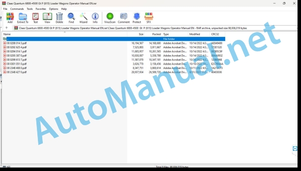
File List:
00 0288 014 3.pdf
00 0292 625 4.pdf
00 0294 014 1.pdf
00 0295 387 0.pdf
00 0299 613 7.pdf
00 0301 051 0.pdf
00 2348 408 0.pdf
00 2348 427 0.pdf
00 0288 014 3.pdf:
EASY on board app
Table of contents
1 Introduction
1.1 General information
1.1.1 Validity of the manual
1.1.2 Information about this Operator’s Manual
1.1.3 Symbols and notes
1.1.4 Qualified specialist workshop
1.1.5 Maintenance notes
1.1.6 Notes on warranty
1.1.7 Spare parts and technical questions
1.1.8 Technical requirements
1.2 Intended use
1.2.1 Intended use
1.2.2 Reasonably foreseeable misuse
2 Safety
2.1 Identifying warnings
2.1.1 Hazard signs
2.1.2 Signal word
2.2 Safety rules
2.2.1 Meaning of Operator’s Manual
2.2.2 Requirements made on all persons working with the product
2.2.3 Hazard areas
2.2.4 Check interactions with self-propelled machines / tractors and implements
2.2.5 Structural changes
2.2.6 Optional equipment and spare parts
2.2.7 Technical status
2.2.8 Hazard caused by damage to the product
2.2.9 Visibility of work area
2.2.10 Glare and reflections
2.2.11 Unintentional triggering of functions
2.2.12 Hazards caused by signal tones
2.2.13 Unauthorised use
2.2.14 Use of mobile terminal outside the cab
2.2.15 Follow the safety instructions
2.2.16 Respecting technical limit values
2.2.17 Preparing the product for road travel
2.2.18 Hazards when driving on the road and on the field
2.2.19 Hazards when driving on the road with an ISOBUS implement
2.2.20 Switching off the mobile terminal while driving
2.2.21 Hazards from disturbance of WLAN environment
2.2.22 Hazards from covering up the App
2.2.23 Hazards caused by malfunctions of the app
2.2.24 Raised machine parts and loads
3 Product description
3.1 Overview and method of operation
3.1.1 Overview of CWI
3.1.2 Functions of CWI
3.2 Identification plates and identification numbers
3.2.1 CWI identification plate
3.3 Information on the product
3.3.1 Factory settings
3.3.2 Software and hardware version
3.3.3 Seal on the CWI
4 Operating and display elements
4.1 CLAAS Wireless Interface (CWI)
4.1.1 CWI operating elements
4.2 CWI Setup App
4.2.1 Overview of screen
4.2.2 Buttons
4.2.3
4.2.4
4.2.5
5 Technical specifications
5.1 CLAAS Wireless Interface (CWI)
5.1.1 Specification
6 Preparing the product
6.1 Installing the product
6.1.1 Installing the CWI Setup app
6.1.2 Installing the EASY on board app
6.1.3 Connecting the tablet
7 Operation
7.1 Initial operation
7.1.1 Establishing the WLAN connection for the first time
7.1.2 Changing factory settings
7.1.3 Establishing the WLAN connection
7.2 CWI Setup App
7.2.1 Calling up menus
7.2.2 Establishing a secure data connection
7.2.3 Deleting a secure data connection
7.2.4 Displaying the software version
7.3 CWI Setup – Settings
7.3.1 Changing settings
7.3.2 Switching LEDs on and off
7.4 CWI setup – Advanced settings
7.4.1 Deleting the connection partner in CWI
7.4.2 Deleting the connection partner on the tablet
7.4.3 Resetting the CWI to factory settings
7.4.4 Resetting the tablet to factory settings
7.4.5 Switching the CAN filter on and off
7.5 EASY on board App
7.5.1 Launching Operator’s Manual
8 Faults and remedies
8.1 Overview of problems
8.1.1 CWI faults
8.1.2 Fault message: USB charging connection was disconnected
8.1.3 Fault message: Tablet outside WLAN reception area
8.1.4 Fault message: Screen locked
9 Maintenance
9.1 Maintenance schedules
9.1.1 Daily
9.2 Tablet
9.2.1 Cleaning the tablet
9.2.2 Downloading software updates
9.2.3 Updating the operating system
10 Putting out of operation and disposal
10.1 General information
10.1.1 Decommissioning and disposal
11 EC declaration of conformity
11.1 CLAAS Wireless Interface (CWI)
11.1.1 EU Declaration of conformity
12 Technical terms and abbreviations
12.1 Terms and explanations
12.1.1 Abbreviations
12.1.2 Technical terms
00 0292 625 4.pdf:
COMMUNICATOR II
Table of contents
1 Introduction
1.1 Notes on the manual
1.1.1 Validity of manual
1.1.2 Information about this Operator’s Manual
1.1.3 Symbols and notes
1.1.4 Optional equipment
1.1.5 Qualified specialist workshop
1.1.6 Maintenance notes
1.1.7 Notes on warranty
1.1.8 Spare parts and technical questions
1.2 Intended use
1.2.1 Intended use
1.2.2 Reasonably foreseeable misuse
2 Safety
2.1 Identifying warnings
2.1.1 Hazard signs
2.1.2 Signal word
2.2 Safety rules
2.2.1 Meaning of Operator’s Manual
2.2.2 Requirements made on all persons working with the product
2.2.3 Hazard areas
Hazard areas
2.2.4 Interaction between the control terminal and the machine or tractor
2.2.5 Structural changes
2.2.6 Optional equipment and spare parts
2.2.7 Technical status
2.2.8 Danger from damage to the machine
2.2.9 Complying with technical limit values
2.2.10 Preparing the product for road travel
2.2.11 Hazards when driving on the road and in the field
2.2.12 Hazards when driving on the road with an ISOBUS implement
2.2.13 Switching off the terminal while driving
2.2.14 Electrocution by electrical system
2.2.15 Only carry out work on the machine when it is stopped
2.2.16 Maintenance operations and repair work
2.2.17 Raised machine parts and loads
2.2.18 Welding work prohibited
3 Product description
3.1 Overview and method of operation
3.1.1 Overview of COMMUNICATOR II
3.1.2 Function of COMMUNICATOR II
3.2 Identification plates and identification numbers
3.2.1 Identification plate of COMMUNICATOR II
4 Operating and display elements
4.1 COMMUNICATOR II
4.1.1 Terminal
4.1.2 Terminal program
4.2 Universal terminal menu structure (service)
4.2.1 Main menu of universal terminal
4.2.2
4.2.3
4.2.4
4.2.5
4.3 Job processing (task) menu structure
4.3.1 Job processing main menu
4.3.2
4.3.3
4.3.4
4.3.5
4.3.6
5 Technical specifications
5.1 COMMUNICATOR II
5.1.1 Specification
6 Preparing the product
6.1 Switching off and securing the machine
6.1.1 Shut down and secure the machine
7 Operation
7.1 Switching COMMUNICATOR II on/off
7.1.1 Switching COMMUNICATOR II on
7.1.2 Selecting the application
7.1.3 Switching off COMMUNICATOR II
7.2 Programmable keys
7.2.1 Displaying the key assignment
7.2.2 Creating a key assignment
Step 1: Selecting the control and the key
00 0294 014 1.pdf:
1 Machine overview
2 Introduction
Introduction
Validity
3 Contents
4 Preface
Of special importance
Identification plate
Road transport
Operating permit
Operating on public roads
Number plate
Regular inspection as required by law
5 Safety rules
Designated use
Identification of warning and danger signs
General Safety and Accident Prevention Instructions
PTO Operation
Hydraulic system
Wheels and tyres, threaded fastenings
Maintenance
Sound pressure level
Safety decals with pictorials
6 Specifications
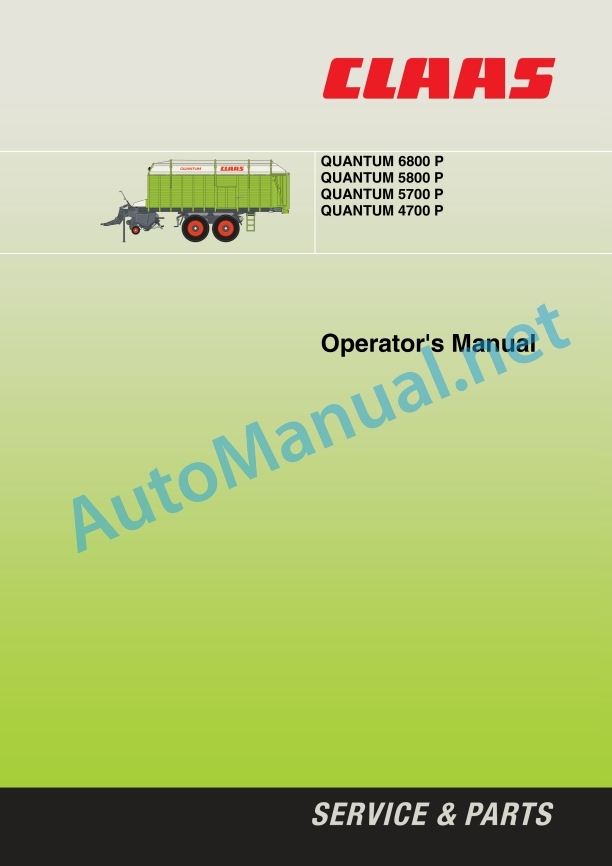
QUANTUM 6800 P
QUANTUM 5800 P
QUANTUM 5700 P
QUANTUM 4700 P
7 Assembly
Assembly
QUANTUM 6800 P / 5800 P / 5700 P
QUANTUM 4700 P
Hitching the machine for the first time
8 Prior to Operation
Check and observe the following before operation
Coupling to the tractor
Hydraulic articulated drawbar
Ring hitches
Hydraulic articulated drawbar – automatic pick-up hitch
Drawbar height adjustment
Power steering hitching (optional equipment)
Basic setting
Setting the collision protection of the power steering
Setting the power steering
Checking/adjusting the hydraulic pressure
Drive shaft
Adjusting the universal drive shaft
Universal drive shaft with CC taper lock seal
Coupling
Uncoupling
Tractor lower link
Electrical system
Control unit
Lighting equipment
ABS air brake system
ABS function test
Hydraulic system
Open hydraulic system (standard system)
Closed hydraulic system
Power-beyond connector
Hydraulic coupling for standard steering axle (optional equipment, only available ex-works)
Adjusting flow on the hydraulic control block
Support foot
After hitching the forage wagon
Parking the self-loading forage wagon
Air brake system
Two-line system
Towing with tractors without air brake system
Hydraulically operated brake system
Hydraulic emergency brake
Connection
Parking brake
Applying the hand brake
Releasing the brake
Wheel chocks
Access hatch (only QUANTUM 6800 P / 5800 P)
Unhitching
Forage wagon with air brake system
Forage wagon with hydraulically operated brake
Forage wagon with ABS air brake system
Prior to transportation
Hydraulic drawbar damping (optional equipment, only available ex-works)
Activate drawbar damping
Driving on public roads
9 Operation
Brief introduction
Loading operation
Unloading operation
Articulated drawbar
Indicator lights
2-speed motor (optional equipment, only available ex-works)
Loading operation
Lowering and raising the pick-up
Preselecting the working height of the pick-up
Roller crop guard (QUANTUM 6800 P / 5800 P)
Baffle plate (QUANTUM 5700 P / 4700 P)
Knife frame opening/closing
Engaging floor conveyor – filling the loading bay
Unloading operation
Open tailgate
Emptying the loading bay
2-speed motor for floor conveyor (optional equipment, only available ex-works)
Close tailgate
Loading bay illumination:
Operation of forage wagon
Loading operation (general)
After use
Standard steering axle (optional equipment, only available ex-works)
Locking the standard steering axle
Unlocking the standard steering axle
Emergency control
Optional equipment
Tractor electrical system power supply
Control unit extension cable
Load-Sensing hydraulics control line
Drawbar extension for automatic pick-up hitch(M01/0010)
Hydraulic connection for tractor (R03/0070)
Slip yoke kit
10 Maintenance
Important Maintenance Instructions
Wheels / tyres
Brakes and axles
Air brake system
Hydraulic system
Lubrication
Brakes and axles
Air brake system
ABS air brake system
Draining compressed air reservoir
Air pipe filter
Cleaning the filter element
Components of the air cleaner
Adjusting the brake – checking the brake cylinder piston stroke
Brake regulator
Brake linings
Power steering
Topping up/bleeding the power steering
Bleeding the steering cylinder
Bleeding the steering cylinder
Setting the stroke of the steering cylinder
Extending the steering cylinder
Retracting the steering cylinder
Setting the operating pressure – power steering
Cutting mechanism
Changing the cutting knives
Knife removal
Knife installation
Adjusting the cutterbar trough
Adjusting the stripper housing
Drive systems
Main gearbox
QUANTUM 6800 P / 5800 P (Gearbox Item No.: 0973 300.0)
QUANTUM 5700 P / 4700 P (Gearbox Item No.: 0972 140.0)
Venting valve
Floor conveyor gearbox
Floor conveyor drive with 2-speed motor
QUANTUNM 6800 P / 5800 P / 5700 P (roll floor shaft ø 45 mm)
QUANTUM 4700 P (roll floor shaft ø 40 mm)
Rotor drive
QUANTUM 6800 P / 5800 P (Gearbox Item No.: 0973 301.1)
QUANTUM 5700 P / 4700 P (Gearbox Item No.: 0973 492.0)
Tensioning the drive chains
Tensioning the pick-up drive chain
Floor conveyor chains
Floor conveyorhain (up to year of manufacture 2006)
Floor conveyor chain (from year of manufacture 2007)
Cam-type cut-out clutch
Drive shaft
Air suspension
Raising and loring device for air-suspension axles
Electrical system
Adjusting the reed switches
Hydraulic system
Changing pressure filter
Accumulator
Hydraulic hose connections
Gas shock absorber
Wheel changing
Guide rollers
Maintenance and lubrication holes
Threaded fasteners
Fasteners
Cleaning and care
Daily cleaning
End of season storage
Lubrication chart
Drive systems
Lubrication points
11 Lubrication Chart
Safety Rules
Lubricants
Lubrication
00 0295 387 0.pdf:
1 Introduction
1.1 General information
2 Contents
3 Preface
3.1 Of special importance
4 Safety instructions
4.1 Safety rules
4.1.1 Identification of warning and danger signs
4.2 Safety decals with pictorials
5 Carry out before initial use
5.1 Adapting to the tractor
5.1.1 Bracket Terminal / CLAAS Communicator
5.1.2 Ballast
5.2 Assembling / adapting the machine
5.2.1 Matching the hydraulics
Open hydraulic system (standard system)
Closed hydraulic system
5.2.2 Fitting the Load-Sensing Hydraulics control line
5.2.3 Connecting the silaging material unit
6 Carry out before each start-up
7 Mounting and removing the machine
7.1 Removing the machine
Proceed as follows to mount the mount:
7.1.1 Connecting ISOBUS Terminal
7.2 Removing / storing the machine
8 Driving and transportation
8.1 Road transport
8.1.1 Transportation by road
8.2 Transport position with ISOBUS Terminal
9 Operation – CLAAS Communicator
9.1 CLAAS Communicator
9.1.1 Overview – Hardware keys
9.1.2 Overview – Display
9.1.3 “Soft-Keys”
9.1.4 Soft-Key “STOP”
9.1.5 Switching the CLAAS Communicator on / off
9.1.6 “Menu Selection” button
9.1.7 “Terminal” button
9.2 Service Menu
9.2.1 Serv
9.2.2 Brightness and contrast
Changing the contrast of the screen
Changing the brightness of the screen
9.2.3 Setting the date / time of day
9.2.4 Software care
Freeing memory space
9.2.5 Country-specific settings
9.2.6 Aux
10 Operation – ISOBUS Terminal
10.1 General information
10.2 Display
10.2.1 Overview – Display
10.2.2 Title Bar
10.2.3 Menu Bar
10.2.4 Soft-Key Symbols
10.2.5 Status Bar
10.2.6 Data Field
10.2.7 Data field symbols
10.2.8 Software version
10.2.9 Service Menu / memory management
10.3 Starting the control programme
10.4 Menu “Transport”
10.4.1 Call up the menu “Transport”
10.4.2 “Soft Keys” – Menu “Transport”
10.5 Menu “Loading”
10.5.1 Call up menu “Loading”
10.5.2 “Soft Keys” – Menu “Loading”
10.6 Menu “Unloading”
10.6.1 Call up the menu “Unloading”
10.6.2 “Soft Keys” – Menu “Unloading”
10.7 Adjusting the artiading area lighting / additional lighting
10.9 Menu “Setup”
10.9.1 Call up the menu “Setup”
10.9.2 “Soft Keys” – Menu “Setup”
10.9.3 Data field – Menu “Setup”
10.9.ance counter
Switching on / off the silaging material feed
Deposition direction – setting the cross conveyor
10.9.5 Leaving the “Setup” menu
10.10 Menu “Order management”
10.10.1 Calling up the “Order management” menu
10.10.2 “Soft Keys” – Menu “Order management”
10.10.3 Data field – menu “Order management”
10.10.4 Order storing
Moving the insertion marker (M)
Deleting text
Entering text
Ending the input
Activating the order
Leaving the menu “Order management”
10.11 Information system
10.11.1 Calling up the “info” menu
10.11.2 “Soft Keys” – Menu “Info”
10.11.3 Data field – Menu “Info”
Symbols error messages
0.12 Manual mode
10.12.1 Of special importance
10.13 Manual mode “Loading”
10.13.1 Calling up the menu “Manual loading”
10.13.2 Operating the pickup
10.13.3 Operating the floor conveyor
10.13.4 End of loading operation
10.13.5 Ending thng”
10.14.1 Calling up the menu “Manual unloading”
10.14.2 Operating the tailgate
10.14.3 Operating the floor conveyor
10.14.4 Switching on / off of the shredder drums
10.14.5 Cross conveyor – changing the direction of rotation
10.14.6 Ending the manual mode “Unloading”
10.15 Basic setting (initialisation)
10.15.1 Starting the initialisation sequence
11 Field use
11.1 General information
11.1.1 Notes concerning automatic operation
11.2 Automatic mode “Loading”
11.2.1 Starting the automatic operation “Loading”
11.2.2 Headland – Lifting / lowering pickup
11.2.3 Floor conveyor control
11.2.4 Switch on the floor conveyore knife frame
11.2.6 Opening / closing the knife frame completely
11.2.7 Feed chute – removing blockages
11.2.8 Filling level indicator (optional equipment)
11.2.9 End of loading operation
11.2.10 Ending the automatic mode “Loading”
11.3 Automatic mode “Unloading”
11.3.1 Starting the automatic.2 Floor conveyor control
11.3.3 Switching the floor conveyor on / off
11.3.4 Reversing the floor conveyor drive
11.3.5 Changing the floor conveyor drive
11.3.6 Ending automatic mode “Unloading”
11.4 Steering axle
11.4.1 General information
11.4.2 Lock / unlock the steering axle
12 Malfunctions and remedies
12.1 Error messages on the display
Sensor error
PTO shaft switched on!
Fault finding
12.2 General errors
00 0299 613 7.pdf:
1 Machine overview
2 Introduction
Introduction
Validity
3 Contents
4 Preface
Of special importance
Identification plate
Road transport
Operating on public roads
Number plate
Regular inspection as required by law
5 Safety Rules
Designated use
Identification of warning and danger signs
General Safety and Accident Prevention Instructions
PTO Operation
Hydraulic system
Wheels and tyres, threaded fastenings
Maintenance
Sound pressure level
Sy decals with pictorials
6 Specifications
QUANTUM 6800 P
QUANTUM 5500 P-18
QUANTUM 6500 P
QUANTUM 5500 GT / 5500 P-16
QUANTUM 5500 P
QUANTUM 4500 P
7 Assembly
Assembly
QUANTUM 6800 P / 5500 P-18 up to serial no. 615 0 2366
QUANTUM 6500 P (Spain only)
QUANTUM 5500 P-16 / 5500 GT / 5500 P up to serial no. 615 0 2366
QUANTUM 4500 P up to serial no. 615 0 2366
QUANTUM 6800 P / 5500 P-18 from serial no. 615 0 2367
QUANTUM 5500 P-16 / 5500 P from serial no. 615 0 2367
Coupling machine for the first time
8 Before Operation
Check and observe the following before operation
Coupling to the tractor
Hydraulic articulated drawbar
Ring hitches
Hydraulic articulated drawbar – automatic pick-up hitch
Automatic pick-up hitch only – Spain
Height adjustment of the drawbar
Coupling the forced steering system (optional equipment)
Adjusting forced steering system
Checking and adjusting the hydraulic pressure
Drive shaft
Adjusting the universal drive shaft
Universal drive shaft with CC taper lock seal
Coupling
Uncoupling
Electrical system
Control unit
Lighting equipment
ABS air brake system
ABS function test
Hydraulic system
Open hydraulic system (standard system)
Closed hydraulic system
Power-beyond connector
Standard steering axle hydraulic connection (optional equipment)
Adjusting flow on the hydraulic control block
Support foot
After attaching the self-loading forage wagon
Parking the self-loading forage wagon
Air brake system
Two-line system
Towing with tractors without air brake system
Hydraulically operated brake system
Parking brake
Setting brake
Releasing brake
Wheel chocks
Inspection hatch
Unhitching
Self-loading forage wagon with air brake system
Self-loading forage wagon with hydraulically operated brake
Self-loading forage wagon with ABS air brake system
Prior to transportation
Hydraulic drawbar damping (optional equipment, only available ex-works)
Activate drawbar damping
Driving on public roads
9 Operation
Brief introduction
Loading operation
Unloading operation
Articulated drawbar
Indicator lights
2-speed motor (optional equipment)
Loading operation
Lowering and lifting the pick-up
Preselecting the working height of the pick-up
Roll-type crop guard (QUANTUM 6800 P / 5500 P-18)
Baffle plate (QUANTUM 6500 P / 5500 P-16 / 5500 GT / 5500 P / 4500 P)
Opening knife frame hydraulically
Engaging floor conveyor – filling load space
Unloading operation
Open tailgate
Unloading the load space
Floor conveyor 2-speed motor (optional equipment)
Close tailgate
Loading space lighting:
Operation of self-loading forage wagon
Loading operation (general)
After use
Standard steering axle (optional equipment, only available ex-works)
Locking the standard steering axle
Unlocking the standard steering axle
Emergency control
Optional equipment
Tractor electrical system power supply
Control unit extension cable
Load-Sensing hydraulics control line
Drawbar extension for automatic pick-up hitch (M01/0010)
Hydraulic connection for tractor (R03/0070)
Push-on yoke kit
10 Maintenance
Important Maintenance Instructions
Wheels/tyres
Brakes and axles
Compressed-air actuated brakes
Hydraulic system
Lubrication
Brakes and axles
Air brake system
ABS air brake system
Draining compressed air reservoir
Air pipe filter
Cleaning the filter element
Components of the air cleaner
Adjusting the brake – checking the brake cylinder piston stroke
Brake regulator
Brake linings
Forced steering system
Refilling and bleeding the forced steering system
Bleeding steering cylinder
Bleeding master cylinder
Adjusting stroke of master cylinder
Extending master cylinder
Retracting master cylinder
Setting operating pressure for forced steering system
Cutting mechanism
Changing the cutting knives
Knife removal
Knife installation
Adjusting the scraper unit
Drive systems
Main gearbox
Floor conveyor gearbox
Floor conveyor drive with 2-speed motor
Rotor drive
Tensioning the drive chains
Tensioning pick-up drive chain
Floor conveyor chains
Air bounce
Lifting and lowering device for air-cushioned axles
Electrical system
Adjusting the reed switches
Hydraulic system
Changing pressure filter
Pressure accumulator
Hydraulic hose connections
Gas shock absorber
Drive shaft
Cam-type cut-out clutch
Maintenance and lubrication holes
Screw connections
Fasteners
End of season storage
Lubrication chart
11 Lubrication Chart
Safety Rules
Lubricants
Lubrication
00 0301 051 0.pdf:
PROFI CAM 3
Table of contents
1 Introduction
1.1 Notes on the manual
1.1.1 Validity of manual
1.1.2 Information about this Operator’s Manual
1.1.3 Symbols and notes
1.1.4 Optional equipment
1.1.5 Qualified specialist workshop
1.1.6 Maintenance information
1.1.7 Warranty notes
1.1.8 Spare parts and technical questions
1.2 Intended use
1.2.1 Intended use
1.2.2 Reasonably foreseeable misuse
2 Safety
2.1 Identifying warnings
2.1.1 Hazard signs
2.1.2 Signal word
2.2 Safety rules
2.2.1 Meaning of Operator’s Manual
2.2.2 Observing safety decals and warnings
2.2.3 Optional equipment and spare parts
3 Product description
3.1 Overview and method of operation
3.1.1 How the PROFI CAM works
3.2 Identification plates and identification number
3.2.1 Position of identification plates
3.2.2 Explanation of PROFI CAM identification plate
3.3 Information on the product
3.3.1 CE marking
4 Operating and control elements
4.1 Camera system
4.1.1 Camera system monitor
4.2 Menu structure
4.2.1 Main menu
4.2.2
4.2.3
4.2.4
4.2.5
4.2.6
5 Technical specifications
5.1 PROFI CAM
5.1.1 Monitor
5.1.2 Camera
5.1.3 Switch box
5.1.4 Degree of protection against foreign bodies and water
6 Preparing the product
6.1 Shutting down and securing the machine
6.1.1 Switching off and securing the machine
6.2 Prior to operation
6.2.1 Carry out prior to operation
6.2.2 Installing the sun protection
6.2.3 Aligning the camera
6.2.4 Connecting the camera electrics
7 Operation
7.1 Monitor
7.1.1 Switching on the monitor
7.1.2 Calling up the menu
7.1.3 Setting a menu item
7.1.4 Setting the image orientation
7.1.5 Setting automatic screen darkening
7.1.6 Image mirroring
7.1.7 Setting the trigger view
7.1.8 Setting the follow-up time for trigger view
7.1.9 Setting the display mode
7.1.10 Activating/deactivating a display mode
8 Faults and remedies
8.1 Electrical and electronic system
8.1.1 Overview of problems on PROFI CAM camera system
8.1.2 Replacing the switch box fuse
9 Maintenance
9.1 Maintenance intervals
9.1.1 Every 10 operating hours or daily
9.2 Camera system
9.2.1 Checking the camera system for dirt
9.2.2 Cleaning the camera
9.2.3 Cleaning the switch box
9.2.4 Cleaning the monitor
10 Placing out of operation and disposal
10.1 General Information
10.1.1 Putting out of operation and disposal
11 Technical terms and abbreviations
11.1 Abbreviations
11.1.1 Units
11.1.2 Abbreviations
11.1.3 Technical terms
00 2348 408 0.pdf:
CEMIS 100
Table of contents
1 Introduction
1.1 General information
1.1.1 Validity of the manual
1.1.2 Information about this Operator’s Manual
1.1.3 Symbols and notes
1.2 Intended use
1.2.1 Intended use
1.2.2 Reasonably foreseeable misuse
2 Safety
2.1 Safety rules
2.1.1 General safety and accident prevention regulations
2.1.2 Interaction between terminal and machine or tractor
2.1.3 Electrocution by electrical system
3 Product description
3.1 Overview and method of operation
3.1.1 Overview of CEMIS 100
3.1.2 Function principle of CEMIS 100
3.2 Identification plates and identification numbers
3.2.1 Spare parts and technical questions
3.2.2 Identification plate of CEMIS 100
4 Operating and display elements
4.1 CEMIS 100
4.1.1 User interface for LINER
4.1.2 User interface for ROLLANT
4.1.3 User interface for UNIWRAP
5 Technical specifications
5.1 CEMIS 100
5.1.1 Specification
6 Operation
6.1 CEMIS 100
6.1.1 Operating the CEMIS 100
6.1.2 Switching CEMIS 100 on
6.1.3 Switching CEMIS 100 off
7 Maintenance
7.1 CEMIS 100
7.1.1 Daily
8 Putting out of operation and disposal
8.1 General information
8.1.1 Removal from service and disposal
9 Technical terms and abbreviations
9.1 Terms and explanations
9.1.1 Technical words
9.1.2 Abbreviations
00 2348 427 0.pdf:
CEMIS 700
Table of contents
1 Introduction
1.1 General information
1.1.1 Validity of the manual
1.1.2 Information about this Operator’s Manual
1.1.3 Symbols and notes
1.2 Intended use
1.2.1 Intended use
1.2.2 Reasonably foreseeable misuse
2 Safety
2.1 Safety rules
2.1.1 General safety and accident prevention regulations
2.1.2 Interaction between terminal and machine or tractor
2.1.3 Electrocution by electrical system
3 Product description
3.1 Overview and method of operation
3.1.1 Overview of CEMIS 700
3.1.2 Function principle of CEMIS 700
3.2 Identification plates and identification numbers
3.2.1 Spare parts and technical questions
3.2.2 Identification plate of CEMIS 700
4 Information on the product
4.1 Software version
5 Operating and display elements
5.1 CEMIS 700
5.1.1 User interface
5.1.2 Terminal program
6 Technical specifications
6.1 CEMIS 700
6.1.1 Specification
7 Operation
7.1 CEMIS 700
7.1.1 Operating the CEMIS 700
7.1.2 Switching CEMIS 700 on
7.1.3 Switching CEMIS 700 off
7.2 Terminal settings
7.2.1 Makin
John Deere Repair Technical Manual PDF
John Deere Diesel Engines POWERTECH 2.9 L Component Technical Manual CTM126 Spanish
John Deere Repair Technical Manual PDF
John Deere 16, 18, 20 and 24HP Onan Engines Component Technical Manual CTM2 (19APR90)
John Deere Repair Technical Manual PDF
John Deere 18-Speed PST Repair Manual Component Technical Manual CTM168 10DEC07
John Deere Repair Technical Manual PDF
John Deere DF Series 150 and 250 Transmissions (ANALOG) Component Technical Manual CTM147 05JUN98
John Deere Parts Catalog PDF
John Deere Tractors 7500 Parts Catalog CPCQ26568 30 Jan 02 Portuguese
John Deere Repair Technical Manual PDF
John Deere Repair Technical Manual PDF
John Deere Repair Technical Manual PDF
John Deere Repair Technical Manual PDF

