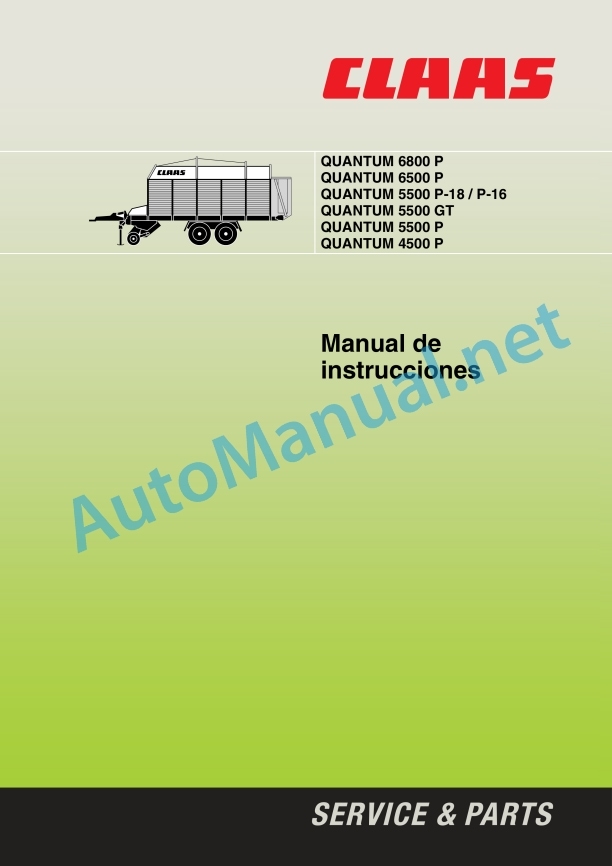
Claas Quantum 6800-4500 Gt P (615) Loader Wagons Operator Manual ES
$50.00
- Model: Quantum 6800-4500 Gt P (615) Loader Wagons
- Type Of Manual: Operator Manual
- Language: ES
- Format: PDF(s)
- Size: 84.6 MB
File List:
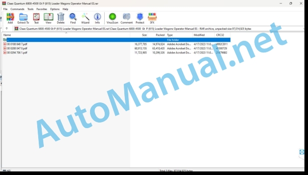
00 0188 848 7.pdf
00 0288 047 0.pdf
00 0294 706 1.pdf
00 0188 848 7.pdf:
1 Machine overview
2 Introduction
Introduction
Validity
4 Prologue
To observe in particular
Identification plate
Circulation on public roads
Circulation permit
Driving on public roads
License plate
Regular checks under art. 29 StVZO
5 Security measures
Use in accordance with the intended standards
Warning and danger signs
General safety and accident prevention rules
PTO shaft operation
Hydraulic system
Wheels/tyres, bolted joints
Maintenance
Noise level
Safety decals with warning symbols
6 Technical data
QUANTUM 6800P
QUANTUM 5500 P-18
QUANTUM 6500P
QUANTUM 5500 GT / 5500 P-16
QUANTUM 5500P
QUANTUM 4500P
7 Assembly
Mounting
QUANTUM 6800 P / 5500 P-18 up to machine number 615 0 2366
QUANTUM 6500 P (only for Spain)
QUANTUM 5500 P-16 / 5500 GT / 5500 P up to machine number 615 0 2366
QUANTUM 4500 P up to machine number 615 0 2366
QUANTUM 6800 P / 5500 P-18 from machine number 615 0 2367
QUANTUM 5500 P-16 / 5500 P from machine number 615 0 2367
Docking the machine for the first time
8 Before start-up
Check and observe before commissioning!
Hydraulic articulated lance
Shooting eyelets
Hydraulic articulated drawbar – Hitch coupling
Hitch coupling only – Spain
Lance height adjustment
Engage forced steering (additional equipment)
Adjust forced steering
Check/adjust hydraulic pressure
articulated axle
Articulated axle adaptation
Articulated shaft with CC clamping cone lock
Disengage
Electric system
Control panel
Driving lighting
ABS pneumatic brake system
ABS operation check
Hydraulic system
Open hydraulic system (standard system)
Closed hydraulic system
Take Power – beyond
Standard steering axle hydraulic connection (additional equipment)
Adjust the flow rate in the hydraulic system control block
Support leg
After coupling the self-loading trailer
Stopping the self-loading trailer
Pneumatic brake system
Double pipe system
Maneuvering tractor vehicles without a pneumatic brake system
Hydraulic brake
Parking break
Apply the brake
Release the brake
Access door
Disengage
Self-loading trailer with pneumatic brake system
Self-loading trailer with hydraulic brake
Self-loading trailer with ABS pneumatic brake system
Before transportation
Hydraulic drawbar suspension (additional equipment, only available ex factory)
Activate the drawbar damping
Road walking
9 Handling
Brief instructions
Discharge
articulated lance
Control witnesses
Two-phase motor (additional equipment)
Lower/raise the Pick-up
Preset the working height of the Pick-up
Roller tamper (QUANTUM 6800 P / 5500 P-18)
Retainer (QUANTUM 6500 P / 5500 P-16 / 5500 GT / 5500 P / 4500 P)
Open the knife box hydraulically
Connect the friction bottom – Fill the cargo space
Discharge
Open the tailgate
Empty the cargo compartment
Two-phase friction bottom motor
Close the tailgate
Cargo space lighting
Putting the self-loading trailer into service
General charging process
After use
Standard steering axle (Additional equipment, only available ex factory)
Standard steering axle lock
Standard steering axle release
Emergency management
Additional equipment
Tractor electrical system power supply
Control panel extension cable
Load-Sensing Hydraulic System Control Pipe
Lance extension for Hitch coupling (M01/0010)
Hydraulic connection for tractor (R03/0070)
Insert Fork Kit
10 Maintenance
Important maintenance instructions
Wheels/tyres
Brakes and axles
Air brakes
Hydraulic system
Lubrication
Protection devices
Brakes and axles
Pneumatic brake system
ABS pneumatic brake system
Bleed the pressurized air tank of water
Pipes air filter
Clean the filter element
Disassembled pipe air filter
Brake adjustment – Check brake cylinder piston stroke
Brake force regulator
brake linings
Forced direction
Fill/bleed forced direction
Bleed the steering cylinder
Bleed control cylinder
Adjust control cylinder stroke
Extend control cylinder
Pick up the control cylinder
Adjust the operating pressure of the forced steering
Cutting mechanism
Blade change
Disassembly of the blades
Blade assembly
Adjust the scraper box
main gear
Friction bottom gear
Friction bottom gear with two-phase motor
rotor gear
Retensioning of drive chains
Tension the Pick-up drive chain
Friction bottom chains
Air suspension
Lifting and lowering device for air suspension axles
Electric system
Adjusting Reed Switches
Hydraulic system
Change the pressure filter
pressure accumulator
Flexible hydraulic system pipes
Pressure gas spring
articulated axle
Pawl Clutch
Maintenance and lubrication openings
Protection devices
Screwed joints
Union elements
Conservation during winter
Lubricants table
11 Greasing scheme
Security measures
Lubricants
Lubrication
00 0288 047 0.pdf:
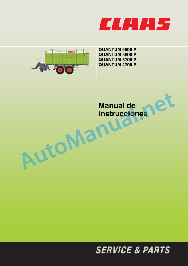
QUANTUM 6800 PQUANTUM 5800 PQUANTUM 5700 PQUANTUM 4700 P
1 Regarding this instruction manual
1.1 Information regarding the instruction manual
1.1.1 Validity of the manual
1.1.2 Information regarding the instruction manual
1.1.3 Symbols and indications
1.1.4 Optional equipment
1.1.5 Qualified specialized workshop
1.1.6 Maintenance instructions
1.1.7 Information regarding warranty
1.1.8 Technical instructions
1.1.9 Spare parts and technical questions
2 Security
2.1 Proper application of the machine
2.1.1 Proper machine application
2.1.2 Logically foreseeable inappropriate application
2.2 Safety instructions
2.2.1 Instruction manual and other sources of information
Meaning of the instruction manual
2.2.2 Qualification of personnel and organization
Requirements of all people who work with the machine
2.2.3 Danger to children
Children in danger
2.2.4 Machine coupling
Tractor coupling with machine
2.2.5 Modifications to the machine
Construction modifications
2.2.6 Supplementary equipment and spare parts
Supplementary equipment and spare parts
2.2.7 Jobs and accompanying persons
Control of the machine running
Accompanying instructors during work
2.2.8 Perfect technical condition
Use only after proper delivery inspection
Use only after correct commissioning
Perfect technical condition of the machine
Danger due to machine failure
Comply with technical limit values
2.2.9 Danger zones
Danger zones
Stand between the machine and the tractor
Objects that are thrown
Danger with connected drive
Danger of injury when taking power
Danger of injury to the cardan shaft
Danger due to coasting parts
2.2.10 Protection devices
Keep protective devices operational
2.2.11 Personal protective equipment
personal protective equipment
Wear appropriate clothing
2.2.12 Safety symbols
Keep safety decals legible
2.2.13 Road safety
Dangers when driving on the road and in the countryside
Danger of tipping over
Prepare the machine for road use
Park the machine safely
Unsupervised parking of the tractor with the machine
Keep the machine free of foreign objects
2.2.14 Consumables
Unsuitable consumables
Safe handling of consumables and auxiliary materials
Environment and waste disposal
2.2.15 Sources of danger in the machine
Electrical shock from electrical equipment
Vibrations can cause health damage
Liquids under pressure
Air under presure
Hot surfaces
2.2.16 Dangers when getting on and off
Get on and off safely
2.3 Safety instructions on the machine
2.3.1 Information on graphic danger symbols
2.3.2 Position of warning symbols
3 Machine Description
3.1 Summary and operation
3.1.1 Machine overview
3.1.2 Machine operation
Loading and silage trailer operating mode
3.2 Optional equipment
3.2.1 COMMUNICATOR II*
3.2.2 ISOBUS connection cable*
3.2.3 Union fork*
3.2.4 Cargo space lighting*
3.2.5 Battery cable*
3.2.6 Order printer for ISOBUS
3.2.7 Control line of the Load-Sensing* hydraulic system
3.2.8 Drawbar extension for hitch hitch*
3.2.9 Triple hydraulic connection for the tractor
3.3 Identification plates and identification numbers
3.3.1 Spare parts and technical questions
3.3.2 Machine identification plate
3.3.3 Lance identification plate
3.3.4 Shooting eyelet identification plate
3.4 Machine information
3.4.1 Adhesives on the machine
4 Control and display instruments
4.1 External control cell
4.1.1 Cutting table
4.2 Control elements
4.2.1 Parking brake
4.2.2 Air brake
4.2.3 Blades
4.2.4 Air Suspension Advance Device Rotary Slide Valve*
4.3 ISOBUS Terminal
4.3.1 Screen
4.3.2 Menu bar
4.3.3 Data field
4.3.4 Status bar
4.3.5 Softkey
4.3.6 Softkey – summary
Menu
Submenu
Submenu
Submenu
Submenu
Menu
Submenu
Submenu
Menu
Submenu
Submenu
4.3.7 Program version
5 Technical data
5.1 QUANTUM 6800P
5.1.1 Measurements
5.1.2 Weights
5.1.3 Pickup
5.1.4 Cutting mechanism
5.1.5 Tire air pressure
5.1.6 Requirements for the tractor
5.1.7 Electrical installation
5.1.8 PTO speed
5.1.9 Acoustic intensity level
5.1.10 Lubricants
5.2 QUANTUM 5800P
5.2.1 Measurements
5.2.2 Weights
5.2.3 Pickup
5.2.4 Cutting mechanism
5.2.5 Tire air pressure
5.2.6 Requirements for the tractor
5.2.7 Electrical installation
5.2.8 PTO speed
5.2.9 Acoustic intensity level
5.2.10 Lubricants
5.3 QUANTUM 5700P
5.3.1 Measurements
5.3.2 Weights
5.3.3 Pickup
5.3.4 Cutting mechanism
5.3.5 Tire air pressure
5.3.6 Requirements for the tractor
5.3.7 Electrical installation
5.3.8 PTO speed
5.3.9 Acoustic intensity level
5.3.10 Lubricants
5.4 QUANTUM 4700P
5.4.1 Measurements
5.4.2 Weights
5.4.3 Pickup
5.4.4 Cutting mechanism
5.4.5 Tire air pressure
5.4.6 Requirements for the tractor
5.4.7 Electrical installation
5.4.8 PTO speed
5.4.9 Acoustic intensity level
5.4.10 Lubricants
6 Preparation of the machine
6.1 Turn off the machine and secure it
6.1.1 Turn off the machine and secure it
6.2 Assemble the machine
6.2.1 Supply package summary
6.2.2 Assemble onboard wall supplements
6.2.3 Assembling onboard wall supplements
6.2.4 Mount the cardan shaft on the machine
6.2.5 Connect the ISOBUS cable*
6.2.6 Mount optional equipment
6.3 Access to jobs and maintenance positions
6.3.1 Access and leave the cargo space
6.4 Adapt the tractor
6.4.1 Hooking device
6.4.2 Install the coupling for forced steering*
6.4.3 Adapt the tractor’s pneumatic brake equipment
6.4.4 Assemble COMMUNICATOR II*
6.4.5 Mount OPERATOR*
6.5 Adapt the machine
6.5.1 Adapt the hydraulic system
Open hydraulic system (standard system)
Closed hydraulic system (constant pressure or Load Sensing)
Connect the Load Sensing control line
6.5.2 Adjusting the hydraulic articulated drawbar
Hydraulic articulated drawbar with labeled pivot lower hitch
Hydraulic articulated drawbar – hitch with pull eye
Anti-twist insurance
Adjust the piston rod
6.6 Hooking the machine to the tractor
6.6.1 General instructions
6.6.2 Connect the cable for advance lighting
6.6.3 Connect COMMUNICATOR II*
On tractors without ISOBUS female plug
On tractors with ISOBUS female plug
6.6.4 Connect OPERATOR*
6.6.5 Attach the hydraulic hoses
Open hydraulic system or closed hydraulic system without control line Load Sensing:
Closed hydraulic system (Load Sensing) with Load Sensing control line:
Power-beyond box:
6.6.6 Hooking the lance with the shooting eye
6.6.7 Attach the drawbar with the labeled lower pivot hitch
6.6.8 Engage forced steering*
Basic regulation
Attach the drawbar
Adjusting the forced steering crash protection
Adjust the gear in a straight line
Check hydraulic pressure
Adjust hydraulic pressure
6.6.9 Check the length of the cardan shaft
Cardan shaft – shortest operating position
Cardan shaft – longest operating position
6.6.10 Adapt the length of the cardan shaft
6.6.11 Assemble the cardan shaft
6.6.12 Adjust the drawbar
6.6.13 Connect the pneumatic brake*
ABS pneumatic brake system*
ABS function control
6.6.14 Connect hydraulically operated brake*
6.6.15 Connect break brake*
6.6.16 Place the support leg upwards
6.6.17 Release the parking brake
6.6.18 Remove shims
6.7 Uncoupling the machine from the tractor
6.7.1 Warnings to take into account
6.7.2 Fit with shims
6.7.3 Set the parking brake
6.7.4 Remove the support leg
6.7.5 Dismantle the cardan shaft
6.7.6 Disengaging forced steering*
Disengage the drawbar
6.7.7 Disengage the drawbar with the labeled lower pivot hitch
6.7.8 Unplug the cable for the forward lighting
6.7.9 Unplug COMMUNICATOR II*
On tractors without ISOBUS female plug
On tractors with ISOBUS female plug
6.7.10 Unplug OPERATOR*
6.7.11 Uncouple the hydraulic hoses
6.7.12 Disengaging the pneumatic brake
ABS pneumatic brake system*
6.7.13 Disengage hydraulically operated brake*
6.7.14 Disengage the break brake*
6.8 Load the machine and tie it down
6.8.1 Load the machine and tie it down
7 Management
7.1 Driving with the self-loading trailer
7.1.1 Check before the trip
7.1.2 Activate the hydraulic drawbar suspension
7.1.3 Activate the air suspension*
7.1.4 Maneuvering the machine with a tractor without pneumatic brake equipment
7.1.5 Lock the tracking axis
7.2 Driving on the road
7.2.1 General instructions
7.2.2 Types of license required for Germany
7.2.3 Documentation that must be carried
7.2.4 Modifications to the machine
7.2.5 Registration obligation and signage obligation
7.2.6 Regular checks under art. 29 StVZO
7.2.7 Driving on public roads
7.2.8 Work focuses
7.3 Adjust before loading
7.3.1 Adjust before loading
7.3.2 Adjust the working height of the pickup
7.3.3 Adjust the roller distributor
7.3.4 Adjust the retaining plate
7.4 loading the trailer
7.4.1 Fill the cargo space evenly
7.5 Unload the trailer
7.5.1 Open the tailgate
7.6 ISOBUS control
7.6.1 Description
General indications
7.6.2 Explanation of ISOBUS terms
7.7 ISOBUS menu structure
7.7.1 Information on menu structure
7.7.2 Main menu
7.7.3
7.7.4 Menu
7.7.5 Menu
7.8.1 Before turning on the terminal
7.8.2 Turn on the terminal
7.8.3 Start the control program
7.8.4 Turn off the terminal
7.9 Open ISOBUS menus
7.9.1 Change main menu
7.9.2 Change submenu
7.9.3 Leave the submenu
7.10 ISOBUS transport
7.10.1 Activate transport position
7.10.2 Activate transport position
7.10.3 Raising and lowering the articulated drawbar
7.10.4 Activate drawbar suspension
7.10.5 Lock and unlock the tracking steering axis
7.10.6 Turning the work lighting on and off*
7.11 ISOBUS loading – automatic handling
7.11.1 Select submenu
7.11.2 Lift to headland position
7.11.3 Lowering to working position
7.11.4 Conveyor bottom control in the
Torque gauge (M)
Automatically connect and disconnect the conveyor floor drive
Adapt the threshold value
7.11.5 Briefly connect the conveyor base
7.11.6 Raise and lower the pickup
7.11.7 Clear conveyor channel jams
7.11.8 Fill level indication*
7.11.9 Message
7.12 ISOBUS loading – manual operation
7.12.1 General instructions
7.12.2 Select submenu
7.12.3 Manually load the machine
7.12.4 Open and close the cutting table
Open the cutting table
Close the cutting table
7.12.5 Open and close the cutting tray with the external control cell
Fully open the cutting table
Completely close the cutting bottom
7.12.6 Increase and reduce the speed of the conveyor bottom
7.12.7 Reverse the drive of the conveyor bottom
7.12.8 Finish
7.13 ISOBUS download – automatic handling
7.13.1 Select submenu
7.13.2 Connecting and disconnecting the conveyor floor drive
7.13.3 Increase and decrease the speed of the conveyor bottom
7.13.4 Finish
7.14 ISOBUS Download – manual operation
7.14.1 General instructions
7.14.2 Select submenu
7.14.3 Manually unload the machine
7.14.4 Open and close the tailgate
Open the tailgate
Close and lock the tailgate
7.14.5 Finish
7.15 ISOBUS settings
7.15.1 General instructions
7.15.2 Submenu
Modify the threshold value
Modify the speed of the conveyor bottom
7.15.3 Connecting and disconnecting the silage additives input*
7.15.4 Clear maintenance alarm
7.16 ISOBUS adjustment of the articulated drawbar
7.16.1 Submenu
7.16.2 Change the positions of the articulated drawbar
7.17 ISOBUS order processing
7.17.1 Display order data
Select job
Order counters
Independent order counters
7.17.2 Connecting and disconnecting data input
7.17.3 Create job
Enter the designation for the order
7.18 ISOBUS information
7.18.1 General instructions
7.18.2
7.18.3 Clear the error message
7.19 ISOBUS auxiliary function (AUX)
7.19.1 Available functions
7.19.2 Example of use
7.20 ISOBUS Drive options – Fendt
7.20.1 Use the tractor terminal
7.20.2 Terminal Tractor and Joystick
7.20.3 Use COMMUNICATOR II* and joystick
7.21 ISOBUS basic settings (initiation)
7.21.1 General instructions
7.21.2 Open submenu
7.21.3 Learn end stops
Error learning end stops
8 Incident and solution
8.1 Emergency management
8.1.1 Work steps before emergency handling
8.1.2 Manually operate the hydraulic valves
8.2 ISOBUS error indications
8.2.1 Alarm messages
8.2.2 Sensor error
8.2.3 General faults
8.2.4 Error code table
9 Maintenance
9.1 Maintenance instructions
9.1.1 General instructions
9.1.2 Screws
9.1.3 Greasing
9.1.4 Brakes
9.1.5 Wheels
9.1.6 Pipes, tubes and hoses
9.1.7 Electrical equipment
9.1.8 Pressurized air and water
9.1.9 Prevention against burns
9.1.10 Oil
9.1.11 Fire and explosion prevention
9.2 Summary of maintenance intervals
9.2.1 Before harvest
9.2.2 After the first 10 hours of service
9.2.3 After the first 50 hours of service
9.2.4 Every 8 hours of service or daily
9.2.5 Every 20 hours of service
9.2.6 Every 50 hours of service
9.2.7 Every 100 hours of service
9.2.8 Every 250 hours of service
9.2.9 Every 500 hours of service or annually
9.2.10 Every 1000 hours of service or every 2 years
9.2.11 Every 5 years
9.2.12 After harvest
9.3 General maintenance work
9.3.1 Clean the machine
9.3.2 Maintain the machine
9.3.3 Check the fixing material
9.3.4 Eliminate crop remains
9.4 Gearbox
9.4.1 Check the tightness of the gear
9.4.2 Check the main gear oil level
9.4.3 Change main gear oil
9.4.4 Check the rotor gear oil level
QUANTUM 6800P / 5800P
QUANTUM 5700P / 4700P
9.4.5 Change rotor gear oil
QUANTUM 6800P / 5800P
QUANTUM 5700P / 4700P
9.4.6 Check the oil level of the conveyor bottom gear
Conveyor bottom gear
Conveyor bottom gear with two-phase motor
9.4.7 Change the conveyor bottom gear oil
Conveyor bottom gear with two-phase motor
9.5 Clutch
9.5.1 General instructions
9.5.2 Check the overload clutch
Cardan shaft overload clutch
9.6 Cardan shaft
9.6.1 Perform cardan shaft maintenance
9.6.2 Remove and install the cardan shaft protection
9.7 Chassis
9.7.1 Check tire air pressure
9.7.2 Retighten the wheel nuts
9.7.3 Change a wheel
9.7.4 Check the steering axle pneumatic spring
9.7.5 Check the air suspension*
9.8 Brake
9.8.1 Carry out a visual check of the brake equipment
9.8.2 Carry out a test of the operation of the brake equipment
9.8.3 Drain water from the compressed air tank*
9.8.4 Clean the pipe air filter*
9.8.5 Check and readjust the piston stroke of the brake cylinder of the pneumatic brake equipment
9.8.6 Check the ABS pneumatic brake system*
9.9 Forced steering
9.9.1 General instructions
9.9.2 Fill and purge forced direction*
Fill the hand pump
Bleed the steering cylinder
Bleed control cylinder
9.9.3 Adjust the stroke of the control cylinder
Extend control cylinder
Pick up the control cylinder
9.10 Drives
9.10.1 Perform chain maintenance
9.10.2 Retension drive chains
9.10.3 Tension the pickup drive chain
9.11 Hydraulic installation
9.11.1 Carry out maintenance on the hydraulic installation
9.11.2 Check the hydraulic hoses
9.11.3 Change the hydraulic oil filter
9.11.4 Check the pressure accumulator
9.12 Electrical and electronic system
9.12.1 Control lighting
9.12.2 Adjust the Reed switch
9.13 Pickup
9.13.1 Check the rollers
9.14 Knife box
9.14.1 Remove blades
9.14.2 Check the blades
9.14.3 Assemble blades
9.14.4 Adjust the pretensioning of the blades
9.14.5 Adjust the cutting table
9.14.6 Adjust the drainer box
9.14.7 Clean the cutting table
9.15 Conveyor bottom
9.15.1 Check the feed blades
9.15.2 Tension the conveyor bottom chains
9.16 Assembly parts
9.16.1 Check the headlights
9.16.2 Check the shims
9.17 Greasing scheme
9.17.1 Grease the lubrication points every 8 hours of service
9.17.2 Grease the lubrication points every 20 hours of service
9.17.3 Grease the lubrication points every 100 hours of service
10 Decommissioning and waste disposal
10.1 General information
10.1.1 Decommissioning and waste disposal
11 EC declaration of conformity
11.1 QUANTUM 6800P / 5800P / 5700P / 4700P
11.1.1 EC declaration of conformity
12 Technical dictionary and abbreviations
12.1 Terms and explanations
12.1.1 Abbreviations
12.1.2 Technical vocabulary
00 0294 706 1.pdf:
1 Machine overview
2 Introduction
Introduction
Validity
4 Prologue
To take into special account
Identification plate
Circulation on public roads
Circulation permit
Driving on public roads
License plate
Regular checks under art. 29 StVZO
5 Security measures
Use in accordance with the intended standards
Warning and danger signs
General safety and accident prevention rules
PTO shaft operation
Hydraulic system
Wheels/tyres, bolted joints
Maintenance
Noise level
Safety decals with warning symbols
6 Technical data
QUANTUM 6800P
QUANTUM 5800P
QUANTUM 5700P
QUANTUM 4700P
7 Assembly
Mounting
QUANTUM 6800P / 5800P / 5700P
QUANTUM 4700P
Docking the machine for the first time
8 Before start-up
Check and observe before commissioning!
Hydraulic articulated lance
Shooting eyelets
Hydraulic articulated drawbar – Hitch coupling
Lance height adjustment
Engage forced steering (additional equipment)
Basic setting
Adjust forced steering start protection
Adjust forced steering
Check/adjust hydraulic pressure
articulated axle
Articulated axle adjustment
Articulated shaft with CC clamping cone lock
Disengage
tractor drawbar
Electric system
Control panel
Driving lighting
ABS pneumatic brake system
ABS operation check
Hydraulic system
Open hydraulic system (standard system)
Closed hydraulic system
Take Power – beyond
Standard steering axle hydraulic connection (Additional equipment, only available ex factory)
Adjust the flow rate in the hydraulic system control block
Support leg
After coupling the self-loading trailer
Stopping the self-loading trailer
Pneumatic brake system
Double pipe system
Maneuvering tractor vehicles without a pneumatic brake system
Hydraulic brake
Hydraulic emergency brake
Connection
Parking break
Apply the brake
Release the brake
Entry hatch (QUANTUM 6800 P / 5800 P only)
Disengage
Self-loading trailer with pneumatic brake system
Self-loading trailer with hydraulic brake
Self-loading trailer with ABS pneumatic brake system
Before transportation
Hydraulic drawbar suspension (additional equipment, only available ex factory)
Activate the drawbar damping
Road walking
9 Handling
Brief instructions
Discharge
articulated lance
Control witnesses
Two-phase motor (Additional equipment, only available from the factory)
Lower/raise the Pick-up
Preset the working height of the Pick-up
Roller tamper (QUANTUM 6800 P / 5800 P)
Retainer (QUANTUM 5700 P / 4700 P)
Open/close the knife box
Connect the friction bottom – Fill the cargo space
Discharge
Open the tailgate
Empty the cargo compartment
Two-phase friction bottom motor (Additional equipment, only available from the factory)
Close the tailgate
Cargo space lighting
Putting the self-loading trailer into service
General charging process
After use
Standard steering axle (Additional equipment, only available ex factory)
Standard steering axle lock
Standard steering axle release
Emergency management
Additional equipment
Tractor electrical system power supply
Control panel extension cable
Load-Sensing Hydraulic System Control Pipe
Lance extension for Hitch coupling (M01/0010)
Hydraulic connection for tractor (R03/0070)
Insert Fork Kit
10 Maintenance
Important maintenance instructions
Wheels / tires
Brakes and axles
Pneumatic brake system
Hydraulic system
Protection devices
Brakes and axles
Pneumatic brake system
ABS pneumatic brake system
Bleed the pressurized air tank of water
Pipes air filter
Clean the filter element
Disassembled pipe air filter
Brake adjustment – Check brake cylinder piston stroke
Brake force regulator
brake linings
Forced direction
Fill/bleed forced direction
Bleed the steering cylinder
Bleed control cylinder
Adjust control cylinder stroke
Extend control cylinder
Pick up the control cylinder
Adjust the operating pressure of the forced steering
Cutting mechanism
Blade change
Disassembly of the blades
Blade assembly
Blade box adjustment
Adjust the scraper box
main gear
QUANTUM 6800 P / 5800 P (Transmission – Product no.: 0973 300.0)
QUANTUM 5700 P / 4700 P (Transmission – Product no.: 0972 140.0)
Purge valve
Friction bottom gear
Friction bottom gear with two-phase motor
QUANTUNM 6800 P / 5800 P / 5700 P (Drive shaft ø 45 mm)
QUANTUM 4700 P (Drive shaft ø 40 mm)
rotor gear
QUANTUM 6800 P / 5800 P (Transmission – Product no.: 0973 301.1)
QUANTUM 5700 P / 4700 P (Transmission – Product no.: 0973 492.0)
Retensioning of drive chains
Tension the Pick-up drive chain
Friction bottom chains
Friction bottom chains (up to year of manufacture 2006)
Friction bottom chains (from year of manufacture 2007)
Pawl Clutch
articulated axle
Air suspension
Lifting and lowering device for air suspension axles
Electric system
Adjusting Reed Switches
Hydraulic system
Change the pressure filter
pressure accumulator
Flexible hydraulic system pipes
Pressure gas spring
Undercarriage
Wheel change
Maintenance and lubrication openings
Protection devices
Screwed joints
Union elements
Cleaning and entertainment
Daily cleaning
Cservation during winter
Lubricants table
Grease points
11 Greasing scheme
Security measures
Lubricants
John Deere Repair Technical Manual PDF
John Deere Repair Technical Manual PDF
John Deere Transmission Control Unit Component Technical Manual CTM157 15JUL05
John Deere Repair Technical Manual PDF
John Deere Diesel Engines PowerTech 4.5L and 6.8L – Motor Base Technical Manual 07MAY08 Portuguese
John Deere Repair Technical Manual PDF
John Deere Repair Technical Manual PDF
John Deere Repair Technical Manual PDF
John Deere Repair Technical Manual PDF
John Deere POWERTECH E 4.5 and 6.8 L Diesel Engines TECHNICAL MANUAL 25JAN08
John Deere Repair Technical Manual PDF


