Claas Quantum 6800-4500 Gt P (615) Loader Wagons Technical System ES
$150.00
- Model: Quantum 6800-4500 Gt P (615) Loader Wagons
- Type Of Manual: Technical System
- Language: ES
- Format: PDF(s)
- Size: 16.4 MB
File List:
00 0295 557 0.pdf
00 0297 458 4.pdf
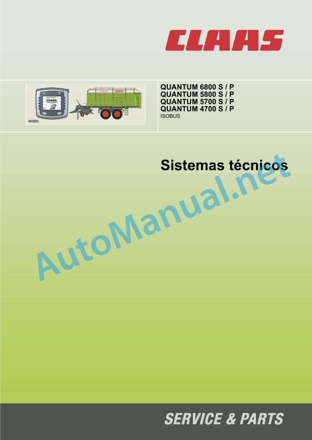
00 0295 557 0.pdf:
1 Global hydraulic system
QANTUM 6800 S – 4700 S hydraulic connection diagram
Global wiring diagram
Denominations
QANTUM 6800 P – 4700 P hydraulic connection diagram
Global wiring diagram
Denominations
QUANTUM 6800 – 4700 S main valve block
QUANTUM 6800 – 4700 P main valve block
Denominations
Location of hydraulic system components
Individual components
2 Electrical installation
Electrical connection diagram
Graphic (DIN A3)
Denominations
Self-loading trailer module A108
Representation
Occupation of the sockets
Module A108 – self-loading trailer
Cutting bottom position sensor (B067)
Graphic representation
Function
Adjustment
Table of measured values
Rev speed sensor t.d.f. tree rear (B142)
Graphic representation
Function
Adjustment
Table of measured values
Traction force sensor (B144)
Graphic representation
Function
Adjustment
Table of measured values
Tailgate opening angle sensor (B206)
Graphic representation
Function
Adjustment
Table of measured values
Pick-up position sensor (B263)
Graphic representation
Function
Adjustment
Table of measured values
Drawbar position sensor (B264)
Graphic representation
Function
Adjustment
Table of measured values
Covered load sensor (B265)
Graphic representation
Function
Adjustment
Table of measured values
100% full load warning sensor (B266)
Graphic representation
Function
Adjustment
Table of measured values
Rev speed sensor metering roller (B267)
Graphic representation
Function
Adjustment
Table of measured values
Harvest load level sensor (B268)
Graphic representation
Function
Adjustment
Table of measured values
Alphabetical index
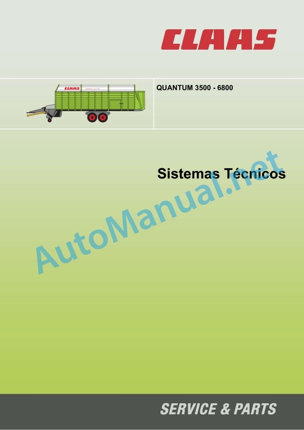
00 0297 458 4.pdf:
QUANTUM Technical Systems 3500 – 6800
Chapters
1 Technical data
1.0 QUANTUM 2500K, 2500P, 3500K, 3500P, 3800K, 3800P
1.1 QUANTUM 3500K, 3500P, 3500S, 3800K, 3800P, 2500K, 2500P
1.2 QUANTUM 5500 S-18, 5500 S-16, 5500 S, 4500 S, 6800 S
1.3 QUANTUM 6800 P, 6500 P, 5500 P-18, 5500 GT, 5500 P, 4500 P
3 Management
1.0 QUANTUM 2500K, 2500P, 3500K, 3800K, 3800P, 3500S
1.1 Key set – instructions
1.2 Management
2.0 QUANTUM 4500 S / 5500 S / S-16 / S-18 / 6800 S
2.1 Key set – instructions
2.2 Management
3.0 QUANTUM 4500 P / 5500 P / 5500 P-16 / 5500 P-18 / 5500 GT / 6800 P
3.1 Key set – instructions
3.2 Management
10 Brakes
1.0 Connection diagrams – pneumatic brakes
1.1 QUANTUM 5500P/S-16 40km/h, 16th, (steering axle)
1.2 QUANTUM 2500 K/P, 3500P/S/K, 3800K/P, 4500S/P 40 km/h (steering axle)
1.3 5500P/S 40 km/h, 13 to, (steering axle)
1.4 5500P-18/S – 18, 60 km/h
1.5 5500P/S 80km/h (ABS)
1.6 Air suspension with leveling valve
1.7 5500 P/S 50/60 km/h
1.8 5500 S, 40/60 km/h
2.0 Settings
2.1 Diaphragm cylinder
2.2 Adjust the linkage play plate
2.3 Brake intensity regulator (ALB)
2.4 Air suspension
11 Hydraulic installation
1.0 LS Pump
1.1 Starting position (engine off)
1.2 Low reserve position (low pressure standby)
1.3 A hydraulic control is activated = the LS pump is placed on supply
1.4 Constant flow
1.5 Reduce flow
1.6 Maximum pressure limitation (pressure limiting valve function)
1.7 Connect the self-loading trailer (hydraulic supply)
2.0 QUANTUM 3500K / 3800K / 3500P / 3500S
2.1 3500K, 2500K, 3800K
2.2 3500P, 2500P, 3800P
2.3 3500S
3.0 QUANTUM 4500S / 5500S / S-16 / S-18 / 6800S
3.1 Scheme
3.2 Connection diagram
3.3 Control block
3.4 4/3-way electromagnetic valve (cutting table, articulated drawbar raise/lower)
3.5 3/3-way solenoid valve (open/close tailgate)
3.6 Valve block (Pick-up and metering roller)
3.7 Switching cylinder for the Pick-up and for the metering rollers
3.8 DANFOSS OMR 125 oil motor for friction bottom (single level motor)
3.9 2-level motor
3.10 3-way flow regulating valve for lateral conveyor belt
3.11 4/3-way solenoid valve (cross conveyor belt)
3.12 3/2-way solenoid valve (transverse conveyor belt) QUANTUM S
4.0 QUANTUM 4500P / 5500P / 5500 P-16 / 5500 P-18 / 5500GT /_x000B_6500P / 6800P
4.1 Connection diagram
4.2 Function
4.3 Circulation valve with pressure limiting valve
4.4 4/3-way electromagnetic proportional valve
4.5 4/3-way solenoid valve
4.6 2/2-way solenoid valve (seat valve)
4.7 DANFOSS OMR 125 Oil Engine
4.8 Failures and solutions
4.9 Locking cylinder for tracking axis
5.0 QUANTUM 6800
5.1 Forced steering
12 Electrical installation
1.0 QUANTUM 2500K, 2500P, 3500K, 3500P, 3500S, 3800K, 3800P
1.1 Connection diagram 3500 K, 3800 K, 2500 K
1.2 Connection diagram 3800 P, 3500 P, 2500 P
1.3 Connection diagram 3500 S
1.4 Contact vibrator amplifier – chopper SC-2000-U
1.5 Lighting
2.0 QUANTUM 4500 S / 5500 S / S-16 / S-18 / 6800 S
2.1 Connection diagram
2.2 Diagnosis
2.3 Printed circuit board (A) QUANTUM S
2.4 Reed switch adjustment
2.5 Dual microswitch (dip)
2.6 QUANTUM S Lighting
3.0QUANTUM4500P / 5500P / 5500P-16 / 5500P-18 / 5500GT / _x000B_6500P / 6800P
3.1 Connection diagram
3.2 QUANTUM P distribution box
3.3 Failures and solutions
3.4 QUANTUM P lighting
0297 458.4
John Deere Repair Technical Manual PDF
John Deere Repair Technical Manual PDF
John Deere Transmission Control Unit Component Technical Manual CTM157 15JUL05
John Deere Repair Technical Manual PDF
John Deere Diesel Engines PowerTech 4.5L and 6.8L – Motor Base Technical Manual 07MAY08 Portuguese
John Deere Repair Technical Manual PDF
John Deere Repair Technical Manual PDF
John Deere Repair Technical Manual PDF
John Deere 16, 18, 20 and 24HP Onan Engines Component Technical Manual CTM2 (19APR90)
John Deere Repair Technical Manual PDF
John Deere 18-Speed PST Repair Manual Component Technical Manual CTM168 10DEC07
John Deere Repair Technical Manual PDF
John Deere Application List Component Technical Manual CTM106819 24AUG20


