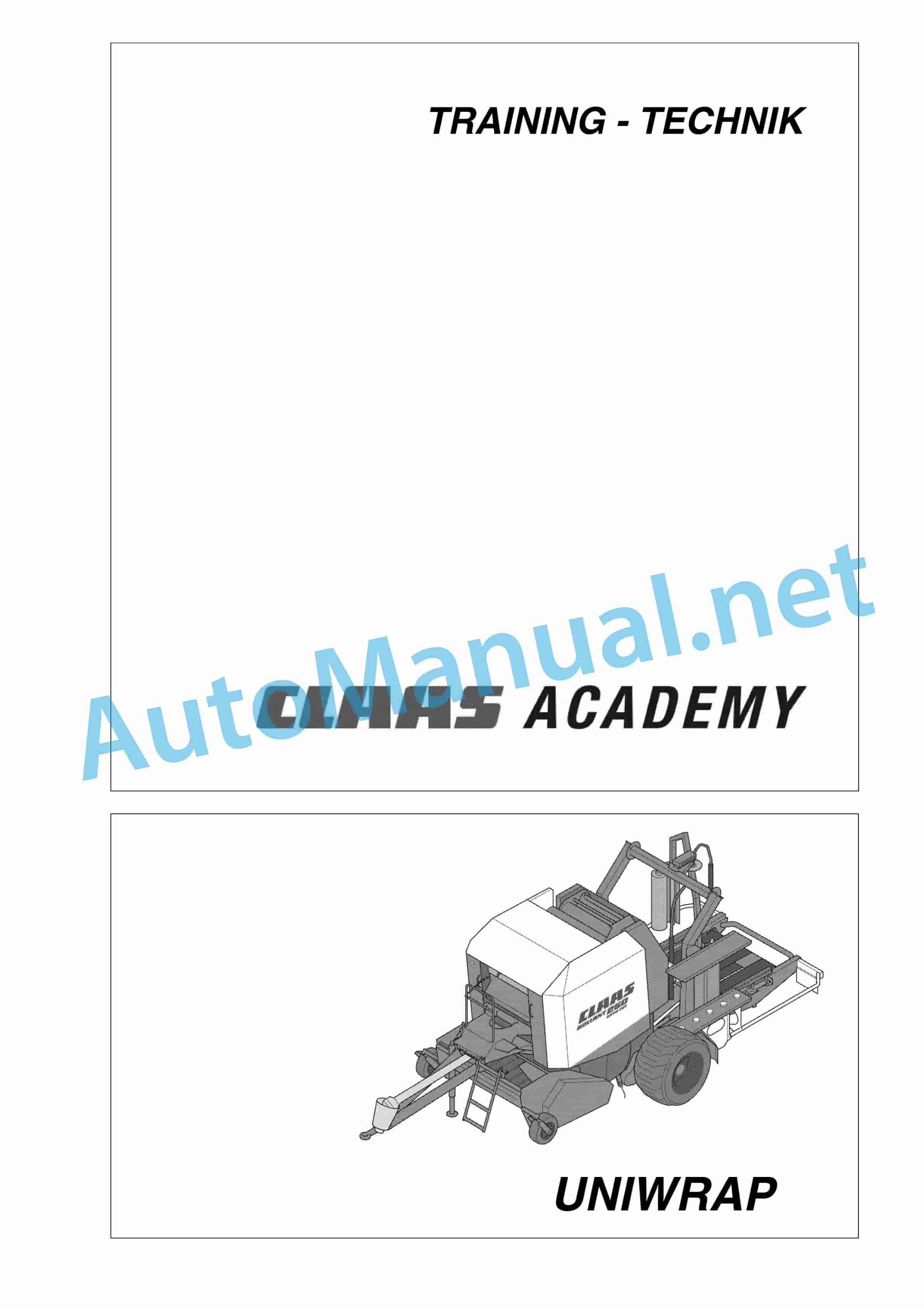
Claas ROLLANT 250 255 UNIWRAP (726) Baler Technical System DE
$150.00
- Model: ROLLANT 250 255 UNIWRAP (726) Baler
- Type Of Manual: Technical System
- Language: DE
- Format: PDF(s)
- Size: 18.9 MB
File List:
– 00 0293 485 0.pdf
– 00 0293 486 1.pdf
– 00 0293 488 0.pdf
– 00 0297 759 2.pdf
00 0293 485 0.pdf
Table of Content:
1 Electric system technology ROLLANT 240/250
2 Structure of electrical circuit diagrams
4 central electrics
4.1 Central electrics Rollant 240/250 Standard
4.2 Central electrics Rollant 250 Comfort
4.3 UNIWRAP central electrics
5 Pin assignment of the modules
5.1 ROLLANT 240/250 Standard
5.2 ROLLANT 240/250 Comfort
5.3 UNIWRAP
6 Circuit diagram assignment of fuses and relays
7 circuit diagrams 01a – 40c
7.1 01a – Main power supply Rollant 240/250 Standard
7.2 01b – Main power supply Rollant 250 Comfort
7.3 01c – Main power supply Rollant 250 Comfort for UNIWRAP
7.4 01d – Main power supply UNIWRAP
7.5 04a – Circulation check valve (with central electrics) Rollant 250 Comfort
7.6 04b – Circulation check valve Rollant 250 Comfort for UNIWRAP
7.7 04c – UNIWRAP circulation check valve
7.8 05a – Terminal Rollant 250 Comfort
7.9 05b – Terminal UNIWRAP to mach. no. 726 00 130
7.10 06a – CAN bus, power supply module Rollant 240/250 Standard
7.11 06b – CAN bus, power supply module Rollant 250 Comfort
7.12 06c – CAN bus, power supply module Rollant 250 Comfort for UNIWRAP
7.13 06d – CAN bus, power supply module UNIWRAP up to mach. no. 72900130
7.14 06e – CAN bus, power supply module UNIWRAP from mach. no. 72900131
7.15 07a – Rotocut Rollant 240/250 Standard
7.16 07b – Rotocut Rollant 250 Comfort / Comfort for UNIWRAP
7.17 11a – Binding release Rollant 240/250 Standard
7.18 11b – Binding release Rollant 250 Comfort / Comfort for UNIWRAP
7.19 12a – Open / close tailgate Rollant 250 Comfort / Comfort for UNIWRAP
7.20 19a Loading / unloading bales UNIWRAP
7.21 20a – Raise and lower pick-up – Rollant 250 Comfort / Comfort for UNIWRAP
7.22 21a – Rotate wrapping arm – UNIWRAP
7.23 22a – Open/close film scissors, monitoring film tear – UNIWRAP
7.24 32a – Rear light, position light (with central electrics)
7.25 40a additional sockets
7.26 40b additional sockets
7.27 40c additional sockets
8 wire harnesses
8.1 Wiring harness A Part 1 (Rollant 250 Standard)
8.2 Wiring harness A Part 2 (Rollant 250 Standard)
8.3 Wiring harness B Part 1 (Rollant 250 Comfort / Rollant 250 Comfort for UNIWRAP)
8.4 Wiring harness B Part 2 (Rollant 250 Comfort / Rollant 250 Comfort for UNIWRAP)
8.5 Wiring harness B Part 3 (Rollant 250 Comfort / Rollant 250 Comfort for UNIWRAP)
8.6 Wiring harness C (Rollant 2504 central electrics
4.1 Central electrics ROLLANT 254/255 Standard
4.2 Central electrics ROLLANT 254/255 Comfort when equipped with
4.3 Central electrics with CCU (Claas Control Unit) at Ausrstun
4.4 Central electrics UNIWRAP
5 Pin assignment of the modules
5.1 Module A23 ROLLANT 254/255 Standard
5.2 Module A23 1 ROLLANT 254/255 Comfort when equipped with CC
5.3 Module A23 2 ROLLANT 254/255 Comfort when equipped with CC
5.4 Module A22 50nicator
7.5 01e – Main power supply ROLLANT 254 / 255 Comfort for UNIWRAP with Communicator
7.6 01f – Main power supply UNIWRAP
7.7 04a – Circulation check valve ROLLANT 254/255 Comfort – with CCT
7.8 04b – Circulation check valve ROLLANT 254/255 Comfort for UNIWRAP – with CCT
7.9 04c – Circulation check valve ROLLANT 254/255 Comfort – with Communicator
7.10 04d – Circulation check valve ROLLANT 254 / 255 Comfort for UNIWRAP with Communicator
7.11 04e – Circulation check valve UNIWRAP
7.12 05a – Terminal ROLLANT 254/255 Standard
7.13 05b – Terminal ROLLANT 254/255 Comfort – with CCT
7.14 05c- Terminal 254/255 Comfort for UNIWRAP – with CCT
7.15 06a – CAN bus, power supply module ROLLANT 254/255 Standard
7.16 06b – CAN bus, power supply module ROLLANT 254/255 Comfort – with CCT
7.17 06c – CAN bus, 06e – CAN bus, power supply module ROLLANT 255 Comfort for UNIWRAP with Communicator
7.20 06f – CAN bus, power supply module UNIWRAP up to mach. no. 130
7.21 06g – CAN bus, power supply module UNIWRAP from mach. no. 131
7.22 07a – Rotocut 254/255 Standard
7.23 07b – Rotocut ROLLANT 254/255 Comfort / Comfort for UNIWRAP – with CCT
7.24 07c – Rotocut ROLLANT 254/255 Comfort / Comfort for UNIWRAP – with communicator, reversing switch (Z48)
7.25 07d – Rotocut ROLLANT 254/255 Comfort / Comfort for UNIWRAP – with communicator, sensor reversing (B131)
7.26 11a – Binding release 254/255 Standard
7.27 11b – Binding release ROLLANT 254/255 Comfort / Comfort for UNIWRAP – with CCT
7.28 11c – Binding release ROLLANT 254/255 Comfort / Comfort for UNIWRAP – with communicator, tailgate closed switch (Z16)
7.29 11d – Binding release ROLLANT 254/255 Comfort / Comfort for UNIWRAP – with communicator, tailgafort / Comfort for UNIWRAP – with CCT
7.31 12b – Open / close tailgate ROLLANT 254/255 Comfort / Comfort for UNIWRAP – with Communicator
7.32 19a – Loading / unloading bales UNIWRAP
7.33 20a – Raise pick-up lower ROLLANT 254/255 Comfort / Comfort for UNIWRAP – with CCT
7.34 20b – Raise / lower pick-up ROLLANT 254/255 Comfort / Comfort for UNIWRAP – with Communicator
7.35 21a – Turn wrapping arm UNIWRAP
7.36 40a – additional sockets ROLLANT 254/255 Comfort / Comfort for UNIWRAP – with Communicator
8 wire harnesses
8.1 Wiring harness A Part 1
8.2 Wiring harness A part 2
8.3 Wiring harness B part 1
8.4 Wiring harness B part 2
8.5 Wiring harness Braulic system technology UNIWRAP
3 1 Hydraulic circuit diagrams
3.1 1.1 Hydraulic circuit diagram up to machine number: 72600130
3.2 1.2 Hydraulic circuit diagram from machine number: 72600131, with service shut-off valve for tipping body (631)
3.3 1.3 Hydraulic circuit diagram from machine number: 72600531, with flow divider, film clamping scissors (769)
3.4 1.4 Hydraulic circuit diagram from machine number: 72601047, with valve combination (630, 706, 769), without 3-stage throttle (645)
3.5 1.5 Hydraulic circuit diagram from machine number: 72601047, with valve combination (630, 706, 769), with 3-stage throttle (645)
4 2 Application requirements
4.1 2.1 Block circulation check valve (Y77)
4.2 2.2 Connection to the tractor hydraulics
5 3 valve block
5.1 3.1 Valve block, up to machine number: 130
5.2 3.2 Valve block – from machine no. 131, with service shut-off valve for tipping body (631)
6 4 individual components
6.1 4.1 Inlet pressure compensator (763)
6.2 4.2 Circulation check valve (Y77-2)
6.3 4.3 Wrapping arm control unit (Y133)
6.4 4.4 Tipping body control unit (Y135 / Y136)
6.5 4.5 Changing table control unit (Y137 / Y138)
6.6 4.6. Clamping scissors control unit (Y139 / Y140)
6.7 4.7 Quantity controller (630)
6.8 4.8 Pressure relief valve (706)
6.9 4.9 Wrapping arm motor (234)
6.10 4.10 Changing table motor (235)
6.11 4.11 Service tipping body shut-off valve (631)
6.12 4.12 Hydraulic cylinder film clamping scissors (374)
6.13 4.13 Flow divider film clamping scissors (769)
6.14 4.14 Valve block wrapping arm motor (4)
6.15 4.15 3-stage throttle
6.16 4.16 Valve combination (7)
6.17 4.17 Distributor (8)
7 0293 488.0
John Deere Repair Technical Manual PDF
John Deere PowerTech M 10.5 L and 12.5 L Diesel Engines COMPONENT TECHNICAL MANUAL CTM100 10MAY11
John Deere Repair Technical Manual PDF
John Deere 16, 18, 20 and 24HP Onan Engines Component Technical Manual CTM2 (19APR90)
John Deere Repair Technical Manual PDF
John Deere Repair Technical Manual PDF
John Deere Repair Technical Manual PDF
John Deere Parts Catalog PDF
John Deere Harvesters 8500 and 8700 Parts Catalog CPCQ24910 Spanish
John Deere Repair Technical Manual PDF
John Deere 18-Speed PST Repair Manual Component Technical Manual CTM168 10DEC07
John Deere Repair Technical Manual PDF
John Deere DF Series 150 and 250 Transmissions (ANALOG) Component Technical Manual CTM147 05JUN98


