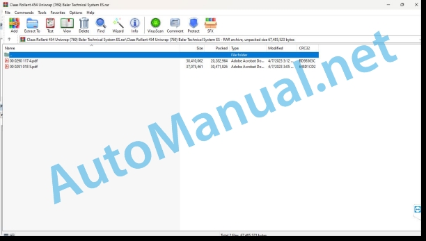
Claas Rollant 454 Uniwrap (769) Baler Technical System ES
$150.00
- Model: Rollant 454 Uniwrap (769) Baler
- Type Of Manual: Technical System
- Language: ES
- Format: PDF(s)
- Size: 48.4 MB
File List:
00 0290 117 4.pdf
00 0291 018 5.pdf
00 0290 117 4.pdf:
ROLLANT 455 / 454 UNIWRAP
Introduction
Safety instructions
Safety measures and danger notices
Manual validity
Machine validity
CCN Explanation
General indications
Electrical regulations
Hydraulic regulations
CCN (CLAAS Component Number)
09 Hydraulic
0920 Valves
Valve block – ROLLANT 455
Valve block – ROLLANT 454
Valve block – bale wrapper
Sectional display of hydraulic block – baler
Hydraulic system protection valve (7190)
Function Description
0980 Hydraulic connection diagram
Hydraulic installation of the baler, ROLLANT 455 UNIWRAP type 750
Hydraulic installation of the baler, ROLLANT 454 UNIWRAP type 769
Baler hydraulic installation, ROLLANT 455 / 454 UNIWRAP type 750 / 769
Oil supply connection diagram
Denominations
Function Description
10 Install. electrical/electronic
1010 Central electrical system
Central electrical system (module A023 – contact box)
Denominations
1012 Modules / sensors
A023 ROLLANT module, A044 Communicator module, A090 terminal module
Module occupancy
Module A023 ROLLANT (CCU)
1080 Electronic connection diagram
Introduction of connection diagrams
Summary of denominations
Name of CLAAS cables
Power supply
Actuator system
sensory system
Communication
Standards
Electrical installation connection diagrams (SCM)
SCM 0 – Communicator connection cable variants
SCM 01 – Main voltage supply (before SI 12337)
SCM 01 – Main voltage supply (after SI 12337)
Function Description
SCM 06 – CAN-BUS, module voltage supply (before SI 12337)
SCM 06 – CAN-BUS, module voltage supply (after SI 12337)
Function Description
SCM 07 – ROTOCUT, cutting bottom
SCM 10 – Baling pressure regulation, MPS regulation
SCM 11 – shot of the bundle
SCM 12 – open/close tailgate
SCM 19 – loading and unloading winding table, tilting platform, slope system
SCM 21 – Wrapping arm
SCM 22 – control of plastic tape breakage, plastic tape scissors
SCM 23 – loading rolls of plastic tape
SCM 29 – Central lubrication system
SCM 31a – Bale wrapper working lighting (up to no. 76900025 / 75000350)
SCM 31b – Bale wrapper working lighting (from no. 76900026 / 75000351)
SCM 32 – lighting
Socket database (chp CLAAS)
Example of key number representation (CHP)
Key number (CHP)
Plug Representation (CHP)
20 Reception of the harvest
2020 Pickup
Function Description
21 Power set
2125 Rotor
Rotor / cutting bottom
Table of measured values
Rotocut cutting device
Valve spool P-A, P-B (7191) with switching
Denominations
Valve spool task (7191) P-A, P-B
ROTOCUT / blades on, off
Denominations
Connected blades function desc.
ROTOCUT / cutting background
Denominations
Cutting bottom function
Cutting bottom position sensor (B067)
Sensor margins (B067)
Sensor adjustment function description (B067)
Rotocut ROLLANT 45X Process Diagrams
Lower the blades, manual
Raise blades, manual
Blade cleaning, automatic
Cutting depth overload adjustment, automatic
Release rotor lock
Open the cutting bottom, manual operation
ROTOCUT DESC, upon reaching the maximum bale diameter
Function: Outer layer of cut bale
Function: Thin outer layer of the uncut bale
Function: Outer thick layer of uncut bale
45 Pressing device
4520 Pressing rollers / reversing rollers
Baling pressure adjustment
Function summary, legend
Baling chamber and rollers
packaging cycle
Valve spool P-A, P-B (7191) with switching
Denominations
Function Description
Tailgate shut-off valve, MPS (7189) with switching
Denominations
Tailgate shut-off valve, MPS (7189) with switching (valve section)
Denominations
Function Description
Baling pressure adjustment
Denominations
Function Description
4535 Oscillation segment
MPS Maximum Pressure System (tilting roller segment)
MPS system pressure regulation
Denominations
Function Description
Sensor adjustment function description (B208)
46 Tying system
4615 Mesh Tying
mesh tying
Table of measured values
Function Description
Mesh brake diagram: adjustment 1.5 turns of mesh
Mesh brake diagram: adjustment 2.5 turns of mesh
Mesh tying process diagram
Sensor adjustment function description (B206)
47 Bale wrapper
4705 Tilting table
Load/unload UNIWRAP bales
Table of measured values
Function Description
Hydraulic bale wrapper block
Connection diagram of the hydraulic installation for raising and lowering the tilting platform
Hydraulic valves raise-lower the tilting platform
Function Description
Tilting platform sensor adjustment
Tilting platform position sensor adjustment (B211)
Adjust bale sensors on the tilting platform (B102)
4715 Packing table
Hydraulic valves raise – lower the winding table
Function Description
Winding table sensor adjustment
Description of the winding table position sensor adjustment function (B210)
4730 Wrapping arm
Bale wrapping process diagram
UNIWRAP bale wrapping
Table of measured values
Function Description
Hydraulic valves, wrap the bale.
Connection diagram of the hydraulic installation, speed adjustment of the hydraulic motors, bale wrapper
Hydraulic valves, speed adjustment of hydraulic motors, bale wrapper
Table of measured values
Function Description
Hydraulic valves: Adjustment of the speed ratio of the wrapping arm with respect to the winding table
Hydraulic connection diagram for adjusting the speed ratio of the wrapping arm with respect to the winding table
Hydraulic adjustment valves for wrapping arm / winding table
Function Description
Average adjustment characteristic:
Hydraulic connection diagram, wrap with plastic tape. Finish the winding process
Wrap hydraulic valves with plastic tape. Finish the winding process
Function Description
LS signal circuit selector
Function Description
Function description modify the winding/overlapping of plastic tape.
Denominations
Description of the function: roll up after a plastic tape break, with a plastic tape.
Denominations
Description of the stop function of the winding table.
Denominations
Description of the stop winding function.
Denominations
Winding arm motor
Denominations
Winding arm sensor adjustment
Sensor adjustment function description (B106)
Switch setting function description (Z091)
Description of the sensor adjustment function (B294) and (B295)
4735 Taper
Plastic tape taper
Plastic Tape Wrapper Sprocket Sets
4745 Plastic tape carrier
Plastic tape boxes
Table of measured values
Function Description
75 Central lubrication
7515 Lubrication/piping equipment
Electric central lubrication system
Table of measured values
Function Description
Diagnosis according to fault codes
Error codes
CLAAS COMMUNICATOR
mesh tying
Electric current circuit
Wrapping machine
CLAAS Medium Terminal
Wrapping machine
Location of components
Hydraulic installation
Location of the components of the hydraulic installation
1001-1999 Oil tank/filter/oil radiator
2001-2999 Pump/motor
3001-3999 Hydraulic Cylinder
5001-5999 Pressure accumulator
6001-6999 Mechanically Actuated Valve
7001-7999 Hydraulic Actuated Valve
9001-9999 Measuring points / indicating instruments
Electrical installation
Location of the components of the electrical installation
To Terminal/modules
B Sensors
and lighting
K Relays
M Motor (electric)
U External control switch
V Electronic parts
X Pluggable connections
and electromagnetic coils
Z Effective value switch
00 0291 018 5.pdf:
ROLLANT 455 / 454with and without UNIWRAP
Introduction
Manual validity
General indications
Important information on safety and dangers
Machine validity
CCN Explanation
General indications
Electrical regulations
Hydraulic regulations
CCN (CLAAS Component Number)
09 Hydraulics
0900 General instructions for the hydraulic installation
External oil supply
Constant current hydraulic installation connection
Function Description
Constant pressure hydraulic system connection
Function Description
Load Sensing connection with Power-Beyond
Function Description
0920 Valves
ROLLANT valve block
ROLLANT 455 valve block
ROLLANT 454 valve block
UNIWRAP valve block
Winding arm valve block
0980 Hydraulic connection diagram
ROLLANT 455 hydraulic connection diagram
ROLLANT 454 hydraulic connection diagram
UNIWRAP hydraulic connection diagram
10 Install. electrical/electronic
1005 Power supply
Main voltage supply
Table of measured values
Function Description
1012 Modules / sensors
Module occupancy
Module occupancy
1030 On-board computer / display devices
COMMUNICATOR and printer connection Electrical installation: COMMUNICATOR and printer connection
COMMUNICATOR version II presentation
Connection
COMMUNICATOR cable variants
Function Description
Cable variant with printer option
Function Description
1080 Electrical connection diagram
Introduction of connection diagrams
Summary of denominations
Name of CLAAS cables
Power supply
Actuator system
sensory system
Communication
Standards
Connection diagrams for the ROLLANT Solo electrical installation
Main voltage supply
CAN bus and module voltage supply, up to 76100306 / 76800120
CAN bus and module voltage supply, from 76100307 / 76800121
BROKEN CUT
Baling pressure regulation, MPS regulation
Triggering of tying and ejecting bales
Open/close tailgate
Machine control
Central lubrication system
Lightning
Connection diagrams for the ROLLANT UNIWRAP electrical installation
Main voltage supply, up to 75001118 / 76900121
Main power supply, from 75001119 / 76900122
CAN bus and module voltage supply, up to 75000891 / 76900068
CAN bus and module power supply, 75000892 – 75001118 / 76900069 – 76900121
CAN bus and module voltage supply, from 75001119 / 76900122
ROTO CUT, up to 75001118 / 76900121
ROTO CUT, from 75001119 / 76900122
Baling pressure adjustment, MPS adjustment, up to 75001118 / 76900121
Baling pressure adjustment, MPS adjustment, from 75001119 / 76900122
Bundling shot, up to 75001118 / 76900121
Bundling shot, from 75001119 / 76900122
Open/close tailgate, up to 75001118/76900121
Open/close tailgate, from 75001119 / 76900122
Tying plastic tape
Load/unload bales, UNIWRAP
Rotate the winding arm, UNIWRAP
Plastic tape scissors and plastic tape breakage control, UNIWRAP
Loading plastic tape rollers, UNIWRAP
Machine control, up to 75001118 / 76900121
Machine control, from 75001119 / 76900122
Central lubrication system, up to 75001118 / 76900121
Central lubrication system, from 75001119 / 76900122
Work lighting
Lightning
Socket database (chp CLAAS)
Example of key number representation (CHP)
Key number (CHP)
Plug Representation (CHP)
1085 Networks
Table of measured values
Function Description
20 Reception of the harvest
2020 Pickup
Function Description
21 Power set
2125 Rotor
Cutting device and cutting floor automation
Table of measured values
Function Description
Adjustment
Diagram of the ROTO CUT process, activating the blades and cleaning blades with active blades
Diagram of the ROTO CUT process, deactivating the blades and cleaning blades with deactivated blades
Diagram of the ROTO CUT process, overload automation and automatic unclogging
ROTO CUT process diagram, uncut bale edge
Diagram of the process opening the cutting bottom
Diagram of the process to close the cutting bottom
Cutting bottom process diagram, automatic unclogging
45 Pressing device
4500 Crimping device
Regulation of baling pressure, MPS and tailgate operation
Table of measured values
Function Description
Graphic: Close the tailgate, add MPS, recharge baling pressure and MPS pressure
Function Description
Graphic: Packing, pressure regulation, tailgate and MPS
Function Description
Graphic: Open the tailgate, take out MPS
Function Description
Adjustment
46 Tying system
4615 Mesh tying / plastic tape tying
mesh tying
Table of measured values
Function Description
Mesh brake diagram without tying plastic tape
Mesh brake diagram with plastic tape tying
Mesh tying process diagram
Tying plastic tape
Table of measured values
Function Description
Plastic tape brake diagram
Diagram of the plastic tape tying process
47 Bale wrapper
4700 Bale Wrapper
UNIWRAP bale wrapping
Table of measured values
Function Description
Function Description
Process diagram 1 wrapping
Process diagram 2 wrapping
Adjustment
60 Deposit the material / deposit the straw
6040 Bale unloading
Bale ramp (only without UNIWRAP)
Function Description
Adjustment
75 Central lubrication
7505 Container, pump
Electric central lubrication system
Table of measured values
Function Description
7515 Lubrication/piping equipment
Chain lubrication
Function Description
Verification
92 Diagnosis
9210 Machine Error Codes
Fault indications on the control terminal
Location of components
Electrical installation
To Terminal/modules
B Sensors
and lighting
K Relays
M Motor (electric)
R Potentiometers/ resistors
U External control switch
V Electronic part
X Pluggable connections
and electromagnetic coil
Z Effective value switch
Hydraulic installation
1001-1999 Oil tank/filter/oil radiator
2001-2999 Pump/motor
3001-3999 Hydraulic Cylinder
5001- 5999 Pressure accumulator
6001- 6999 Mechanically actuated valve
7001- 7999 Hydraulic Actuated Valve
9001- 9999 Measuring points / indicating instruments
John Deere Repair Technical Manual PDF
John Deere Repair Technical Manual PDF
John Deere Transmission Control Unit Component Technical Manual CTM157 15JUL05
John Deere Repair Technical Manual PDF
John Deere Repair Technical Manual PDF
John Deere Repair Technical Manual PDF
John Deere Repair Technical Manual PDF
John Deere Repair Technical Manual PDF
John Deere Repair Technical Manual PDF
John Deere Diesel Engines POWERTECH 2.9 L Component Technical Manual CTM126 Spanish
John Deere Repair Technical Manual PDF
John Deere POWERTECH E 4.5 and 6.8 L Diesel Engines TECHNICAL MANUAL 25JAN08


