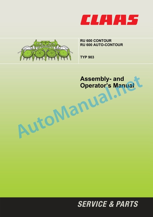
Claas Ru-600 Contour (903) Forage Harvesters Operator Manual EN
$50.00
- Model: Ru-600 Contour (903) Forage Harvesters
- Type Of Manual: Operator Manual
- Language: EN
- Format: PDF(s)
- Size: 14.7 MB
File List:
00 0293 623 0.pdf
00 0301 051 0.pdf
00 0303 482 0.pdf
00 0293 623 0.pdf:
1 Machine overview
2 Introduction
Introduction
Validity
3 Table of contents
4 Preface
Special care
Identification plate
Transport on public roads
Protective equipment for road transport
Driving lights during road transport
Ballasting
5 Safety rules
Identification of warning and danger signs
Intended use
General Safety and Accident Prevention Instructions
Safety decals with pictorials
Safety prop
6 Specifications
RU 600 Contour
RU 600 Auto-Contour
7 Prior to operation
Loading and unloading the maize header
Mounting the maize header for the first time
Adjustments to the forager
Additional weights
Required additional weights
Order numbers – additional weights
Additional lighting for road transport
Setting the drop rate
Mounting the safety covers
Assembly of maize header
Mount locking mechanism rod
Mount drive for intake auger (for delivery to USA)
Installing the universal drive shaft
Installing down-crop augers
Assembly of crop dividers/divider points
Installing crop dividers
Installing divider points
Adjusting crop dividers
Attaching push bar
Removing protective strip
Removing transport frame
Check and observe the following before putting into operation
Mounting the maize header
To mount the maize header, proceed as follows:
Unlocking
Attaching the maize header
Adjusting the lock mechanism
Adjusting the locking rods
Connecting the hydraulics
Connecting the power supply
Connecting universal drive shaft on forager
Adjusting dog clutch
Pivoting frame
Unlocking the swing stop
Locking the swing stop
Prop stands
Work and transport position
Transport position
Working position
Unhitching/setting down the maize header
8 Operation
Raising and lowering the maize header
Raise and lower side arms of the maize header
Using the maize header
Crop dividers
Adjusting the angle of the crop dividers
Adjusting the outer dividers
Adjusting the push bar
Adjusting the chopping length
Chopping length range
Adjusting the serrated strips
Adjusting the knives
Adjusting the hitch
Harvesting down-crop
OPTIONAL EQUIPMENT
Down-crop cones (D03 0070)
Deflector bar height increase (D03 0060)
CLAAS Autopilot (R03 0110)
Adjusting the sensors:
CLAAS Auto-Contour (R03 0070)
9 Maintenance
Important Maintenance Instructions
Spare parts
Hydraulic system
Lubrication
Gearboxes
Spur wheel gear (A)
Angle drive (B)
Main drive (C)
Bevel gear (D)
Angle drive (E)
Rotor drive (F)
Clearing gear (G)
Drives (H, I) for down-crop augers
Clutches
Lubricating the drive chain
Tensioning the drive chain
Replacing knives
Changing the knives:
Spring adjustment
Folding frame spring tension
Spring tension of intake auger
Hydraulic system
Hydraulic hose connections
Fixing elements
Bolted connections
Connecting elements
End of season storage
Lubricants chart
10 Lubrication chart
Safety rules
Lubricants
Lubrication
00 0301 051 0.pdf:
PROFI CAM 3
Table of contents
1 Introduction
1.1 Notes on the manual
1.1.1 Validity of manual
1.1.2 Information about this Operator’s Manual
1.1.3 Symbols and notes
1.1.4 Optional equipment
1.1.5 Qualified specialist workshop
1.1.6 Maintenance information
1.1.7 Warranty notes
1.1.8 Spare parts and technical questions
1.2 Intended use
1.2.1 Intended use
1.2.2 Reasonably foreseeable misuse
2 Safety
2.1 Identifying warnings
2.1.1 Hazard signs
2.1.2 Signal word
2.2 Safety rules
2.2.1 Meaning of Operator’s Manual
2.2.2 Observing safety decals and warnings
2.2.3 Optional equipment and spare parts
3 Product description
3.1 Overview and method of operation
3.1.1 How the PROFI CAM works
3.2 Identification plates and identification number
3.2.1 Position of identification plates
3.2.2 Explanation of PROFI CAM identification plate
3.3 Information on the product
3.3.1 CE marking
4 Operating and control elements
4.1 Camera system
4.1.1 Camera system monitor
4.2 Menu structure
4.2.1 Main menu
4.2.2
4.2.3
4.2.4
4.2.5
4.2.6
5 Technical specifications
5.1 PROFI CAM
5.1.1 Monitor
5.1.2 Camera
5.1.3 Switch box
5.1.4 Degree of protection against foreign bodies and water
6 Preparing the product
6.1 Shutting down and securing the machine
6.1.1 Switching off and securing the machine
6.2 Prior to operation
6.2.1 Carry out prior to operation
6.2.2 Installing the sun protection
6.2.3 Aligning the camera
6.2.4 Connecting the camera electrics
7 Operation
7.1 Monitor
7.1.1 Switching on the monitor
7.1.2 Calling up the menu
7.1.3 Setting a menu item
7.1.4 Setting the image orientation
7.1.5 Setting automatic screen darkening
7.1.6 Image mirroring
7.1.7 Setting the trigger view
7.1.8 Setting the follow-up time for trigger view
7.1.9 Setting the display mode
7.1.10 Activating/deactivating a display mode
8 Faults and remedies
8.1 Electrical and electronic system
8.1.1 Overview of problems on PROFI CAM camera system
8.1.2 Replacing the switch box fuse
9 Maintenance
9.1 Maintenance intervals
9.1.1 Every 10 operating hours or daily
9.2 Camera system
9.2.1 Checking the camera system for dirt
9.2.2 Cleaning the camera
9.2.3 Cleaning the switch box
9.2.4 Cleaning the monitor
10 Placing out of operation and disposal
10.1 General Information
10.1.1 Putting out of operation and disposal
11 Technical terms and abbreviations
11.1 Abbreviations
11.1.1 Units
11.1.2 Abbreviations
11.1.3 Technical terms
00 0303 482 0.pdf:
PROFI CAM 4
Table of contents
1 Introduction
1.1 Notes on the manual
1.1.1 Validity of manual
1.1.2 Information about this Operator’s Manual
1.1.3 Symbols and notes
1.1.4 Optional equipment
1.1.5 Qualified specialist workshop
1.1.6 Maintenance information
1.1.7 Notes on warranty
1.1.8 Spare parts and technical questions
1.2 Intended use
1.2.1 Intended use
1.2.2 Reasonably foreseeable misuse
2 Safety
2.1 Identifying warnings
2.1.1 Hazard signs
2.1.2 Signal word
2.2 Safety rules
2.2.1 Meaning of Operator’s Manual
2.2.2 Structural changes
2.2.3 Optional equipment and spare parts
2.2.4 Operation only following proper putting into operation
2.2.5 Technical status
2.2.6 Respecting technical limit values
Respecting technical limit values
2.2.7 Hazards when driving on roads and fields
3 Product description
3.1 Overview and method of operation
3.1.1 How the PROFI CAM works
3.2 Identification plates and identification number
3.2.1 Identification plates
3.3 Information on the product
3.3.1 CE marking
4 Operating and display elements
4.1 Camera system
4.1.1 Camera system monitor
4.1.2 CEBIS
4.2 Menu structure
4.2.1 Main menu
4.2.2
4.2.3
4.2.4
4.2.5
4.2.6
5 Technical specifications
5.1 PROFI CAM
5.1.1 Monitor
5.1.2 Camera
5.1.3 Switch box
6 Preparing the product
6.1 Switching off and securing the machine
6.1.1 Switching off and securing the machine
6.2 Prior to putting into operation
6.2.1 Carry out prior to operation
6.2.2 Installing the sun protection
6.2.3 Aligning the camera
7 Operation
7.1 Monitor
7.1.1 Switching on the monitor
7.1.2 Calling up the menu
7.1.3 Setting a menu item
7.1.4 Setting the image orientation
7.1.5 Setting automatic screen darkening
7.1.6 Image mirroring
7.1.7 Setting the trigger view
7.1.8 Setting the follow-up time for trigger view
7.1.9 Setting the display mode
7.1.10 Activating/deactivating a display mode
8 Faults and remedies
8.1 Electric and electronic system
8.1.1 Overview of problems on PROFI CAM camera system
9 Maintenance
9.1 Maintenance intervals
9.1.1 Every 10 operating hours or daily
9.2 Camera system
9.2.1 Checking the camera system for dirt
9.2.2 Cleaning the camera
9.2.3 Cleaning the switch box
9.2.4 Cleaning the monitor
10 Putting out of operation and disposal
10.1 General information
10.1.1 Putting out of operation and disposal
11 Technical terms and abbreviations
11.1 Abbreviations
11.1.1 Units
11.1.2 Abbreviations
11.1.3 Technical terms
John Deere Repair Technical Manual PDF
John Deere Repair Technical Manual PDF
John Deere Diesel Engines POWERTECH 2.9 L Component Technical Manual CTM126 Spanish
John Deere Repair Technical Manual PDF
John Deere DF Series 150 and 250 Transmissions (ANALOG) Component Technical Manual CTM147 05JUN98
John Deere Repair Technical Manual PDF
John Deere Application List Component Technical Manual CTM106819 24AUG20
John Deere Repair Technical Manual PDF
John Deere Repair Technical Manual PDF
John Deere Repair Technical Manual PDF
John Deere 18-Speed PST Repair Manual Component Technical Manual CTM168 10DEC07
John Deere Parts Catalog PDF
John Deere Tractors 7500 Parts Catalog CPCQ26568 30 Jan 02 Portuguese


