Claas Scorpion 741 (K33) Telehandlers Operator Manual ES
$50.00
- Model: Scorpion 741 (K33) Telehandlers
- Type Of Manual: Operator Manual
- Language: ES
- Format: PDF(s)
- Size: 284 MB
File List:
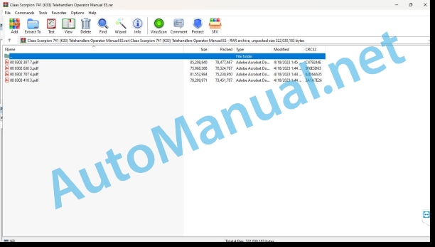
00 0302 307 7.pdf
00 0302 630 3.pdf
00 0302 707 4.pdf
00 0303 418 3.pdf
00 0302 307 7.pdf:
SCORPION 1033 VARIPOWERSCORPION 741 VARIPOWERSCORPION 736 VARIPOWERSCORPION 732 VARIPOWERSCORPION 635 VARIPOWER
1. Introduction
1.1 General information
1.1.1 Validity of the manual
1.1.2 Information about this instruction manual
1.1.3 Symbols and indications
1.1.4 Optional equipment
1.1.5 Qualified specialized workshop
1.1.6 Maintenance instructions
1.1.7 Information regarding warranty
1.1.8 Spare parts and technical questions
1.2 Proper application of the machine
1.2.1 Proper machine application
1.2.2 Intended knowing misuse
2 Security
2.1 Recognize warning signs
2.1.1 Danger symbols
2.1.2 Keyword
2.2 Safety instructions
2.2.1 Meaning of the instruction manual
2.2.2 Observe graphic danger symbols and alarm indications
2.2.3 Requirements for all people working with the machine
2.2.4 Children in danger
2.2.5 Danger zones
2.2.6 Accompanying persons
2.2.7 Coupling of machine and work equipment
2.2.8 Coupling the machine and trailer
2.2.9 Construction modifications
2.2.10 Optional equipment and spare parts
2.2.11 Protection against overturning and gravel impacts
2.2.12 Control of the machine in operation
2.2.13 Use only after correct commissioning
2.2.14 Technical status
2.2.15 Danger due to machine breakdowns
2.2.16 Comply with technical limit values
2.2.17 Maintain functional protection devices
2.2.18 Personal protective equipment
2.2.19 Wear appropriate clothing
2.2.20 Remove dirt and loose objects
2.2.21 Field of vision and vision aids
2.2.22 Prepare the machine for road traffic
2.2.23 Dangers when driving on the road and in the countryside
2.2.24 Tow the machine or pick it up with a crane
2.2.25 Lifted loads
2.2.26 Floor with load capacity
2.2.27 Park the machine safely
2.2.28 Unsuitable consumables
2.2.29 Safe handling of consumables and auxiliary materials
2.2.30 Fuel is harmful to health
2.2.31 Cooling agents are harmful to health
2.2.32 Environmental protection and waste disposal
2.2.33 Keep the cabin free of chemicals
2.2.34 Fire prevention
2.2.35 Deadly current discharge due to overhead power lines
2.2.36 Behavior in the case of voltage discharge through unprotected cables and lightning strikes
2.2.37 Electrical shock from electrical equipment
2.2.38 Vibrations can cause health injuries
2.2.39 Liquids under pressure
2.2.40 Toxic exhaust gases
2.2.41 Hot surfaces
2.2.42 Getting on and off safely
2.2.43 Work only on the stopped machine
2.2.44 Maintenance work and repair work
2.2.45 Danger from welding work
2.2.46 Check and charge the battery
2.3 Safety signage
2.3.1 Structure of graphic hazard symbols
2.3.2 Summary of graphic danger symbols
SCORPION 1033
SCORPION 741 / 736 / 732 / 635
2.3.3 Graphic danger symbols on the machine
Graphic danger symbol
Graphic danger symbol
Graphic danger symbol
Graphic danger symbol
Graphic danger symbol
Graphic hazard symbol
Graphic danger symbol
Graphic danger symbol
Graphic danger symbol
Graphic danger symbol
3 Machine Description
3.1 Summary and operation
3.1.1 Telehandler Overview
SCORPION 1033
SCORPION 741 / 736 / 732 / 635
3.2 Identification plates and identification numbers
3.2.1 Telescopic loader identification plate
3.2.2 CE approval
3.2.3 Cab identification plate
3.3 Machine information
3.3.1 Position of the stickers
SCORPION 1033
SCORPION 741 / 736 / 732 / 635
3.3.2 Adhesives
tie point
Stop point, lifting point
lifting point
Shift position*
Coolant liquid
Window washer fluid
Acoustic power level
Emergency exit
urea solution
Hydraulic oil
refueling nozzle
wheel nuts
Greasing scheme
Preheating device 230 V*
Tire pressure table
Brake fluid
Load capacity diagram
Joystick
Inching device and hand throttle*
Rear hydraulic installation*
Work focuses*
Maximum support load*
Manual lubrication points*
High Flow*
Front socket box*
Preheating device 120 V*
Maximum load capacity*
Cooling agent*
4 Control and display instruments
4.1 Cabin and driving position
4.1.1 Operator’s position
4.1.2 Control elements at the front
4.1.3 Control elements on the side console
4.1.4 Control elements on the right roof console
4.1.5 Control elements in the left roof console
4.1.6 Control elements for heating and air conditioning installation
4.1.7 Joystick
4.1.8 Steering control bar
4.1.9 Ignition contact
4.1.10 Indicator unit on the steering column
4.1.11 Load torque indicator
4.1.12 Level indicator
4.1.13 Pneumatic brake equipment pressure gauge*
4.1.14 Radio
4.1.15 Armrest
4.1.16 Control elements on the telescopic arm
4.2 On-board information system
4.2.1 Warning messages and fault messages
4.2.2 Display unit 3.5”
4.2.3 Display unit 7’’*
4.2.4 Status symbols on the display unit
5 Technical data
5.1 SCORPION
5.1.1 SCORPION 1033 Measurements
5.1.2 Measurements SCORPION 741
5.1.3 SCORPION 736 Measurements
5.1.4 Measurements SCORPION 732
5.1.5 Measurements SCORPION 635
5.1.6 Weight
5.1.7 Load capacity
5.1.8 Explanations regarding the load capacity diagram
Symbols on load capacity diagrams
5.1.9 SCORPION 1033 load capacity diagram
5.1.10 SCORPION capacity diagram
5.1.11 SCORPION 736 load capacity diagram
5.1.12 SCORPION 732 load capacity diagram
5.1.13 SCORPION 635 load capacity diagram
5.1.14 Static and dynamic checks
5.1.15 Support loads
Ground pressure calculation
Example of calculation on front tires on firm ground
Example of calculation on front tires on non-firm ground
Example of calculation on rear tires on firm ground
Example of calculation on rear tires on non-firm ground
Support surface on firm ground
Support surface in hollow floor
Support surface with bottom construction
Calculation example for front tires with lower construction
5.1.16 Vibrations
Vibrations in the hand and arm
Whole body vibrations
5.1.17 Sound pressure level and sound power level
5.1.18 Use temperature
5.1.19 TCD 3.6 L4 diesel engine
5.1.20 TCD 3.6 L4 diesel engine (D914)
5.1.21 Diesel engine CO2 emissions
5.1.22 Chassis
Propulsion
walking speed
5.1.23 Axes
front axle
Rear axle
5.1.24 Work equipment
5.1.25 Tires and tire pressure
5.1.26 Snow chains* or tire protection chains*
5.1.27 Foam filling in tires*
5.1.28 Brake
5.1.29 Address
5.1.30 Telescopic arm
5.1.31 Trailer hitch
Permit as an agricultural or forestry shooting machine
Permit as a self-propelled work machine
5.1.32 Electrical installation
5.1.33 Hydraulic installation
Working hydraulic system
5.1.34 Limitations of the SCORPION 1033 field of view
Limitation of field of vision with attached load
Limitation of field of view with load
Limiting the field of vision for loading a truck
5.1.35 Field of view limitations SCORPION 741 / 736 / 732
Limitation of field of vision with attached load
Limitation of field of view with load
Limiting the field of vision for loading a truck
5.1.36 Limitations of the SCORPION 635 field of view
Limitation of field of vision with attached load
Limitation of field of view with load
Limiting the field of vision for loading a truck
5.1.37 Stability during work
Requirements for lifting work
Requirements for transportation work
5.1.38 Stability during work with lifting eye*
Requirements for lifting work
Requirements for transportation work
5.2 Inputs
5.2.1 Lubricants
5.2.2 Hydraulic oil
5.2.3 Brake fluid
5.2.4 Coolant liquid
5.2.5 Fuels
5.2.6 Cooling agent
5.2.7 Window washer fluid
6 Preparation of the machine
6.1 Turn off the machine and secure it
6.1.1 Turn off the machine and secure it
6.1.2 Lowering work equipment onto the ground
6.1.3 Connect the battery separator switch
6.1.4 Secure the machine so that it cannot roll
6.1.5 Unfolding and folding the folding chocks*
6.1.6 Stopping the propulsion with the emergency stop switch
6.1.7 Activate the parking position
6.2 Access jobs and maintenance positions
6.2.1 Access and leave the operator’s cabin
Ascend and descend
Access the operator’s cabin
Leaving the operator’s cabin
6.3 Diesel engine
6.3.1 Select a permitted fuel
6.3.2 Take into account the fuel specification
6.3.3 Take into account the urea specification
Use of urea solution
Purity and regulations of urea solution
Storage of urea solution in tanks and containers
Properties of urea solution at high and low outside temperatures
6.3.4 Use winter fuel at low temperatures
6.3.5 Refuel the machine
Refuel urea solution
6.4 Work equipment
6.4.1 Dismantle work equipment
6.4.2 Release the pressure in the hydraulic system
Release hydraulic pressure in control circuit III
Pressure relief* from control circuit III / control circuit III High Flow*
Release hydraulic pressure in control circuit IV*
6.4.3 Separate the hydraulic pipes from the control circuit III
Separate the connections of the control circuit III
Separate the connections of the transmission III control circuit*
Separate the leak oil connection*
6.4.4 Separate the hydraulic pipes from the III High Flow* control circuit
6.4.5 Separate multiple coupling*
6.4.6 Separate the front socket*
6.4.7 Dismantling the working equipment from the mechanical tool holder*
6.4.8 Dismantling the work equipment from the hydraulic tool holder*
6.4.9 Assemble work equipment
6.4.10 Mount the work equipment on the mechanical tool holder*
6.4.11 Mount the work equipment on the hydraulic tool holder*
6.4.12 Join the hydraulic pipes of the control circuit III
Orient the hydraulic pipe connections
Join the connections of the control circuit III
Join the connections of the transmission III control circuit*
Join the leak oil connection*
6.4.13 Join the hydraulic pipes of the III High Flow* control circuit
6.4.14 Join the multiple coupling*
6.4.15 Connect the front socket*
6.4.16 Carry out a check on the jamming of work equipment
Visual control
Mechanical control
6.4.17 Join the hydraulic pipes of the control circuit IV*
Join the connections of the IV control circuit
6.4.18 Separate the hydraulic pipes from the control circuit IV*
6.4.19 Connect the rear socket*
6.5 Towing device
6.5.1 Connecting the trailer with tipping function*
6.5.2 Separating the trailer with tipping function*
6.6 Load the machine
6.6.1 Prepare the machine for loading
6.6.2 Load the machine
6.6.3 Tie the machine
6.6.4 Driving the machine to a loading surface
6.6.5 Removing the machine from a loading surface
7 Management
7.1 Driving and transportation
7.1.1 Prepare for driving
7.1.2 Prepare for road traffic
7.1.3 Perform a functional check
7.1.4 Driving
Start the machine
7.1.5 Place the work equipment in transport position
7.1.6 Pick up and unload the material
7.1.7 Flatten
Flatten moving forward
Flatten reverse
7.1.8 Loading a transport vehicle
7.1.9 Pick up the load from the ground
7.1.10 Pick up load deposited on high
7.1.11 Support the load on the ground
7.1.12 Deposit load high
7.1.13 Towing the machine from the danger zone
Towing points and tow truck pick-up points
Prepare the machine for towing
Tow the machine
After the towing process
7.1.14 Load games counter*
Count loading game
Reset load game counter
7.2 Diesel engine
7.2.1 Connect the diesel engine
Synchronize address
Bring the hydraulic oil to operating temperature
7.2.2 Turn off the diesel engine
7.2.3 Preheating device for hydraulic oil and coolant (230 V / 120 V)*
Activate preheating
Deactivate preheating
7.2.4 Fuel preheating device (12 V)*
7.3 Chassis
7.3.1 Select the feed direction
7.3.2 Select gear range
7.3.3 Inching device*
7.3.4 Unevenness compensation*
7.3.5 Vibration damping*
7.3.6 Hand throttle*
7.3.7 Open and close the high pressure valves of the propulsion pump
7.4 Brake
7.4.1 Brake the machine
7.4.2 Engaging and disengaging the parking brake
7.4.3 Release and mechanically close the parking brake
Release the parking brake
Close the parking brake
7.5 Address
7.5.1 Setting the address type
Adjust front steering
Adjust steering to all four wheels
Adjust the crab pitch
Adjust manual crab pitch without lock key
Adjust the manual crab pitch with the lock key
Correct rear axle steering angle
7.6 Work equipment
7.6.1 Prepare work with work equipment
7.6.2 Lock and release the working hydraulic system
7.6.3 Load torque indicator function
7.6.4 Check the load torque indicator
7.6.5 Raise and lower the telescopic arm
Raise the telescopic arm
Lower the telescopic arm
7.6.6 Removing and inserting the telescopic projection
Remove the telescopic projection
Insert the telescopic projection
7.6.7 Pick up or dump work equipment
Pick up work equipment
Dump work equipment
7.6.8 Automatic bucket pick-up*
7.6.9 Control circuit III
Manage the control circuit III
Adjust flow rate*
Change control circuit III*
7.6.10 Control circuit III High Flow*
Operate the III High Flow control circuit
Adjust flow rate*
7.6.11 Control circuit IV*
Manage the IV control circuit
Adjust flow rate*
7.6.12 Tilting cylinder lock*
7.6.13 Emergency descent*
Activate emergency descent
7.7 Towing device
7.7.1 Summary of coupling jaws
7.7.2 Operate the automatic coupler
Adjust the height of the hitch mouth
hitch a trailer
Uncouple the trailer
7.7.3 Handle the Piton hitch
Adjust the height of the hitch mouth
hitch a trailer
Uncouple the trailer
7.7.4 Handle the ball hitch
Adjust the height of the hitch mouth
Adjust the height of the pusher
hitch a trailer
Uncouple the trailer
7.7.5 Handle the Cradle hitch
Adjust the height of the hitch mouth
hitch a trailer
Uncouple the trailer
7.7.6 Operate the maneuvering device
hitch a trailer
Uncouple the trailer
7.7.7 Handle automatic bolt coupling
hitch a trailer
Uncouple the trailer
7.7.8 Handle bolt coupling
hitch a trailer
Uncouple the trailer
7.7.9 Handle the hook hitch
Adjust the hitch mouth
hitch a trailer
Uncouple the trailer
Adjust the hitch mouth
hitch a trailer
Uncouple the trailer
7.7.10 Connect the pneumatic brake equipment*
7.7.11 Operate pneumatic brake equipment*
7.7.12 Connect and disconnect the antifreeze pump for the pneumatic brake system*
7.7.13 Connect the hydraulic trailer brake*
1-duct system*
Connect the brake pipe
Remove the brake pipe
2-duct system*
Connect the brake pipe
Remove the brake pipe
7.7.14 Operate the trailer hydraulic brake*
7.7.15 Driving the trailer with tipping function
Raise and lower the dump truck
Raise and lower the dump truck
7.8 Electrical and electronic system
7.8.1 Electronic feed lock*
Program the ignition key
Delete ignition key
7.8.2 Camera system*
Adjust the side camera*
Correct the angle
Adjust the rear camera*
Correct the angle
7.8.3 Reversing device
Reversing horn
7.8.4 Adjust the rotating flashing light*
Turning the rotating flashing light on and off
Remove rotating flashing light
Fold the omnidirectional light*
7.8.5 Switching the limit light on and off
7.9 Cabin and driving position
7.9.1 Open the emergency exit
7.9.2 Adjust the operator’s seat
7.9.3 Putting on the seat belt
7.9.4 Adjust the steering column
Adjust the distance of the steering wheel
Adjust the height of the steering wheel
Adjust steering wheel tilt
7.9.5 Adjust heating, ventilation and air conditioning installation*
Adjust the temperature
Adjust the fan
Connect and disconnect the air conditioning installation*
7.9.6 Open and close the cabin windows
Open the top of the cabin door a crack
Open the top of the cabin door by 180°
Open the rear cabin window
7.9.7 Adjust the sun visor*
7.9.8 Turning the cabin interior lighting on and off
7.9.9 Adjust visual aids
Adjust the interior mirror
Adjust the rearview mirror and right side mirror
Adjust the rearview mirror and left side mirror
Adjust the front visual aid*
Adjust rear view assist*
7.9.10 Activate the window washer unit
Activate the front windshield washer unit
Activate the rear windshield washer unit
7.9.11 Remove the front protective grille*
7.10 Centralized lubrication
7.10.1 Central lubrication system*
8 Incident and solution
8.1 Overview
8.1.1 Reset the maintenance indicator
8.1.2 Summary of error codes
8.1.3 Summary of error codes
8.2 Diesel engine 82.1 Summary of diesel engine faults
8.2.2 Summary of malfunctions in air filter equipment
8.2.3 Summary of incidents in the exhaust aftertreatment system
Warning and malfunction strategies
Urea tank symbols
Exhaust gas aftertreatment system symbols
Diesel particulate filter symbols*
Bypass derating
8.3 Brake
8.3.1 Summary of incidents in brake equipment
8.4 Address
8.4.1 Summary of incidents in the management team
8.5 Work equipment
8.5.1 Summary of incidents in work equipment
8.6 Hydraulic installation
8.6.1 Summary of incidents in the hydraulic installation
8.7 Electrical and electronic system
8.7.1 External boot process
Connect the external battery
Disconnect the external battery
8.7.2 Summary of incidents in the electrical installation
8.7.3 Summary of malfunctions in the electronic starter lock*
8.7.4 Fuses in the engine compartment
8.7.5 Fuses in the cabin
8.7.6 Relay in engine space
8.7.7 Relays in the cabin
8.7.8 Prepare welding jobs
8.8 Cabin and driving position
8.8.1 Summary of heating incidents
Heating performance
Coolant performance
8.9 Centralized lubrication
8.9.1 Summary of faults in the central lubrication system*
9 Maintenance
9.1 Prepare maintenance
9.1.1 Place the machine in maintenance position
9.1.2 Place the safety support*
9.1.3 Open and close the engine hood
9.2 Maintenance intervals
9.2.1 Every 10 hours of service or daily
9.2.2 Every 50 hours of service
9.2.3 After the first 100 hours of service
9.2.4 Every 250 hours of service
9.2.5 After the first 500 hours of service
9.2.6 Every 500 hours of service
9.2.7 Every 1000 hours of service
9.2.8 Every 1500 hours of service
9.2.9 Every 2 years
9.2.10 Every 2000 hours of service
9.2.11 Every 3000 hours of service
9.2.12 Every 4000 hours of service
9.2.13 Every 6000 hours of service
9.2.14 Every 10,000 hours of service
9.3 Greasing scheme
9.3.1 Grease the lubrication points every 50 hours of service
Central grease points*
Hitch hook* and lifting eye*
9.3.2 Grease the lubrication points every 250 hours of service
9.4 Diesel engine
9.4.1 Clean the diesel engine
9.4.2 Difficulty factors for
9.4.3 Check the diesel engine oil level (TCD 3.6 L4 / TCD 3.6 L4 (D914))
Check the oil level
Fill oil
9.4.4 Drain condensation water from the fuel prefilter (TCD 3.6 L4)
9.4.5 Drain condensation water from the fuel prefilter (TCD 3.6 L4 (D914))
9.4.6 Empty condensation water and bottom deposits from the fuel tank
9.4.7 Bleeding the fuel system (TCD 3.6 L4 / TCD 3.6 L4 (D914))
9.4.8 Clean the cooling system (TCD 3.6 L4 / TCD 3.6 L4 (D914))
9.4.9 Adjust the reversible fan*
9.4.10 Check the coolant level (TCD 3.6 L4 / TCD 3.6 L4 (D914))
Check the filling level
Fill coolant
9.4.11 Clean or change the air filter elements (TCD 3.6 L4 (D914))
Remove the filter element
Clean the filter housing and cover
Change the security element
Install the filter element
9.4.12 Clean or change the air filter elements (TCD 4.1 L4 / TCD 3.6 L4)
Remove the filter element
Clean the filter element
Clean the filter housing and cover
Change the security element
Install the filter element
9.4.13 Clean the dust evacuation valve of the air filter (TCD 3.6 L4 (D914))
Clean the dust evacuation valve
Check dust evacuation*
9.4.14 Clean the dust evacuation valve of the air filter (TCD 4.1 L4 / TCD 3.6 L4)
Clean the lid
Clean the dust evacuation valve
9.4.15 Regenerate the exhaust aftertreatment system
Automatic regeneration
Manually start regeneration
Cancel regeneration
Regenerate the diesel particulate filter*
9.5 Chassis
9.5.1 Check wheels, tires and tire pressure
9.5.2 Check tire air pressure
9.5.3 Check the tightening torque of the wheel nuts
9.6 Brake
9.6.1 Check the operation and effect of the service brake
9.6.2 Check the operation and effect of the parking brake
9.6.3 Check the brake fluid level of the service brake
Refill brake fluid
9.6.4 Empty the pneumatic brake compressed air tank of water*
9.7 Address
9.7.1 Check steering operation
9.8 Telescopic arm
9.8.1 Grease the sliding surfaces on the telescopic projection
9.8.2 Lubricate the rear sliding elements
9.8.3 Check the front sliding elements
9.8.4 Preserve piston rods
9.9 Hydraulic installation
9.9.1 Check the hydraulic oil level
Check the filling level
Fill hydraulic oil
9.9.2 Check the hydraulic hoses
Marking of hydraulic hoses
9.10 Electrical and electronic system
9.10.1 Control lighting
9.10.2 Check the operation of the load torque limitation
Prepare the machine
Check load torque limitation with standard fork
Check load torque limitation with special fork
9.11 Cabin and driving position
9.11.1 Check the condition and operation of the seat belt
9.11.2 Clean or change the cabin air prefilter*
9.11.3 Check the fill level of the windshield wiper equipment
9.12 Centralized lubrication
9.12.1 Check the fill level of the central lubrication system*
Check the filling level
Fill lubricant
9.13 Assembled parts and machine casing
9.13.1 Clean the machine
Before cleaning
Cleaning
After cleaning
9.13.2 Check the fire extinguisher
10 Decommissioning and waste disposal
10.1 General information
10.1.1 Decommissioning and waste disposal
11 EC declaration of conformity
11.1 SCORPION
11.1.1 EC declaration of conformity (model)
00 0302 630 3.pdf:
1. Introduction
1.1 General information
1.1.1 Validity of the manual
1.1.2 Information about this instruction manual
1.1.3 Symbols and indications
1.1.4 Optional equipment
1.1.5 Qualified specialized workshop
1.1.6 Maintenance instructions
1.1.7 Information regarding warranty
1.1.8 Spare parts and technical questions
1.2 Proper application of the machine
1.2.1 Proper machine application
1.2.2 Intended knowing misuse
2 Security
2.1 Recognize warning signs
2.1.1 Danger symbols
2.1.2 Keyword
2.2 Safety instructions
2.2.1 Meaning of the instruction manual
2.2.2 Observe graphic danger symbols and alarm indications
2.2.3 Requirements for all people working with the machine
2.2.4 Children in danger
2.2.5 Danger zones
2.2.6 Accompanying persons
2.2.7 Coupling of machine and work equipment
2.2.8 Coupling the machine and trailer
2.2.9 Construction modifications
2.2.10 Optional equipment and spare parts
2.2.11 Protection against overturning and gravel impacts
2.2.12 Control of the machine in operation
2.2.13 Use only after correct commissioning
2.2.14 Technical status
2.2.15 Danger due to machine breakdowns
2.2.16 Comply with technical limit values
2.2.17 Maintain functional protection devices
2.2.18 Personal protective equipment
2.2.19 Wear appropriate clothing
2.2.20 Remove dirt and loose objects
2.2.21 Field of vision and vision aids
2.2.22 Prepare the machine for road traffic
2.2.23 Dangers when driving on the road and in the countryside
2.2.24 Tow the machine or pick it up with a crane
2.2.25 Lifted loads
2.2.26 Floor with load capacity
2.2.27 Park the machine safely
2.2.28 Unsuitable consumables
2.2.29 Safe handling of consumables and auxiliary materials
2.2.30 Fuel is harmful to health
2.2.31 Cooling agents are harmful to health
2.2.32 Environmental protection and waste disposal
2.2.33 Keep the cabin free of chemicals
2.2.34 Fire prevention
2.2.35 Deadly current discharge due to overhead power lines
2.2.36 Behavior in the case of voltage discharge through unprotected cables and lightning strikes
2.2.37 Electrical shock from electrical equipment
2.2.38 Vibrations can cause health injuries
2.2.39 Liquids under pressure
2.2.40 Toxic exhaust gases
2.2.41 Hot surfaces
2.2.42 Getting on and off safely
2.2.43 Work only on the stopped machine
2.2.44 Maintenance work and repair work
2.2.45 Danger from welding work
2.2.46 Check and charge the battery
2.3 Safety signage
2.3.1 Structure of graphic hazard symbols
2.3.2 Summary of graphic danger symbols
SCORPION 1033
SCORPION 741 / 736 / 732 / 635
2.3.3 Graphic danger symbols on the machine
Graphic danger symbol
Graphic danger symbol
Graphic danger symbol
Graphic danger symbol
Graphic danger symbol
Graphic hazard symbol
Graphic danger symbol
Graphic danger symbol
Graphic danger symbol
Graphic danger symbol
3 Machine Description
3.1 Summary and operation
3.1.1 Telescopic loader summary
SCORPION 1033
SCORPION 741 / 736 / 732 / 635
3.2 Identification plates and identification numbers
3.2.1 Telescopic loader identification plate
3.2.2 Cab identification plate
3.3 Machine information
3.3.1 Position of the stickers
SCORPION 1033
SCORPION 741 / 736 / 732 / 635
3.3.2 Adhesives
tie point
Stop point, lifting point
lifting point
Coolant liquid
Window washer fluid
Acoustic power level
Emergency exit
Hydraulic oil
refueling nozzle
wheel nuts
Greasing scheme
Preheating device 230 V*
Tire pressure table
Brake fluid
Load capacity diagram
Joystick
Hand throttle*
Address Types
Work focuses*
Maximum support load*
Inching device*
Manual lubrication points*
Maximum load capacity*
Cooling agent*
4 Control and display instruments
4.1 Cabin and driving position
4.1.1 Operator’s position
4.1.2 Control elements at the front
4.1.3 Control elements on the side console
4.1.4 Control elements on the right roof console
4.1.5 Control elements in the left roof console
4.1.6 Control elements for heating and air conditioning installation
4.1.7 Joystick
4.1.8 Steering control bar
4.1.9 Ignition contact
4.1.10 Indicator unit on the steering column
4.1.11 Load torque indicator
4.1.12 Level indicator
4.1.13 Pneumatic brake equipment pressure gauge*
4.1.14 Radio
4.1.15 Armrest
4.1.16 Control elements on the telescopic arm
4.2 On-board information system
4.2.1 Warning messages and fault messages
4.2.2 Indicator unit
4.2.3 Screen
4.2.4 Menu
4.2.5
4.2.6 Menu
4.2.7
5 Technical data
5.1 SCORPION
5.1.1 SCORPION 1033 Measurements
5.1.2 Measurements SCORPION 741
5.1.3 SCORPION 736 Measurements
5.1.4 Measurements SCORPION 732
5.1.5 Measurements SCORPION 635
5.1.6 Weight
5.1.7 Load capacity
5.1.8 Explanations regarding the load capacity diagram
Symbols on load capacity diagrams
5.1.9 SCORPION 1033 load capacity diagram
5.1.10 SCORPION 741 load capacity diagram
5.1.11 SCORPION 736 load capacity diagram
5.1.12 SCORPION 732 load capacity diagram
5.1.13 SCORPION 635 load capacity diagram
5.1.14 Static and dynamic checks
5.1.15 Support loads
Ground pressure calculation
Example of calculation on front tires on firm ground
Example of calculation on front tires on non-firm ground
Example of calculation on rear tires on firm ground
Example of calculation on rear tires on non-firm ground
Support surface on firm ground
Support surface in hollow floor
Support surface with bottom construction
Calculation example for front tires with lower construction
5.1.16 Vibrations
Vibrations in the hand and arm
Whole body vibrations
5.1.17 Sound pressure level and sound power level
5.1.18 Use temperature
5.1.19 TCD 3.6 L4 diesel engine
5.1.20 Chassis
Propulsion
5.1.21 Axes
front axle
Rear axle
5.1.22 Work equipment
5.1.23 Tires and tire pressure
5.1.24 Snow chains* or tire protection chains*
5.1.25 Foam filling in tires*
5.1.26 Brake
5.1.27 Address
5.1.28 Telescopic arm
5.1.29 Trailer hitch
Permit as an agricultural or forestry shooting machine
Permit as a self-propelled work machine
5.1.30 Electrical installation
5.1.31 Hydraulic installation
Working hydraulic system
5.1.32 Limitations of the SCORPION 1033 field of view
Limitation of field of vision with attached load
Limitation of field of view with load
Limiting the field of vision for loading a truck
5.1.33 Field of view limitations SCORPION 741 / 736 / 732
Limitation of field of vision with attached load
Limitation of field of view with load
Limiting the field of vision for loading a truck
5.1.34 Limitations of the SCORPION 635 field of view
Limitation of field of vision with attached load
Limitation of field of view with load
Limiting the field of vision for loading a truck
5.1.35 Stability during work
Requirements for lifting work
Requirements for transportation work
5.1.36 Stability during work with lifting eye*
Requirements for lifting work
Requirements for transportation work
5.2 Inputs
5.2.1 Lubricants
5.2.2 Hydraulic oil
5.2.3 Brake fluid
5.2.4 Coolant liquid
5.2.5 Fuels
5.2.6 Cooling agent
5.2.7 Window washer fluid
6 Preparation of the machine
6.1 Turn off the machine and secure it
6.1.1 Turn off the machine and secure it
John Deere Repair Technical Manual PDF
John Deere Application List Component Technical Manual CTM106819 24AUG20
John Deere Repair Technical Manual PDF
John Deere Repair Technical Manual PDF
John Deere Repair Technical Manual PDF
John Deere Transmission Control Unit Component Technical Manual CTM157 15JUL05
John Deere Repair Technical Manual PDF
John Deere Diesel Engines PowerTech 4.5L and 6.8L – Motor Base Technical Manual 07MAY08 Portuguese
John Deere Repair Technical Manual PDF
John Deere Repair Technical Manual PDF
John Deere Repair Technical Manual PDF
John Deere 16, 18, 20 and 24HP Onan Engines Component Technical Manual CTM2 (19APR90)
John Deere Repair Technical Manual PDF

