Claas Sunspeed 16-70, 12-75 70, 8-75 70 (443) Combines Technical System EN
$150.00
- Model: Sunspeed 16-70, 12-75 70, 8-75 70 (443) Combines
- Type Of Manual: Technical System
- Language: EN
- Format: PDF(s)
- Size: 267 MB
File List:
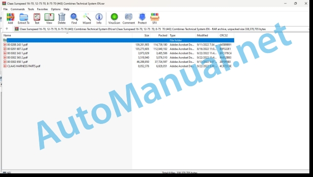
00 0288 243 1.pdf
00 0291 687 2.pdf
00 0302 343 1.pdf
00 0302 565 2.pdf
00 0302 658 1.pdf
CLAAS HARNESS PARTS.pdf
00 0302 343 1.pdf:
PROFI CAM 3
Table of contents
General information
Marking of warnings and hazard prevention notes
First-aid measures
CCN explanation
CCN (CLAAS Component Number)
Electric system standard
Overview
Hydraulic system standard
Overview
CCN (CLAAS Component Number)
10 Electrical / Electronic equipment
1030 Board computer / Indicators
Camera system
Description of function
1097 Testing / Measuring / Adjusting
Testing / measuring / adjusting the PROFI CAM
Checking the fuse in the video channel select box (C102)
Testing the video camera connector (C055)
1098 Fault / remedy
Fault / remedy PROFI CAM
The video monitor (C101) shows no image or cannot be switched on (indicator light fails to light up)
Video monitor (C102) displays a blue image either permanently or temporarily
The video monitor image is blurred
Replacing the fuse in the video channel select box (C102)
Connection and connecting cable with video camera (C055)
00 0302 565 2.pdf:
Sensor system
Table of contents
CCN explanation
CCN (CLAAS Component Number)
Electric system standard
Overview
Hydraulic system standard
Overview
CCN (CLAAS Component Number)
Introduction
Safety rules
Safety and hazard information
10 Electrical / Electronic equipment
1097 Testing / Measuring / Adjusting
Test report of the angle sensor (0011780.x)
Application of test report
Required tools
Test report of the angle sensor (0011780.x)
Testing / Measuring / Adjusting of angle sensor (0011780.x)
1. Reason for test
2. Mechanical test of angle sensor
3. Electric test with CDS
4. Electric test with multimeter
5. Mechanical test of connecting cable
Completing the machine
Test report of position and speed sensors
Application of test report
Required tools
Sensor variants
Part numbers of speed sensors
Part number of position sensor
Test report of position and speed sensors
Testing / measuring / adjusting of position and speed sensors
1. Reason for test
2. Mechanical test
3. Electric test with CDS
4a. Installation dimensions
Check of installation dimension
Installation dimensions of gearbox speed sensor (0011 799.x) and cam speed sensor (0011 810.x)
Installation dimension of position sensor (0011 815.x)
4b. Installation position
Centring of sensor
Metal-free zone
5. Electric test with multimeter
Voltage measurement
Direction of rotation and speed sensor (0011 605.x)
Measured values table
6. Mechanical test of connecting cable
Completing the machine
Test report of the urea sensor (00 0773 207 x)
Application of test report
Required tools
Parts number of the urea sensor
Test report of the urea sensor
Testing / measuring / adjusting urea sensor
1. Reason for test
2. Mechanical test
3. Mechanical test of connecting cable
4. Electric test with multimeter
5. Component test with the CDS
00 0302 658 1.pdf:
TUCANO 580 / 570 / 560 / 550TUCANO 450 / 440 / 430 / 420TUCANO 340 / 320TUCANO 580 / 570 / 560 MONTANATUCANO 450 / 430 MONTANA
Table of contents
Introduction
Safety rules
Safety and hazard information
Validity of manual
Validity of manual
CCN explanation
CCN (CLAAS Component Number)
Electric systems standard
Overview
Hydraulic system standard
Overview
CCN (CLAAS Component Number)
01 Engine
0150 Engine attachment parts
Starting the diesel engine, diesel engine speed adjustment – PERKINS
Measured values table
Description of function
Starting the diesel engine, diesel engine speed adjustment – Daimler (MTU)
Measured values table
Description of function
0155 Engine control
Diesel engine monitoring – PERKINS
Measured values table
Description of function
Diesel engine monitoring – Daimler (MTU)
Measured values table
Description of function
03 Chassis
0315 Drive axle
MONTANA differential lock
Measured values table
Description of function
0330 Driven steering axle, rear
4-Trac (NAF)
Measured values table
Description of function
Radial piston motor, NAF (fixed-displacement motor)
Description of function
Rear drive axle NAF hydraulic unit
Rear drive axle NAF assembly drawings
Key to diagram
Rear drive axle NAF wheel hub gearbox
Rear drive axle NAF valve block
Description of function
4-TRAC (MUD HOG)
Measured values table
Description of function
Radial piston motor, MUD HOG (fixed-displacement motor)
Key to diagram
Description of function
Radial piston motor, MUD HOG (fixed-displacement motor)
Valve unit, MUD HOG
Key to diagram
Description of function
0335 Ground drive
Hydrostatic ground drive – PERKINS with brake restrictor valve
Description of function
Pump unit (HPV)
Description of function
Servo-control valve
Description of function
Multifunction valve (7013/7014)
Description of function
Ground drive fixed-displacement motor (HMF)
Description of function
Hydrostatic ground drive – PERKINS without brake restrictor valve
Description of function
Pump unit (HPV)
Description of function
Servo-control valve
Description of function
Multifunction valve (7013/7014)
Description of function
Ground drive fixed-displacement motor (HMF)
Description of function
Hydrostatic ground drive – MTU with brake restrictor valve
Description of function
Pump unit (HPV)
Description of function
Servo-control valve
Description of function
Multifunction valve (7013/7014)
Description of function
Ground drive fixed-displacement motor (HMF)
Description of function
Hydrostatic ground drive – MTU without brake restrictor valve
Description of function
Pump unit (HPV)
Description of function
Servo-control valve
Description of function
Multifunction valve (7013/7014)
Description of function
Ground drive fixed-displacement motor (HMF)
Description of function
Hydrostatic ground drive – MONTANA
Description of function
Pump unit (HPV)
Description of function
Servo-control valve
Description of function
Multifunction valve (7013/7014)
Description of function
0370 Slope regulation
Slope control (MONTANA)
Measured values table
Description of function
04 Brake
0405 Service brake
Service brake – power-operated
Measured values table
Description of function
05 Steering
0505 Steering
Steering system
Neutral function diagram
Steering-actuated function diagram
Checking the steering system
Description of function
0510 Automatic steering
Autopilot / Sensing system
Measured values table
Description of function
Checking the Autopilot system
Autopilot / LASER PILOT
Measured values table
Description of function
Checking the Autopilot system
GPS Steering system – Basic machine with S7 / S10 terminal
Measured values table
Description of function
GPS Steering system – EGNOS with S7 / S10 terminal
Description of function
GPS steering system – OMNISTAR HP with S7 / S10 terminal
Description of function
GPS steering system – RTK with S7 / S10 terminal
Description of function
GPS Pilot with RTK
GPS steering system – RTK NET with S7 / S10 terminal
Description of function
GPS steering system – BASELINE HD with S7 / S10 terminal
Description of function
09 Hydraulic system
0910 Pumps
Ground drive variable-displacement pump / gear pumps – applies to: with brake restrictor valve
Ground drive variable-displacement pump / gear pumps – applies to: without brake restrictor valve
Ground drive variable-displacement pump – applies to: MONTANA
Reel drive pump
0920 Valves
Main valve
Description of function
AUTO CONTOUR / reversing valve block
Front attachment dampening valve block
Threshing concave valve block
Storage block, threshing concave
Steering (Orbitrol) valve block
Autopilot GPS 1+ control valve block
AUTO PILOT GPS 1+ priority valve
Low-pressure hydraulics valve block
MONTANA master valve
MONTANA axle hydraulics valve block
Differential lock valve block
MONTANA brake system valve block
Valve block, four-wheel drive (4-TRAC)
MONTANA four-wheel drive valve block
Valve block, rotor variable-speed drive
Grain tank unloading tube valve block
Valve block, sample gate – yield meter
0925 Hydraulic Motors
Variable-displacement motor – applies to: MONTANA
0980 Hydraulic circuit diagram
Vehicle hydraulic system circuit diagrams
SCM 01a – Hydrostatic ground drive – applies to: with brake restrictor valve
SCM 01b – Hydrostatic ground drive – applies to: without brake restrictor valve
SCM 01c – Ground drive hydraulics circuit diagram – applies to: MONTANA
SCM 02a – Working hydraulics – applies to: Rotor machine
SCM 02b – Working hydraulics – applies to: straw walker machine with APS
SCM 02c – Working hydraulics – applies to: straw walker machine without APS
SCM 03a – Low-pressure hydraulics, reel drive circuit diagram – applies to: rotor machine
SCM 03b – Low-pressure hydraulic system circuit diagram, reel drive – applies to: straw walker machine
SCM 04 – Steering hydraulics – applies to: Autopilot
SCM 05 – Straw spreader
SCM 06a – Brake hydraulics circuit diagram
SCM 06b – Brake hydraulics circuit diagram – applies to: MONTANA
SCM 07 – MONTANA axle hydraulics circuit diagram
Front attachment hydraulics circuit diagrams
Cutterbar C370-C490 (type 527)
Cutterbar C500-C930 / V500-V930 (type 528) – SCM 01 – reel drive
Cutterbar C500-C930 / V500-V930 (type 528) – SCM 02 – rape cutter drive
Cutterbar C500-C930 / V500-V930 (type 528) – SCM 03 – cutting table adjustment
Cutterbar C500-C930 / V500-V930 (type 528) – SCM 04 – reel adjustment
VARIO cutterbar V540-V900 (type 716)
Rape cutter – Drive / VARIO cutterbar V540-V1050 (type 716)
Folding cutterbar 450-540 (type 713)
Conspeed 6-row
Conspeed 8-row
Sunspeed (type 443) hydraulic circuit diagram
10 Electrical / Electronic equipment
1010 Central electrics
Basic central terminal compartment
Label (basic central terminal compartment)
Fuse assignment
Relay assignment
Connector (basic central terminal compartment)
Connector designations
Roof central terminal compartment
Label (roof central terminal compartment)
Fuse assignment
Relay assignment
Connector designations
Patch field
Key to diagram
1012 Modules / sensors
Module A004 – DGPS modem (RTK)
Key to diagram
Key to diagram
Module A004 – DGPS modem (BASELINE HD)
Key to diagram
Key to diagram
Module A006 – Automatic air conditioner (ACM)
Key to diagram
Key to diagram
Module A007 – Cab fan (CFC)
Key to diagram
Key to diagram
Module A009 – Autopilot (ATP)
Key to diagram
Key to diagram
Module A015 – Electronic engine control (ECM) – Perkins TIER 3
Key to diagram
Key to diagram
Module A015 – electronic engine control (ECM) – Daimler (OM 906, OM 926 Tier 3)
Key to diagram
Key to diagram
Module A015 – electronic engine control (ECM) – Daimler (OM 936 TIER 5)
Key to diagram
Key to diagram
Module A017 – Engine adaptation (ADM) – Daimler (OM 906, OM 926 Tier 3)
Key to diagram
Key to diagram
Module A017 – engine adaptation (ADM) – Daimler (OM 936 TIER 5)
Key to diagram
Key to diagram
Module A021 – Yield meter module (YMM)
Key to diagram
Key to diagram
Module A025 – Sieve adjustment (SAM)
Key to diagram
Key to diagram
Module A026 – Deflector adjustment (DAM)
Key to diagram
Key to diagram
Module A027 – VARIO cutterbar (VAR)
Key to diagram
Key to diagram
Module A032 – reduction catalytic converter (SCR) – Daimler (OM 936 TIER 5)
Key to diagram
Key to diagram
Module A038 – Rotor (RTR)
Key to diagram
Key to diagram
Module A042 – MONTANA (MOM)
Key to diagram
Key to diagram
Module A065 – GPS PILOT terminal S7
Key to diagram
Key to diagram
Module A069 – vehicle base module (VBM)
Module A069 – Vehicle base module (VBM – 1/3) – Sensors part 1
Module A069 – Vehicle base module (VBM – 2/3) – Sensors part 2
Module A069 – Vehicle base module (VBM – 3/3) – Actuators
Key to diagram
Key to diagram
Module A075 – Operating panel (OPM)
Key to diagram
Module A081 – Front attachment release (FAR)
Key to diagram
Key to diagram
Module A083 – enable 4-Trac (FTE)
Key to diagram
Key to diagram
Module A100 – Multifunction arm rest module (MFA)
Module A100 – Multifunction arm rest module (MFA – 1/3)
Module A100 – Multifunction arm rest module (MFA – 2/3)
Module A100 – Multifunction arm rest module (MFA – 3/3)
Key to diagram
Key to diagram
Module A104 – Work lights (WLP)
Key to diagram
Key to diagram
Module A130 – Front attachment
Key to diagram
Key to diagram
Module A130 – front attachment – TYPE 528 CERIO
Key to diagram
Key to diagram
Module A130 – front attachment – TYPE 528 VARIO
Key to diagram
Key to diagram
Module A137 – AUTO CONTOUR multisensor
Key to diagram
Key to diagram
Module A159 – Universal communication module (UCM)
Key to diagram
Key to diagram
Module A161 – Advanced control unit 2 (ACU-2)
Key to diagram
Key to diagram
Module A167 – Position recording
Key to diagram
Key to diagram
Module A176 – front attachment extension – TYPE 528 CERIO
Key to diagram
Key to diagram
Module A176 – front attachment extension – TYPE 528 VARIO
Key to diagram
Key to diagram
Module A182 – straw spreader
Key to diagram
Key to diagram
Module A190 – GPS PILOT terminal (ISO) S10
Key to diagram
Key to diagram
Module A209 – CAN Ethernet Gateway module (CEG)
Key to diagram
Key to diagram
1015 Wiring harnesses
Multicoupler
Front attachment multicoupler
Description of function
Machine multicoupler
Multi-coupler connector pin assignment
1030 Board computer / Indicators
Camera system
Description of function
1035 Operation / Multifunction control lever
T signal function
Measured values table
Description of function
Road travel – fieldwork circuit function
Description of function
CEBIS auxiliary adjustment menu
Description of function
1040 Yield measuring
Yield measuring
Description of function
1041 Crop flow control
Automatic crop flow control
Measured values table
Description of function
1080 Electronic circuit diagram
Introduction into circuit diagrams
Overview of designations
CLAAS cable marking
Wire colours
Power supply
Actuators
Actual value switch (output = 0 or 1)
Internal connections
Overview of CAN Bus system
Communication
Standards
CLAAS Circuit Viewer
Machine circuit diagrams
SCM 001 – Multi-coupler
Key to diagram
SCM 010 – Power supply / starting the diesel engine (12 Volt)
Key to diagram
SCM 030 – Power supply of modules I – applies to: MTU Tier 5
SCM 040 – Power supply of modules A003 – A059
Key to diagram
SCM 050 – Power supply of modules A038 – A083
Key to diagram
SCM 060 – Power supply of modules A100 – A190
Key to diagram
SCM 070 – Power supply of optional modules – applies to: Rotor variable-speed drive, rotor guide plate adjustment, sieve adjustment, straw spreader, deflector plate adjustment
Key to diagram
SCM 080 – Earth supply
SCM 090 – Power supply of sensors
Key to diagram
SCM 100 – Urea injection – applies to: MTU Tier 5
Key to diagram
SCM 110 – Engine monitoring, speed adjustment
Key to diagram
SCM 120 – Engine monitoring, speed adjustment
Key to diagram
SCM 130 – Machine monitoring
Key to diagram
SCM 140 – Master valve, hydraulic system monitoring
Key to diagram
SCM 150 – Ground drive
Key to diagram
SCM 160 – Road travel
Key to diagram
SCM 170 – T signal
SCM 180 – CAN0 (vehicle CAN) part 1
Key to diagram
SCM 190 – CAN0 (vehicle CAN) part 2
Key to diagram
SCM 200 – CAN1 (J1939 CAN)
Key to diagram
SCM 210 – CAN2 (Front CAN)
SCM 215 – CAN5 (ISO Bus CAN)
Key to diagram
SCM 220 – CAN8 (OEM Engine CAN)
Key to diagram
SCM 235 – Ethernet / BroadR Reach
Key to diagram
SCM 240 – Cab equipment
Key to diagram
SCM 250 – Air conditioner
Key to diagram
SCM 260 – Service sockets
Key to diagram
SCM 265 – Teleservice
Key to diagram
SCM 270 – Windscreen wiper/washer, horn
Key to diagram
SCM 280 – Mirror adjustment
Key to diagram
SCM 290 – Instrument lighting
Key to diagram
SCM 300 – Main lighting circuit, side light
Key to diagram
SCM 310 – Drive lights
Key to diagram
SCM 320 – Turn indicator system
Key to diagram
SCM 330 – Brake system
Key to diagram
SCM 340 – Front work lights main circuit
Key to diagram
SCM 350 – Rear work lights main circuit
Key to diagram
SCM 360 – Grain tank, returns, sieve pan work lights
Key to diagram
SCM 370 – Maintenance light
Key to diagram
SCM 380 – Engaging the front attachment clutch, reversing
Key to diagram
SCM 390 – Raise / lower front attachment, AUTO CONTOUR
Key to diagram
SCM 400 – Reel adjustment
Key to diagram
SCM 410 – Folding the front attachment
Key to diagram
SCM 430 – Table adjustment
SCM 440 – Threshing mechanism
Key to diagram
SCM 450 – Threshing drum speed
Key to diagram
SCM 460 – Fan speed
Key to diagram
SCM 470 – Rotor variable-speed drive
Key to diagram
SCM 480 – Sieve adjustment
Key to diagram
SCM 490 – Throughput monitoring
Key to diagram
SCM 500 – Yield measuring
Key to diagram
SCM 510 – Grain tank full indicator, warning beacons
Key to diagram
SCM 520 – Grain tank unloading
Key to diagram
SCM 530 – Straw chopper
Key to diagram
SCM 540 – Deflector adjustment
Key to diagram
SCM 550 – Straw spreader
Key to diagram
SCM 560 – Four-wheel drive
Key to diagram
SCM 570 – Standard AUTO PILOT
Key to diagram
SCM 580 – GPS Pilot S7 / S10
Key to diagram
SCM 585 – Task management
Key to diagram
SCM 590 – Camera system
Key to diagram
SCM 600 – Central lubrication system
Key to diagram
SCM 610 – MONTANA 4
Key to diagram
SCM 615 – MONTANA
Key to diagram
SCM 620 – Options
Key to diagram
SCM 625 – Machine cleaning
Key to diagram
SCM 630 – Overview of modules I
Key to diagram
SCM 640 – Overview of modules II
Key to diagram
SCM 650 – Overview of modules III
Key to diagram
SCM 660 – Overview of connectors
Front attachment circuit diagrams – Soybean cutterbar (type 438)
T438 01 – Multicoupler
Key to diagram
T438 02 – Reel
Key to diagram
T438 03 – Autocontour
Key to diagram
T438 04 – Lighting
Key to diagram
T438 05 – AUTOPILOT
Key to diagram
Front attachment circuit diagrams – Sirius – Flexhead – Cutterbar (type 441)
T441 01 – Multicoupler
Key to diagram
T441 02 – Reel
Key to diagram
T441 03 – Cutting table adjustment
Key to diagram
T441 04 – Autocontour
Key to diagram
T441 05 – Lighting
Key to diagram
T441 06 – AUTOPILOT
Key to diagram
Front attachment circuit diagrams – Sirius – Rigidhead – Cutterbar (type 442)
T442 01 – Multicoupler
Key to diagram
T442 02 – Reel
Key to diagram
T442 03 – Autocontour
Key to diagram
T442 04 – Lighting
Key to diagram
T442 05 – AUTOPILOT
Key to diagram
Front attachment circuit diagrams – standard cutterbar (type 527)
T527 01 – Multi-coupling
Key to diagram
T527 02 – Reel
Key to diagram
T527 03 – AUTO CONTOUR
Key to diagram
T527 04 – AUTO PILOT
Key to diagram
Front attachment circuit diagrams – CERIO cutterbar (type 528)
ATT 01 – Multicoupler
Key to diagram
ATT 02 – Power supply of modules / CAN Bus
Key to diagram
ATT 03 – Reel
Key to diagram
ATT 04 – Table adjustment
Key to diagram
ATT 05 – Rape cutter
Key to diagram
ATT 06 – AUTO CONTOUR
Key to diagram
ATT 07 – AUTO PILOT
Key to diagram
ATT 08 – Flashlights
Key to diagram
ATT 09 – Overview of modules
Key to diagram
Front attachment circuit diagrams – VARIO cutterbar (type 528)
ATT 01 – Multicoupler
Key to diagram
ATT 02 – Power supply of modules / CAN Bus
Key to diagram
ATT 03 – Reel
Key to diagram
ATT 04 – Table adjustment
Key to diagram
ATT 05 – Rape cutter
Key to diagram
ATT 06 – AUTO CONTOUR
Key to diagram
ATT 07 – AUTO PILOT
Key to diagram
ATT 08 – Flashlights
Key to diagram
ATT 09 – Overview of modules
Key to diagram
Front attachment circuit diagrams – VARIO – Cutterbar (type 529)
T529 01 – Multicoupler
Key to diagram
T529 02 – Power supply of modules / CAN Bus
Key to diagram
T529 03 – Reel
Key to diagram
T529 04 – Cutting table adjustment
Key to diagram
T529 05 – Rape cutter
Key to diagram
T529 06 – AUTO CONTOUR
Key to diagram
T529 07 – AUTO PILOT
Key to diagram
T529 08 – Flashlights
Key to diagram
T529 09 – Overview of modules
Key to diagram
Front attachment circuit diagrams – rigid cutterbar (type 529)
T529 01 – Multicoupler
Key to diagram
T529 02 – Reel
Key to diagram
T529 03 – AUTO CONTOUR
Key to diagram
T529 04 – AUTOPILOT
Key to diagram
T529 05 – Flashlights
Key to diagram
Front attachment circuit diagrams – Flexhead (type 531)
T531 01 – Multicoupler
Key to diagram
T531 02 – Power supply of modules / CAN Bus
T531 03 – Reel
Key to diagram
T531 04 – Cutting table adjustment
Key to diagram
T531 05 – Rape cutter
Key to diagram
T531 06 – AUTO CONTOUR
Key to diagram
T531 07 – AUTO PILOT
Key to diagram
T531 08 – Flashlights
Key to diagram
Front attachment circuit diagrams – MAXFLO (type 537, 538)
T537 T538 01 – Multicoupler
Key to diagram
T537, T538 02 – Power supply of modules / CAN Bus
Key to diagram
T537, T538 03 – Reel
Key to diagram
T537, T538 04 – Cutting table adjustment
Key to diagram
T537, T538 05 – Rape cutter
Key to diagram
T537, T538 06 – AUTO CONTOUR
Key to diagram
T537, T538 07 – AUTO PILOT
Key to diagram
T537, T538 08 – Flashing position light
Key to diagram
T537, T538 09 – Overview of modules
Key to diagram
Front attachment circuit diagrams – folding cutterbar (type 713)
T713 01 – Multi-coupling
Key to diagram
T713 02 – Reel
Key to diagram
T713 03 – Folding the front attachment
Key to diagram
T713 04 – AUTO CONTOUR
Key to diagram
T713 05 – Lighting
Key to diagram
T713 06 – AUTO PILOT
Key to diagram
Front attachment electric circuit diagrams – standard cutterbar (type 715)
T715 01 – Multi-coupling
Key to diagram
T715 02 – Reel
Key to diagram
T715 03 – Rape cutter
Key to diagram
T715 04 – AUTO CONTOUR
Key to diagram
T715 05 – AUTO PILOT
Key to diagram
Front attachment electric circuit diagrams – Vario cutterbar (type 716)
T716 00 – Overview of modules
Key to diagram
T716 01 – Multi-coupling
Key to diagram
T716 02 – Power supply of modules / CAN Bus
Key to diagram
T716 03 – Reel
Key to diagram
T716 04 – Cutting table adjustment
Key to diagram
T716 05 – Rape cutter
Key to diagram
T716 06 – AUTO CONTOUR
Key to diagram
T716 07 – AUTO PILOT
Key to diagram
Circuit diagrams of CONSPEED (types 907, 908, I00, I01)
T907, T908, TI00, TI01 – Multicoupler
Key to diagram
T907, T908, TI00, TI01 – Snapper plates
Key to diagram
T907, T908, TI00, TI01 – AUTO CONTOUR
Key to diagram
T907, T908, TI00, TI01 – Lighting
Key to diagram
T907, T908, TI00, TI01 – AUTOPILOT
Key to diagram
CONSPEED circuit diagrams (types: H06 – H11)
SCM 01 – Multicoupler
Key to diagram
SCM 02 – Snapping plates
Key to diagram
SCM 03 – AUTO CONTOUR
Key to diagram
SCM 04 – Lighting
Key to diagram
SCM 05 – AUTO PILOT
Key to diagram
SCM Z – Overall circuit diagram
Key to diagram
Front attachment circuit diagrams – Sunspeed (type 443)
T443 01 – Multicoupler
Key to diagram
T443 02 – Reel
Key to diagram
1081 Overview of Connectors
Connector database (CHP CLAAS)
Example of representation of key numbers (CHP)
Connector representation (CHP)
1085 Networks
BUS systems (CAN) – Basic machine
Description of function
BUS systems (Ethernet) – Basic machine
Description of function
BUS systems (CAN) – Front attachment
Description of function
12 Cab / Operator’s platform
1230 Seat
Seat contact
Measured values table
Description of function
1240 Air condition
Air conditioner function
Measured values table
Description of function
Test menu:
Controls
Test menu operation
Test menu access
Menu item 1
Menu item 2
Menu item 3
Menu item 4
Menu item 5
Menu item 6
Menu item 7
Menu item 8
Menu item 9
Menu item 10
Menu item 11
Menu item 12
20 Crop feeding
2002 Front attachment
Raise / lower front attachment
Measured values table
Description of function
Description of function
Front attachment ON / OFF
Measured values table
Description of function
Reverse front attachment
Measured values table
Description of function
Front attachment dampening
Measured values table
Description of function
Manual cross levelling
Measured values table
Description of function
Cross levelling control proportional valve
2010 Cutterbar table
VARIO cutting table adjustment
Measured values table
Reel adjustment function description
2015 Reel / Crop guard
Raise / lower reel, automatic reel height adjustment
Measured values table
Reel adjustment function description
Horizontal reel adjustment
Measured values table
Reel adjustment function description
Reel speed adjustment, automatic reel speed
Measured values table
Reel adjustment function description
26 Ground guidance
2605 AUTO CONTOUR
AUTO CONTOUR (CAC)/CONTOUR
Measured values table
Sensor adjustment, CAC sensing band
Description of function
2697 Testing / Measuring / Adjusting
Pressure accumulator adjustment
LEXION / TUCANO pressure accumulator adjustment
LEXION MONTANA pressure accumulator adjustment
Accumulator pressure filling instructions
(part no. 365 837.x)
41 Threshing mechanism
4100 Threshing mechanism
Engaging the threshing mechanism
Measured values table
Description of function
4120 Threshing drum
Threshing drum speed adjustment
Measured values table
Description of function
4125 Threshing concave
Threshing concave adjustment
Threshing concave adjustment with no APS
Threshing concave adjustment with APS
Measured values table
Description of function
42 Separation
4205 Rotor
Rotor speed adjustment
Measured values table
Description of function
Hydraulics: Rotor variable-speed drive
Rotor guide plate adjustment
Measured values table
Description of function
43 Cleaning system
4320 Sieves / Sieve pan
Sieve adjustment – Upper sieve
Measured values table
Description of function
Sieve adjustment – Lower sieve
Measured values table
Description of function
4325 Cleaning fan
Fan speed adjustment
Measured values table
Description of function
Slope-dependent cleaning system control
Measured values table
Description of function
60 Crop discharge / straw discharge
6010 Straw chopper
Chopping / swath discharge
Measured values table
Description of function
Deflector adjustment
Measured values table
Description of function
61 Grain delivery
6110 Grain tank
Open/close grain tank
Measured values table
Description of function
Grain tank full indicator
Grain tank fill indicator without WLP
Grain tank fill indicator with WLP
Description of function
6120 Grain tank unloading
Swinging the grain tank unloading tube
Measured values table
Description of function
Grain tank unloading
Measured values table
Description of function
75 Central lubrication system
7515 Lubrication system / Lines
Lubrication system
Measured values table
Description of function
John Deere Repair Technical Manual PDF
John Deere Repair Technical Manual PDF
John Deere Repair Technical Manual PDF
John Deere DF Series 150 and 250 Transmissions (ANALOG) Component Technical Manual CTM147 05JUN98
John Deere Repair Technical Manual PDF
John Deere Repair Technical Manual PDF
John Deere Repair Technical Manual PDF
John Deere Repair Technical Manual PDF
John Deere Diesel Engines POWERTECH 2.9 L Component Technical Manual CTM126 Spanish
John Deere Parts Catalog PDF
John Deere Tractors 7500 Parts Catalog CPCQ26568 30 Jan 02 Portuguese

